International Journal of Emerging Technology and Advanced Engineering
Website: www.ijetae.com (ISSN 2250-2459,ISO 9001:2008 Certified Journal, Volume 3, Issue 8, August 2013)
759
Numerical Study on Single Point Incremental Sheet Metal
Forming Process
Jinish V.V
1, Dr. Manesh K. K
21Assistant Professor, Department of Mechanical Engineering, Axis College of Engineering and Technology, Thrissur, Kerala,
India
2Professor, Dept. of Mechanical Engineering, Government Engineering College Thrissur, Kerala, India
Abstract--Single Point Incremental Sheet Forming (SPIF) is
an innovative forming approach for sheet materials. In this process, the forming tool is moved along a predefined tool path which is a series of contour constructed a final shape of product by using numerical controlled technology. This paper investigated finite element analysis simulation to predict the mechanical failures in single point incremental sheet metal forming (SPIF). In the present paper, some of these aspects, namely, the phenomenon of the wall thickness overstretch along depth and the effect of the tool path on the distribution of the wall thickness using finite element simulations etc. are investigated. It is observed from the analysis that the single point incremental sheet metal forming is very much time consuming and also the depth of stretch with different step size and tool diameters have been implemented.
Keywords – LS-DYNA, Forming Limit Diagram, SPIF, Failure Limit Curve, Tool Path Design.
I. INTRODUCTION
Incremental sheet forming (ISF) is a new process for manufacturing sheet metal parts which is well suited for small batch production or prototyping. Several studies have been performed which emphasis on assessing and improving the formability of this forming method. The punch is a simple smooth ended tool with a diameter smaller than the dimension of the part being made. It is moved along contours, which follow the shape of the final geometry [1, 2]. In the single point incremental forming of sheet metal, a simple ball shaped tool imposes plastic deformation locally on the sheet in a consecutive manner whereby the ball tool imposes some plastic deformation on the sheet in a CNC milling machine [4, 5]. The tool moves horizontally as well as vertically by a tool-path program, and forms a shape from the sheet. This method is very flexible, has a large number of adaptable process parameters influencing the forming results and is manly used for small batch production and prototype production of sheet metal components [5, 6].
From the investigations it is understood that, even though much experimental studies are carried, only few studies are reported on the FEM analysis of single point incremental sheet metal forming area [2, 3, 7].
As Finite Element analysis of the process allows to highlight the sheet zones characterized by different strains and to locate the critical points by the interpretation of the forming limit diagrams. Present work is focussed on the FEA investigation on SPIF and the commercial software LS-DYNA has been used. In Single point Incremental sheet metal forming process, generating an accurate tool path is one of the main challenges to accomplish. Various factors should be considered prior to generation of the tool path like mechanical properties of sheet metal, the holding mechanism, tool speed, feed rate and tool size. In this work investigation studies have been carried out to find different tool path strategies and their effect on process accuracy [4, 7]. In the present study, the path followed by the tool is generated by CATIA commercial software the data points are from extracted and developed for the tool path in Microsoft excels; thereby obtaining a large set of points that carefully defined the trajectory and gave it to the LS-DYNA input. This paper also details the theoretical procedures behind the finite element method and also outlines the theory behind certain modelling features in LS-DYNA such as wrinkling, thickness reduction and how they are implemented into the finite element model [10]. Therefore, the objective of this paper is to investigate the use of the finite element (FE) method to predict thickness and stress distribution on the sheet during forming in order to improve the knowledge of the SPIF process
II.FORMING LIMIT DIAGRAM
International Journal of Emerging Technology and Advanced Engineering
Website: www.ijetae.com (ISSN 2250-2459,ISO 9001:2008 Certified Journal, Volume 3, Issue 8, August 2013)
[image:2.612.334.550.123.324.2]760
However, in practice may be scatter in the measured strains, just prior to failure, and therefore one do not consider a single curve but rather a band in which necking or fracture is likely to occur. Figure1 shows the tendency of different failures when the plastic deformation occurs. The FLC is material dependent and also depends on the thickness of the sheet, since thicker specimen have a larger volume to respond to in the forming process. During plastic deformation of metallic materials the volume does not change, i.e. the materials are incompressible and hence one of the principal stresses must be positive [10, 11].Figure 1 Failure limit curve
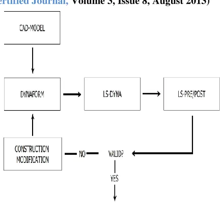
III. METHODOLOGY
Incremental forming processes can be simulated by a series of steps as presented below;
Building CAD models (support, tool blank, , part with desired shape);
Generating tool-paths for controlling the tool movement;
Building finite element model, applying boundary conditions, defining material properties, contact parameters etc;
Solving model, post processing
The procedure of running simulation in LS-DYNA is presented in figure 2.
Figure 2. Simulation procedure
IV. TOOL PATH DESIGN
[image:2.612.58.251.279.427.2]International Journal of Emerging Technology and Advanced Engineering
Website: www.ijetae.com (ISSN 2250-2459,ISO 9001:2008 Certified Journal, Volume 3, Issue 8, August 2013)
761
In the present study the punch progressively deforms the blank with a spiral movement from the top going towards the maximum depth and the path followed by the tool is generated by CATIA software and these line data’s are converted into points to input LS-DYNA software for simulation. The locus of tool path is generated by a simple program in excel and coded in dot net, the x and y co-ordinates are found out from the equation. Here ‘r’ is the radius of the circle; ‘Ɵ’ is the angle measured from the reference axis and the ‘Center distance’ is the distance from the point to the center.x= r cos Ɵ + center distance ………. (3.1)
y= r Sin Ɵ + center distance……..………... (3.2)
V. FINITE ELEMENT ANALYSYS
[image:3.612.337.558.483.668.2]For the present study, the LS-DYNA, the commercial software for FEA is used for simulation studies as this software has got combined explicit/implicit solver. Here generate different layers and each one consists of 1mm and 2mm step sizes to reach the final depth. The program was originally designed for highly transient dynamics FEA, using explicit time integration. Since LS-DYNA will treat the tools as rigid, only the tool surfaces that are in contact with the blank are required for the simulations [7]. The CAD-model for the tools will then be imported into the pre-processor Dyna Form, where the mesh is generated and the simulation process is set up. The simulation can then be run in LS-DYNA where output-files are generated. Table 1 presents input parameters used in the present numerical research. These files can then be evaluated in LS-PrePost to evaluate strains, displacements and reaction forces.
Table 1 Input parameters in SPIF
Control termination 0.102s
Blank holding force 20000N
Blank thickness 1.5mm
wall angle 35º
Tool diameters 6mm, 10mm
depth of penetration 35mm
die diameter 20mm
Step size 1mm
Young’s modulus 210 Gpa
Poisson’s ratio 0.33
Strain hardening index 0.8
Strain hardening parameter 0.21
Density of blank 7.18kg/m3
A systematic procedure is developed for the FEM simulation of single point incremental sheet metal forming process. After running the simulation, using the software d3plot-files generated that can be further analyzed. The theoretical procedures behind the finite element method and also outlines the theory behind certain modelling features in LS-DYNA such as wrinkling, thickness reduction and how they are implemented into the finite element model. Hill yeild criterion (Hill.R.1993 journal of mechanical sciences vol.35), the theory used for yield criterion is the Hill-yeild criterion and is employed in characterizing the isotropic material behaviour. This model can be employed in the stretch forming of some Aluminium alloys and steel alloys.
VI. RESULTS AND DESCUSSION
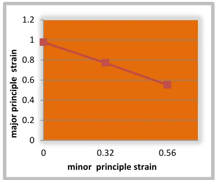
The Finite Element analysis has been carried out and the outputs are taken from the post process of LS-DYNA in order to study the thickness, depth, FLD etc. A failure range is employed to improve the accuracy of fracture prediction in the FE model, and statistical analysis is employed to examine the effects of variance in material properties on the prediction of fracture. Generally in sheet metal forming simulations, evaluation of the forming process by detecting cracks and wrinkles that would lead to failure. In this paper two cases have been studied in the present work. The Figure 3 shows failure limit curve for the SPIF in the case of tool diameter of 10 mm and with the depth of stretch with step size of 2mm.
Figure 3.Variation of major strain against minor strain in SPIF
From the figure 3, the major principle strain decreases as increasing minor principle strain.
0 0.2 0.4 0.6 0.8 1 1.2
0 0.32 0.56
m
aj
or
p
ri
n
cipl
e
str
ai
n
[image:3.612.59.278.530.709.2]International Journal of Emerging Technology and Advanced Engineering
Website: www.ijetae.com (ISSN 2250-2459,ISO 9001:2008 Certified Journal, Volume 3, Issue 8, August 2013)
762
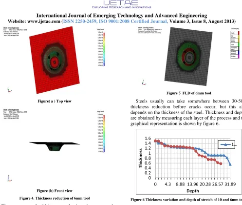
Figure( a ) Top view
Figure (b) Front view
Figure 4. Thickness reduction of 6mm tool
The amount of thickness reduction is presented graphically with different colours (fig 4). The fringe colour pattern shows the thickness reduction and here the thickness is reduced into 0.617mm from 1.5mm and there 42 layers have run and reached the depth of 31.74mm.
In the case of depth of stretch with step size of 1mm of tool diameter 6mm, failure starts at the 28th layer and observe the FLD, wrinkling tendency and wrinkles are visualized graphically with blue and purple coloures respectively as shown in figure 5.
Figure 5 FLD of 6mm tool
[image:4.612.56.553.80.500.2]Steels usually can take somewhere between 30-50% thickness reduction before cracks occur, but this also depends on the thickness of the steel. Thickness and depths are obtained by measuring each layer of the process and the graphical representation is shown by figure 6.
Figure 6 Thickness variation and depth of stretch of 10 and 6mm tools
[image:4.612.329.554.341.479.2]The graph shows that the thickness variations of 10mm and 6mm tools from 1.5 mm to 0.55 mm respectively for a depth of stretch of 31.89 mm.
Figure 7 Variation of plastic strain and depth of stretch 0
0.2 0.4 0.6 0.81 1.2 1.4 1.6
0 4.3 8.88 13.96 20.28 26.57 31.89
Th
ic
kn
e
ss
Depth
1…
0 0.5 1 1.5 2
0 10 20 30 40
p
lasti
c
str
ai
n
[image:4.612.341.549.541.687.2]International Journal of Emerging Technology and Advanced Engineering
Website: www.ijetae.com (ISSN 2250-2459,ISO 9001:2008 Certified Journal, Volume 3, Issue 8, August 2013)
763
Figure 7 shows the plastic strain against depth in single point incremental metal forming process and the plastic strain increases with increasing depth as expected. These limits depend on the deformation mode and the ratio of the surface strains.FEM simulation of SPIF process used an explicit integrate scheme for the prediction of mechanical damage in SPIF process is performed on cone shaped model. Spring back is a difficult phenomenon due to non-linearity and also that a small angular spring back could result in large deformations of the whole part and have the simulation results depends simulation software especially when deals with complicated geometries where several trial and errors might come in.
VII. CONCLUSION
In the present simulation study, the thickness reduction and failure limit curves of Incremental sheet metal forming is discussed and also the thinning and failure limit diagrams are discussed. This work investigates the capabilities of single point incremental sheet forming to provide sheet metal products with accuracy. It also demonstrates the accuracy and the reliability of 3D finite elements simulation of the process, carefully accounting the tool path strategy. Springback is a difficult phenomenon due to non-linearity and also that a small angular springback could result in large deformations of the whole part and have the simulation results depends simulation software especially when deals with complicated geometries. Where several trial and errors might come in and the total time required for run this process was 127 hours and also needed a lot of additional time. From the present study it is concluded that:
The SPIF process is a time consuming process
A greater deformation of sheet metal is possible in SPIF Small tool size is preferred to get the required shape at a faster rate, but the possibilities of failure due to localized stress are bigger.
REFERENCES
[1] S. Dejardina, S. Thibaudb, J.C. Gelina, G. Michela, Experimental investigations and numerical analysis for improving knowledge of incremental sheet forming process for sheet metal parts. Journal of Materials Processing Technology 210 (2010) 363–369
[2] Salah B M.Echrif AND MeftahHrairi, Process simulation and quality Evaluation of incremental sheet metal formingIIUM Engineering Journal, Special Issue, Mechanical Engineering, 2011.
[3] A. Attanasioa, E. Cerettia, C. Giardinib, L. Mazzonia,Asymmetric two points incremental forming: Improving surface quality and geometric accuracy by tool path optimization, journal of materials processing technology 1 9 7 ( 2 0 0 8 ) 59–67
[4] M. Ham and J. Jeswiet (1), Forming Limit Curves in Single Point Incremental Forming, Mechanical and Materials Engineering, Queen’s University, Kingston, ON, Canada.
[5] Jong-Jin Park*, Yung-Ho Kim, Fundamental studies on the incremental sheet metal forming technique, Journal of Materials Processing Technology 140 (2003) 447–453.
[6] W.C. Emmensa,*, G. Sebastianib, A.H. van den Boogaardc, The technology of Incremental Sheet Forming—A brief review of the history, Journal of Materials Processing Technology 210 (2010) 981–997.
[7] F. Capece Minutolo, M. Durante, A. Formisano, A. Langella, Evaluation of the maximum slope angle of simple geometries carried out by incremental forming process. Journal of Materials Processing Technology 194 (2007) 145–150.
[8] Minoru Yamashita*, Manabu Gotoh, Shin-YaAtsumi, Numerical simulation of incremental forming of sheet metal, journal of materials processing technology 1 9 9 (2 0 0 8 ) 163–172.
[9] M. Durante*, A. Formisano, A. Langella, Comparison between analytical and experimental roughness values of components created by incremental forming. Journal of Materials Processing Technology 210 (2010) 1934-19
[10] Halliquist, J.-O., 1989. DYNA3D User’s Manual.