LabVIEW
User Manual
Worldwide Technical Support and Product Information ni.com
National Instruments Corporate Headquarters
11500 North Mopac Expressway Austin, Texas 78759-3504 USA Tel: 512 683 0100
Worldwide Offices
Australia 61 2 9672 8846, Austria 43 0 662 45 79 90 0, Belgium 32 0 2 757 00 20, Brazil 55 11 3262 3599, Canada (Calgary) 403 274 9391, Canada (Montreal) 514 288 5722, Canada (Ottawa) 613 233 5949, Canada (Québec) 514 694 8521, Canada (Toronto) 905 785 0085, Canada (Vancouver) 514 685 7530, China 86 21 6555 7838, Czech Republic 420 2 2423 5774, Denmark 45 45 76 26 00,
Finland 385 0 9 725 725 11, France 33 0 1 48 14 24 24, Germany 49 0 89 741 31 30, Greece 30 2 10 42 96 427, Hong Kong 2645 3186, India 91 80 51190000, Israel 972 0 3 6393737, Italy 39 02 413091,
Japan 81 3 5472 2970, Korea 82 02 3451 3400, Malaysia 603 9059 6711, Mexico 001 800 010 0793, Netherlands 31 0 348 433 466, New Zealand 64 09 914 0488, Norway 47 0 32 27 73 00,
Poland 48 0 22 3390 150, Portugal 351 210 311 210, Russia 7 095 238 7139, Singapore 65 6 226 5886, Slovenia 386 3 425 4200, South Africa 27 0 11 805 8197, Spain 34 91 640 0085, Sweden 46 0 8 587 895 00, Switzerland 41 56 200 51 51, Taiwan 886 2 2528 7227, United Kingdom 44 0 1635 523545
Important Information
Warranty
The media on which you receive National Instruments software are warranted not to fail to execute programming instructions, due to defects in materials and workmanship, for a period of 90 days from date of shipment, as evidenced by receipts or other documentation. National Instruments will, at its option, repair or replace software media that do not execute programming instructions if National Instruments receives notice of such defects during the warranty period. National Instruments does not warrant that the operation of the software shall be uninterrupted or error free.
A Return Material Authorization (RMA) number must be obtained from the factory and clearly marked on the outside of the package before any equipment will be accepted for warranty work. National Instruments will pay the shipping costs of returning to the owner parts which are covered by warranty.
National Instruments believes that the information in this document is accurate. The document has been carefully reviewed for technical accuracy. In the event that technical or typographical errors exist, National Instruments reserves the right to make changes to subsequent editions of this document without prior notice to holders of this edition. The reader should consult National Instruments if errors are suspected. In no event shall National Instruments be liable for any damages arising out of or related to this document or the information contained in it. EXCEPTASSPECIFIEDHEREIN, NATIONAL INSTRUMENTSMAKESNOWARRANTIES, EXPRESSORIMPLIED, ANDSPECIFICALLYDISCLAIMSANYWARRANTYOF MERCHANTABILITYORFITNESSFORAPARTICULARPURPOSE. CUSTOMER’SRIGHTTORECOVERDAMAGESCAUSEDBYFAULTORNEGLIGENCEONTHEPARTOF
NATIONAL INSTRUMENTSSHALLBELIMITEDTOTHEAMOUNTTHERETOFOREPAIDBYTHECUSTOMER. NATIONAL INSTRUMENTSWILLNOTBELIABLEFOR DAMAGESRESULTINGFROMLOSSOFDATA, PROFITS, USEOFPRODUCTS, ORINCIDENTALORCONSEQUENTIALDAMAGES, EVENIFADVISEDOFTHEPOSSIBILITY THEREOF. This limitation of the liability of National Instruments will apply regardless of the form of action, whether in contract or tort, including negligence. Any action against National Instruments must be brought within one year after the cause of action accrues. National Instruments shall not be liable for any delay in performance due to causes beyond its reasonable control. The warranty provided herein does not cover damages, defects, malfunctions, or service failures caused by owner’s failure to follow the National Instruments installation, operation, or maintenance instructions; owner’s modification of the product; owner’s abuse, misuse, or negligent acts; and power failure or surges, fire, flood, accident, actions of third parties, or other events outside reasonable control.
Copyright
Under the copyright laws, this publication may not be reproduced or transmitted in any form, electronic or mechanical, including photocopying, recording, storing in an information retrieval system, or translating, in whole or in part, without the prior written consent of National Instruments Corporation.
Trademarks
CVI™, DAQPad™, DataSocket™, DIAdem™, IMAQ™, IVI™, LabVIEW™, Measurement Studio™, National Instruments™, NI™, ni.com™,
NI-DAQ™, NI Developer Zone™, NI-IMAQ™, NI-VISA™, NI-VXI™, and SCXI™ are trademarks of National Instruments Corporation.
Product and company names mentioned herein are trademarks or trade names of their respective companies.
Patents
For patents covering National Instruments products, refer to the appropriate location: Help»Patents in your software, the patents.txt file on your CD, or ni.com/patents.
WARNING REGARDING USE OF NATIONAL INSTRUMENTS PRODUCTS
(1) NATIONAL INSTRUMENTS PRODUCTS ARE NOT DESIGNED WITH COMPONENTS AND TESTING FOR A LEVEL OF RELIABILITY SUITABLE FOR USE IN OR IN CONNECTION WITH SURGICAL IMPLANTS OR AS CRITICAL COMPONENTS IN ANY LIFE SUPPORT SYSTEMS WHOSE FAILURE TO PERFORM CAN REASONABLY BE EXPECTED TO CAUSE SIGNIFICANT INJURY TO A HUMAN.
(2) IN ANY APPLICATION, INCLUDING THE ABOVE, RELIABILITY OF OPERATION OF THE SOFTWARE PRODUCTS CAN BE IMPAIRED BY ADVERSE FACTORS, INCLUDING BUT NOT LIMITED TO FLUCTUATIONS IN ELECTRICAL POWER SUPPLY, COMPUTER HARDWARE MALFUNCTIONS, COMPUTER OPERATING SYSTEM SOFTWARE FITNESS, FITNESS OF COMPILERS AND DEVELOPMENT SOFTWARE USED TO DEVELOP AN APPLICATION, INSTALLATION ERRORS, SOFTWARE AND HARDWARE COMPATIBILITY PROBLEMS, MALFUNCTIONS OR FAILURES OF ELECTRONIC MONITORING OR CONTROL DEVICES, TRANSIENT FAILURES OF ELECTRONIC SYSTEMS (HARDWARE AND/OR SOFTWARE), UNANTICIPATED USES OR MISUSES, OR ERRORS ON THE PART OF THE USER OR APPLICATIONS DESIGNER (ADVERSE FACTORS SUCH AS THESE ARE HEREAFTER COLLECTIVELY TERMED “SYSTEM FAILURES”). ANY APPLICATION WHERE A SYSTEM FAILURE WOULD CREATE A RISK OF HARM TO PROPERTY OR PERSONS (INCLUDING THE RISK OF BODILY INJURY AND DEATH) SHOULD NOT BE RELIANT SOLELY UPON ONE FORM OF ELECTRONIC SYSTEM DUE TO THE RISK OF SYSTEM FAILURE. TO AVOID DAMAGE, INJURY, OR DEATH, THE USER OR APPLICATION DESIGNER MUST TAKE REASONABLY PRUDENT STEPS TO PROTECT AGAINST SYSTEM FAILURES, INCLUDING BUT NOT LIMITED TO BACK-UP OR SHUT DOWN MECHANISMS. BECAUSE EACH END-USER SYSTEM IS CUSTOMIZED AND DIFFERS FROM NATIONAL INSTRUMENTS' TESTING PLATFORMS AND BECAUSE A USER OR APPLICATION DESIGNER MAY USE NATIONAL INSTRUMENTS PRODUCTS IN COMBINATION WITH OTHER PRODUCTS IN A MANNER NOT EVALUATED OR CONTEMPLATED BY NATIONAL
Contents
About This Manual
Organization of This Manual ...xxi Conventions ...xxii
P
ARTI
LabVIEW Concepts
Chapter 1
Introduction to LabVIEW
LabVIEW Documentation Resources...1-1 LabVIEW Template VIs, Example VIs, and Tools ...1-4 LabVIEW Template VIs...1-4 LabVIEW Example VIs ...1-4 LabVIEW Tools ...1-4
Chapter 2
Introduction to Virtual Instruments
Front Panel ...2-1 Block Diagram ...2-2 Terminals...2-3 Nodes...2-4 Wires...2-4 Structures...2-4 Icon and Connector Pane ...2-4 Using and Customizing VIs and SubVIs ...2-5
Chapter 3
LabVIEW Environment
Toolbar ... 3-4 Context Help Window... 3-4 Customizing Your Work Environment ... 3-5 Customizing the Controls and Functions Palettes... 3-6
Adding VIs and Controls to the User and Instrument Drivers
Subpalettes ... 3-6 Creating and Editing Custom Palette View ... 3-6 How LabVIEW Stores Views ... 3-7 Building ActiveX Subpalettes ... 3-7 Representing Toolsets and Modules in the Palettes ... 3-8 Setting Work Environment Options... 3-8 How LabVIEW Stores Options ... 3-8 Windows... 3-8 Mac OS... 3-8 UNIX... 3-9
Chapter 4
Building the Front Panel
Configuring Front Panel Objects... 4-1 Showing and Hiding Optional Elements... 4-2 Changing Controls to Indicators and Indicators to Controls... 4-2 Replacing Front Panel Objects... 4-2 Configuring the Front Panel ... 4-3 Setting Keyboard Shortcuts for Controls ... 4-3 Controlling Button Behavior with Key Navigation... 4-4 Setting the Tabbing Order of Front Panel Objects ... 4-4 Coloring Objects ... 4-5 Using Imported Graphics ... 4-5 Aligning and Distributing Objects ... 4-6 Grouping and Locking Objects ... 4-6 Resizing Objects ... 4-6 Scaling Front Panel Objects ... 4-7 Adding Space to the Front Panel without Resizing the Window... 4-9 Front Panel Controls and Indicators ... 4-9 3D and Classic Controls and Indicators ... 4-9 Slides, Knobs, Dials, Digital Displays, and Time Stamps ... 4-10
Chapter 5
Building the Block Diagram
Block Diagram Data Flow ...5-25 Data Dependency and Artificial Data Dependency...5-26 Missing Data Dependencies...5-27 Data Flow and Managing Memory...5-27 Designing the Block Diagram...5-28
Chapter 6
Running and Debugging VIs
Chapter 7
Creating VIs and SubVIs
Planning and Designing Your Project ... 7-1 Designing Projects with Multiple Developers ... 7-2 VI Templates ... 7-2 Creating VI Templates ... 7-3 Other Document Types ... 7-3 Using Built-In VIs and Functions... 7-3 Building Instrument Control and Data Acquisition VIs and Functions... 7-3 Building VIs That Access Other VIs ... 7-4 Building VIs That Communicate with Other Applications ... 7-4 SubVIs ... 7-4 Watching for Common Operations ... 7-5 Setting up the Connector Pane ... 7-6
Setting Required, Recommended, and Optional Inputs
and Outputs ... 7-8 Creating an Icon ... 7-8 Displaying SubVIs and Express VIs as Icons or Expandable Nodes ... 7-9 Creating SubVIs from Sections of a VI ... 7-10 Designing SubVIs ... 7-10 Viewing the Hierarchy of VIs ... 7-11 Saving VIs ... 7-12 Advantages of Saving VIs as Individual Files ... 7-12 Advantages of Saving VIs as Libraries... 7-12 Managing VIs in Libraries ... 7-13 Naming VIs ... 7-13 Saving for a Previous Version ... 7-14 Distributing VIs ... 7-14 Building Stand-Alone Applications and Shared Libraries ... 7-15
P
ARTII
Building and Editing VIs
Chapter 8
Loops and Structures
Auto-Indexing Loops...8-4 Auto-Indexing to Set the For Loop Count ...8-4 Auto-Indexing with While Loops ...8-5 Using Loops to Build Arrays...8-5 Shift Registers and the Feedback Node in Loops...8-6 Shift Registers ...8-6 Stacked Shift Registers ...8-7 Replacing Shift Registers with Tunnels...8-7 Replacing Tunnels with Shift Registers...8-8 Feedback Node ...8-8 Initializing Feedback Nodes...8-10 Replacing Shift Registers with a Feedback Node ...8-10 Controlling Timing...8-10 Case and Sequence Structures ...8-11 Case Structures ...8-11 Case Selector Values and Data Types...8-11 Input and Output Tunnels ...8-12 Using Case Structures for Error Handling ...8-13 Sequence Structures...8-13 Flat Sequence Structure ...8-13 Stacked Sequence Structure ...8-13 Using Sequence Structures...8-14 Avoiding Overusing Sequence Structures ...8-15 Replacing Sequence Structures ...8-16
Chapter 9
Event-Driven Programming
Chapter 10
Grouping Data Using Strings, Arrays, and Clusters
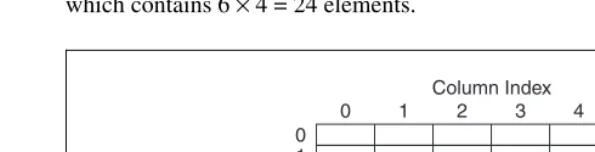
Strings... 10-1 Strings on the Front Panel ... 10-2 String Display Types ... 10-2 Tables ... 10-2 Programmatically Editing Strings ... 10-3 Formatting Strings... 10-4 Format Specifiers... 10-4 Numerics and Strings ... 10-5 Converting Data to and from XML... 10-5 Using XML-Based Data Types ... 10-7 LabVIEW XML Schema ... 10-8 Grouping Data with Arrays and Clusters ... 10-8 Arrays... 10-8 Indexes... 10-8 Examples of Arrays ... 10-9 Restrictions for Arrays... 10-11 Creating Array Controls, Indicators, and Constants... 10-11 Array Index Display ... 10-12 Array Functions ... 10-13 Automatically Resizing Array Functions ... 10-13 Clusters... 10-14
Chapter 11
Local and Global Variables
Chapter 12
Graphs and Charts
Types of Graphs and Charts...12-1 Graph and Chart Options ...12-2 Multiple X- and Y-Scales on Graphs and Charts ...12-2 Anti-Aliased Line Plots for Graphs and Charts...12-2 Customizing Graph and Chart Appearance ...12-3 Customizing Graphs ...12-3 Graph Cursors ...12-4 Autoscaling ...12-5 Waveform Graph Scale Legend ...12-5 Axis Formatting ...12-5 Dynamically Formatting Graphs...12-6 Using Smooth Updates...12-6 Customizing Charts ...12-6 Chart History Length ...12-7 Chart Update Modes ...12-7 Overlaid versus Stacked Plots...12-7 Waveform and XY Graphs ...12-8 Single-Plot Waveform Graph Data Types...12-9 Multiplot Waveform Graph...12-9 Single-Plot XY Graph Data Types ...12-10 Multiplot XY Graph Data Types...12-11 Waveform Charts ...12-11 Intensity Graphs and Charts...12-12 Color Mapping...12-13 Intensity Chart Options...12-14 Intensity Graph Options ...12-14 Digital Waveform Graphs...12-14 Masking Data...12-17 3D Graphs ...12-17 Waveform Data Type...12-18 Digital Waveform Data Type ...12-18
Chapter 13
Graphics and Sound VIs
Picture Functions VIs ... 13-4 Creating and Modifying Colors with the Picture Functions VIs ... 13-6 Graphics Formats VIs... 13-6 Sound VIs ... 13-7
Chapter 14
File I/O
Chapter 15
Documenting and Printing VIs
Documenting VIs ...15-1 Setting up the VI Revision History ...15-1 Revision Numbers...15-2 Creating VI and Object Descriptions ...15-2 Printing Documentation...15-3 Saving Documentation to HTML, RTF, or Text Files...15-3 Selecting Graphic Formats for HTML Files...15-4 Naming Conventions for Graphic Files...15-4 Creating Your Own Help Files ...15-4 Printing VIs...15-5 Printing the Active Window...15-5 Printing VIs Programmatically...15-6 Printing the Front Panel of a VI after the VI Runs ...15-6 Using a SubVI to Print Data from a Higher Level VI ...15-6 Generating and Printing Reports...15-7 Additional Printing Techniques...15-7
Chapter 16
Customizing VIs
Configuring the Appearance and Behavior of VIs ...16-1 Customizing Menus ...16-2 Creating Menus ...16-2 Menu Selection Handling ...16-3
Chapter 17
Programmatically Controlling VIs
Dynamically Loading and Calling VIs... 17-7 Call By Reference Nodes and Strictly Typed VI Refnums ... 17-7 Editing and Running VIs on Remote Computers ... 17-8 Controlling Front Panel Objects ... 17-8 Strictly Typed and Weakly Typed Control Refnums... 17-9
Chapter 18
Networking in LabVIEW
Choosing among File I/O, VI Server, ActiveX, and Networking ... 18-1 LabVIEW as a Network Client and Server ... 18-2 Using DataSocket Technology ... 18-2 Specifying a URL... 18-3 Data Formats Supported by DataSocket ... 18-4 Using DataSocket on the Front Panel ... 18-5 Reading and Writing Live Data through the Block Diagram ... 18-6
Programmatically Opening and Closing DataSocket
Connections ... 18-7 Buffering DataSocket Data... 18-7 Reporting Diagnostics ... 18-8 DataSocket and Variant Data... 18-9 Publishing VIs on the Web... 18-10
Web Server Options ... 18-10 Creating HTML Documents ... 18-11 Publishing Front Panel Images ... 18-11 Front Panel Image Formats... 18-11 Viewing and Controlling Front Panels Remotely ... 18-12 Configuring the Server for Clients... 18-12 Remote Panel License ... 18-12 Viewing and Controlling Front Panels in LabVIEW or from
a Web Browser ... 18-13 Viewing and Controlling Front Panels in LabVIEW ... 18-13 Viewing and Controlling Front Panels from a Web Browser ... 18-14 Functionality Not Supported in Viewing and Controlling Remote
Low-Level Communications Applications ...18-19 TCP and UDP ...18-19 Apple Events and PPC Toolbox (Mac OS) ...18-20 Pipe VIs (UNIX)...18-20 Executing System-Level Commands (Windows and UNIX)...18-20
Chapter 19
Windows Connectivity
.NET Environment...19-2 .NET Functions and Nodes ...19-3 LabVIEW as a .NET Client ...19-4 Data Type Mapping ...19-5 Deploying .NET Applications ...19-5 Deploying an Executable...19-5 Deploying VIs ...19-6 Deploying DLLs...19-6 Configuring a .NET Client Application (Advanced)...19-6 ActiveX Objects, Properties, Methods, and Events...19-6 ActiveX VIs, Functions, Controls, and Indicators ...19-7 LabVIEW as an ActiveX Client ...19-7 Accessing an ActiveX-Enabled Application ...19-8 Inserting an ActiveX Object on the Front Panel ...19-8 Design Mode for ActiveX Objects...19-9 Setting ActiveX Properties ...19-9 ActiveX Property Browser...19-9 ActiveX Property Pages ...19-9 Property Nodes...19-10 LabVIEW as an ActiveX Server...19-11 Support for Custom ActiveX Automation Interfaces ...19-11 Using Constants to Set Parameters in ActiveX VIs...19-11 ActiveX Events ...19-12 Handling ActiveX Events...19-13
Chapter 20
Calling Code from Text-Based Programming Languages
Chapter 21
Formulas and Equations
Methods for Using Equations in LabVIEW ... 21-1 Formula Nodes ... 21-1 Using the Formula Node ... 21-2 Variables in the Formula Node ... 21-3 Expression Nodes ... 21-3 Polymorphism in Expression Nodes ... 21-4 MATLAB Script Nodes ... 21-4 Programming Suggestions for MATLAB Scripts... 21-5
Appendix A
Organization of LabVIEW
Organization of the LabVIEW Directory Structure ... A-1 Libraries ... A-1 Structure and Support... A-2 Learning and Instruction ... A-2 Documentation ... A-2 Mac OS ... A-2 Suggested Location for Saving Files ... A-2
Appendix B
Polymorphic Functions
Numeric Conversion... B-1 Polymorphism for Numeric Functions ... B-2 Polymorphism for Boolean Functions... B-4 Polymorphism for Array Functions... B-5 Polymorphism for String Functions ... B-5 Polymorphism for String Conversion Functions ... B-5 Polymorphism for Additional String to Number Functions... B-5 Polymorphism for Cluster Functions... B-6 Polymorphism for Comparison Functions... B-6 Polymorphism for Log Functions... B-7
Appendix C
Comparison Functions
Comparing Arrays and Clusters...C-2 Arrays ...C-2 Compare Elements Mode...C-2 Compare Aggregates Mode ...C-3 Clusters ...C-3 Compare Elements Mode...C-3 Compare Aggregates Mode ...C-3
Appendix D
Technical Support and Professional Services
Glossary
About This Manual
This manual describes the LabVIEW graphical programming environment and techniques for building applications in LabVIEW, such as test and measurement, data acquisition, instrument control, datalogging, measurement analysis, and report generation applications.
Use this manual to learn about LabVIEW programming features, including the LabVIEW user interface and programming workspaces, and the LabVIEW palettes and tools. This manual does not include specific information about each palette, tool, menu, dialog box, control, or built-in VI or function. Refer to the LabVIEW Help for more information about these items and for detailed, step-by-step instructions for using LabVIEW features and for building specific applications. Refer to the LabVIEW Documentation Resources section of Chapter 1, Introduction to LabVIEW, for more information about the LabVIEW Help and accessing it.
The LabVIEW User Manual is also available in Portable Document Format (PDF). If you select the Complete install option, LabVIEW installs PDF versions of all LabVIEW manuals, which you can access by selecting Help»Search the LabVIEW Bookshelf in LabVIEW.
Note You must have Adobe Acrobat Reader with Search and Accessibility 5.0.5 or later installed to view the PDFs. Refer to the Adobe Systems Incorporated Web site at www.adobe.com to download Acrobat Reader.
You can access the PDFs from the LabVIEW Help, but you must install the PDFs to do so. Refer to the LabVIEW Documentation Resources section of Chapter 1, Introduction to LabVIEW, for information about accessing the PDFs in the LabVIEW Bookshelf.
Organization of This Manual
The LabVIEW User Manual includes two sections. Part I, LabVIEW Concepts, describes programming concepts for building applications in LabVIEW. The chapters in this section introduce you to the LabVIEW programming environment and help you plan your application.
Conventions
The following conventions appear in this manual:
» The » symbol leads you through nested menu items and dialog box options to a final action. The sequence File»Page Setup»Options directs you to pull down the File menu, select the Page Setup item, and select Options from the last dialog box.
This icon denotes a tip, which alerts you to advisory information.
This icon denotes a note, which alerts you to important information.
This icon denotes a caution, which advises you of precautions to take to avoid injury, data loss, or a system crash.
bold Bold text denotes items that you must select or click in the software, such as menu items and dialog box options. Bold text also denotes parameter names, controls and buttons on the front panel, dialog boxes, sections of dialog boxes, menu names, and palette names.
italic Italic text denotes variables, emphasis, a cross reference, or an introduction to a key concept. This font also denotes text that is a placeholder for a word or value that you must supply.
monospace Text in this font denotes text or characters that you should enter from the keyboard, sections of code, programming examples, and syntax examples. This font is also used for the proper names of disk drives, paths, directories, programs, subprograms, subroutines, device names, functions, operations, variables, filenames and extensions, and code excerpts.
monospace bold Bold text in this font denotes the messages and responses that the computer automatically prints to the screen. This font also emphasizes lines of code that are different from the other examples.
monospace italic Italic text in this font denotes text that is a placeholder for a word or value that you must supply.
Platform Text in this font denotes a specific platform and indicates that the text following it applies only to that platform.
Part I
LabVIEW Concepts
This part describes programming concepts for building applications in LabVIEW. The chapters in this section introduce you to the LabVIEW programming environment and help you plan your application.
Part I, LabVIEW Concepts, contains the following chapters:
• Chapter 1, Introduction to LabVIEW, describes LabVIEW, its extensive documentation, and tools to help you design and build VIs.
• Chapter 2, Introduction to Virtual Instruments, describes the components of virtual instruments, or VIs.
• Chapter 3, LabVIEW Environment, describes the LabVIEW palettes, tools, and menus you use to build the front panels and block diagrams of VIs. This chapter also describes how to customize the LabVIEW palettes and set several work environment options.
• Chapter 4, Building the Front Panel, describes how to build the front panel of a VI.
• Chapter 5, Building the Block Diagram, describes how to build the block diagram of a VI.
• Chapter 6, Running and Debugging VIs, describes how to configure how a VI runs and to identify problems with block diagram organization or with the data passing through the block diagram.
1
Introduction to LabVIEW
LabVIEW is a graphical programming language that uses icons instead of lines of text to create applications. In contrast to text-based programming languages, where instructions determine program execution, LabVIEW uses dataflow programming, where the flow of data determines execution.
In LabVIEW, you build a user interface with a set of tools and objects. The user interface is known as the front panel. You then add code using graphical representations of functions to control the front panel objects. The block diagram contains this code. In some ways, the block diagram resembles a flowchart.
You can purchase several add-on software toolsets for developing specialized applications. All the toolsets integrate seamlessly in LabVIEW. Refer to the National Instruments Web site at ni.com for more information about these toolsets.
LabVIEW Documentation Resources
LabVIEW includes extensive documentation for new and experienced LabVIEW users. All LabVIEW manuals and Application Notes are also available as PDFs. You must have Adobe Acrobat Reader with Search and Accessibility 5.0.5 or later installed to view the PDFs. Refer to the Adobe Systems Incorporated Web site at www.adobe.com to download Acrobat Reader. Refer to the National Instruments Product Manuals Library at ni.com/manuals for updated documentation resources.
• LabVIEW Bookshelf—Use this PDF to search PDF versions of all the LabVIEW manuals and Application Notes. Access the LabVIEW Bookshelf by selecting Help»Search the LabVIEW Bookshelf.
• Getting Started with LabVIEW—Use this manual to familiarize yourself with the LabVIEW graphical programming environment and the basic LabVIEW features you use to build data acquisition and instrument control applications.
• LabVIEW User Manual—Use this manual to learn about LabVIEW programming concepts, techniques, features, VIs, and functions you can use to create test and measurement, data acquisition, instrument control, datalogging, measurement analysis, and report generation applications.
• LabVIEW Help—Use this help file as a reference for information about LabVIEW palettes, menus, tools, VIs, and functions. The LabVIEW Help also includes step-by-step instructions for using LabVIEW features. Access the LabVIEW Help by selecting Help» VI, Function, and How-To Help.
The LabVIEW Help includes links to the following resources:
– LabVIEW Bookshelf, which includes PDF versions of all the LabVIEW manuals and Application Notes
– Technical support resources on the National Instruments Web site, such as the NI Developer Zone, the KnowledgeBase, and the Product Manuals Library
Note (Mac OS and UNIX) National Instruments recommends that you use Netscape 6.0 or later or Internet Explorer 5.0 or later to view the LabVIEW Help.
• LabVIEW Measurements Manual—Use this manual to learn more about building data acquisition and instrument control applications in LabVIEW. If you are a new LabVIEW user, read the Getting Started with LabVIEW manual and the LabVIEW User Manual before you read this manual.
• LabVIEW Application Builder User Guide—Use this document to learn about the LabVIEW Application Builder, which is included in the LabVIEW Professional Development System and is available for purchase separately. This user guide contains instructions for installing the Application Builder, describes system requirements for
applications, and describes the changes introduced between previous versions and the current version. This user guide also describes caveats and recommendations to consider when you build a VI into an application or shared library.
Note The printed LabVIEW Development Guidelines manual is available only in the LabVIEW Professional Development System. The PDF is available in all packages of LabVIEW.
• LabVIEW Analysis Concepts—Use this manual to learn about the analysis concepts used by LabVIEW. This manual includes information about signal generation, the fast Fourier transform (FFT) and the discrete Fourier transform (DFT), smoothing windows, curve fitting, linear algebra, fundamental concepts of probability and statistics, and point-by-point analysis for real-time analysis.
Note The LabVIEW Analysis Concepts manual is available only as a PDF.
• Using External Code in LabVIEW—Use thismanual to learn how to use Code Interface Nodes and external subroutines to import code written in text-based programming languages. The manual includes information about calling DLLs, shared external subroutines, libraries of functions, memory and file manipulation routines, and diagnostic routines.
Note The Using External Code in LabVIEW manual is available only as a PDF.
• LabVIEW Release Notes—Use these release notes to install and uninstall LabVIEW. The release notes also describe the system requirements for the LabVIEW software and known issues with LabVIEW.
• LabVIEW Upgrade Notes—Use these upgrade notes to upgrade LabVIEW for Windows, Mac OS, and UNIX to the latest version. The upgrade notes also describe new features and issues you might encounter when you upgrade.
• LabVIEW Application Notes—Use the LabVIEW Application Notes to learn about advanced or specialized LabVIEW concepts and applications. Refer to the NI Developer Zone at ni.com/zone for new and updated Application Notes.
LabVIEW Template VIs, Example VIs, and Tools
Use the LabVIEW template VIs, example VIs, and tools to help you design and build VIs.
LabVIEW Template VIs
The LabVIEW template VIs include the subVIs, functions, structures, and front panel objects you need to get started building common measurement applications. Template VIs open as untitled VIs that you must save. Select File»New to display the New dialog box, which includes the template VIs. You also can display the New dialog box by clicking the New button on the LabVIEW dialog box.
LabVIEW Example VIs
LabVIEW includes hundreds of example VIs you can use and incorporate into your own VIs. You can modify an example to fit your application, or you can copy and paste from one or more examples into your own VI. Browse or search the example VIs by selecting Help»Find Examples. Refer to the NI Developer Zone at ni.com/zone for additional example VIs.
LabVIEW Tools
LabVIEW includes many tools to help you quickly configure your measurement devices. You can access the following tools from the Tools menu.
• (Windows) Measurement & Automation Explorer (MAX) helps you configure National Instruments hardware and software.
• (Mac OS 9 or earlier) The NI-DAQ Configuration Utility helps you configure National Instruments DAQ hardware.
• (Mac OS 9 or earlier) The DAQ Channel Wizard helps you define what type of device is connected to the DAQ hardware channels. After you define a channel, the DAQ Channel Wizard remembers the settings.
• (Mac OS 9 or earlier) The DAQ Channel Viewer lists the configured DAQ channels.
Use the DAQ Assistant to graphically configure channels or common measurement tasks. You can access the DAQ Assistant in the following ways:
• Place the DAQ Assistant Express VI on the block diagram.
• Right-click a DAQmx Global Channel control and select New Channel (DAQ Assistant) from the shortcut menu. Right-click a DAQmx Task Name control and select New Task (DAQ Assistant) from the shortcut menu. Right-click a DAQmx Scale Name control and select New Scale (DAQ Assistant) from the shortcut menu.
• Launch Measurement & Automation Explorer and select Data Neighborhood or Scales from the Configuration tree. Click the Create New button. Configure a NI-DAQmx channel, task, or scale.
2
Introduction to Virtual
Instruments
LabVIEW programs are called virtual instruments, or VIs, because their appearance and operation imitate physical instruments, such as oscilloscopes and multimeters. Every VI uses functions that manipulate input from the user interface or other sources and display that information or move it to other files or other computers.
A VI contains the following three components:
• Front panel—Serves as the user interface.
• Block diagram—Contains the graphical source code that defines the functionality of the VI.
• Icon and connector pane—Identifies the VI so that you can use the VI in another VI. A VI within another VI is called a subVI. A subVI corresponds to a subroutine in text-based programming languages.
For more information…
Refer to the LabVIEW Help for more information about creating VIs and subVIs.
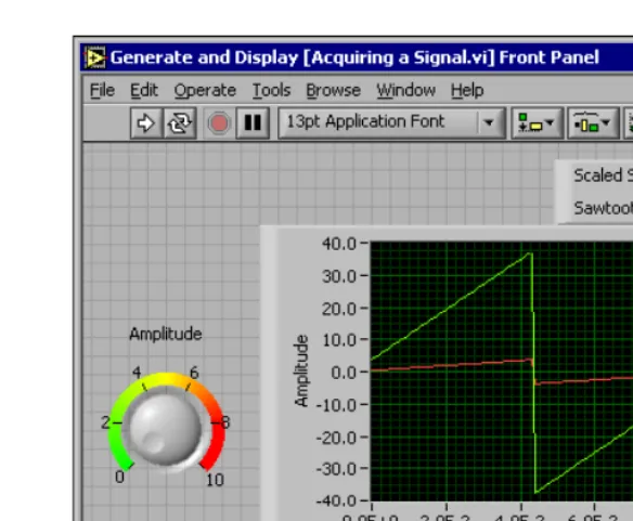
Front Panel
Figure 2-1. Example of a Front Panel
You build the front panel with controls and indicators, which are the interactive input and output terminals of the VI, respectively. Controls are knobs, push buttons, dials, and other input devices. Indicators are graphs, LEDs, and other displays. Controls simulate instrument input devices and supply data to the block diagram of the VI. Indicators simulate instrument output devices and display data the block diagram acquires or generates. Refer to Chapter 4, Building the Front Panel, for more information about the front panel.
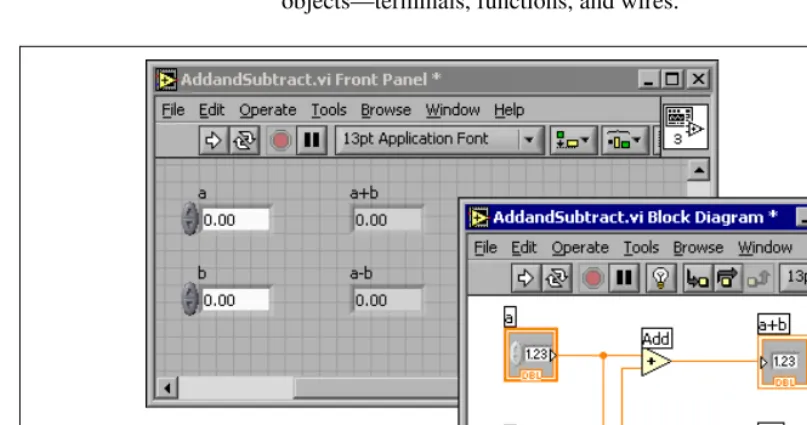
Block Diagram
After you build the front panel, you add code using graphical
The VI in Figure 2-2 shows several primary block diagram objects—terminals, functions, and wires.
Figure 2-2. Example of a Block Diagram and Corresponding Front Panel
Terminals
The terminals represent the data type of the control or indicator. You can configure front panel controls or indicators to appear as icon or data type terminals on the block diagram. By default, front panel objects appear as icon terminals. For example, a knob icon terminal shown at left, represents a knob on the front panel. The DBL at the bottom of the terminal represents a data type of double-precision, floating-point numeric. A DBL terminal, shown at left, represents a double-precision, floating-point numeric control or indicator. Refer to the Control and Indicator Data Types section of Chapter 5, Building the Block Diagram, for more information about data types in LabVIEW and their graphical representations.
Nodes
Nodes are objects on the block diagram that have inputs and/or outputs and perform operations when a VI runs. They are analogous to statements, operators, functions, and subroutines in text-based programming
languages. The Add and Subtract functions in Figure 2-2 are nodes. Refer to the Block Diagram Nodes section of Chapter 5, Building the Block Diagram, for more information about nodes.
Wires
You transfer data among block diagram objects through wires. In Figure 2-2, wires connect the control and indicator terminals to the Add and Subtract functions. Each wire has a single data source, but you can wire it to many VIs and functions that read the data. Wires are different colors, styles, and thicknesses, depending on their data types. A broken wire appears as a dashed black line with a red X in the middle. Refer to the Using Wires to Link Block Diagram Objects section of Chapter 5, Building the Block Diagram, for more information about wires.
Structures
Structures are graphical representations of the loops and case statements of text-based programming languages. Use structures on the block diagram to repeat blocks of code and to execute code conditionally or in a specific order. Refer to Chapter 8, Loops and Structures, for examples and more information about structures.
Icon and Connector Pane
After you build a VI front panel and block diagram, build the icon and the connector pane so you can use the VI as a subVI. Every VI displays an icon, such as the one shown at left, in the upper right corner of the front panel and block diagram windows. An icon is a graphical representation of a VI. It can contain text, images, or a combination of both. If you use a VI as a subVI, the icon identifies the subVI on the block diagram of the VI. You can double-click the icon to customize or edit it. Refer to the Creating an Icon section of Chapter 7, Creating VIs and SubVIs, for more information about icons.
inputs and outputs you can wire to the VI so you can use it as a subVI. A connector pane receives data at its input terminals and passes the data to the block diagram code through the front panel controls and receives the results at its output terminals from the front panel indicators.
When you view the connector pane for the first time, you see a connector pattern. You can select a different pattern if you want to. The connector pane generally has one terminal for each control or indicator on the front panel. You can assign up to 28 terminals to a connector pane. If you anticipate changes to the VI that would require a new input or output, leave extra terminals unassigned. Refer to the Setting up the Connector Pane section of Chapter 7, Creating VIs and SubVIs, for more information about setting up connector panes.
Note Try not to assign more than 16 terminals to a VI. Too many terminals can reduce the readability and usability of the VI.
Using and Customizing VIs and SubVIs
After you build a VI and create its icon and connector pane, you can use it as a subVI. Refer to the SubVIs section of Chapter 7, Creating VIs and SubVIs, for more information about subVIs.
You can save VIs as individual files, or you can group several VIs together and save them in a VI library. Refer to the Saving VIs section of Chapter 7, Creating VIs and SubVIs, for more information about saving VIs in libraries.
3
LabVIEW Environment
Use the LabVIEW palettes, tools, and menus to build the front panels and block diagrams of VIs. You can customize the Controls and Functions palettes, and you can set several work environment options.
For more information…
Refer to the LabVIEW Help for more information about using the palettes, menus, and toolbar, and customizing your work environment.
Controls Palette
The Controls palette is available only on the front panel. The Controls palette contains the controls and indicators you use to create the front panel. The controls and indicators are located on subpalettes based on the types of controls and indicators. Refer to the Front Panel Controls and Indicators section of Chapter 4, Building the Front Panel, for more information about the types of controls and indicators. The controls and indicators located on the Controls palette depend on the palette view currently selected. Refer to the Creating and Editing Custom Palette View section of this chapter for more information about palette views.
Select Window»Show Controls Palette or right-click the front panel workspace to display the Controls palette. You can place the Controls palette anywhere on the screen. LabVIEW retains the Controls palette position and size so when you restart LabVIEW, the palette appears in the same position and has the same size.
You can change the way the Controls palette appears. Refer to the Customizing the Controls and Functions Palettes section of this chapter for more information about customizing the Controls palette.
Functions Palette
diagram. The VIs and functions are located on subpalettes based on the types of VIs and functions. Refer to the Functions Overview section of Chapter 5, Building the Block Diagram, for more information about the types of VIs and functions. The VIs and functions located on the Functions palette depend on the palette view currently selected. Refer to the Creating and Editing Custom Palette View section of this chapter for more
information about palette views.
Select Window»Show Functions Palette or right-click the block diagram workspace to display the Functions palette. You can place the Functions palette anywhere on the screen. LabVIEW retains the Functions palette position and size so when you restart LabVIEW, the palette appears in the same position and has the same size.
You can change the way the Functions palette appears. Refer to the Customizing the Controls and Functions Palettes section of this chapter for more information about customizing the Functions palette.
Navigating the Controls and Functions Palettes
When you click a subpalette icon, the entire palette changes to the subpalette you selected. Click an object on the palette to place the object on the cursor so you can place it on the front panel or block diagram. You also can right-click a VI icon on the palette and select Open VI from the shortcut menu to open the VI.
Use the following buttons on the Controls and Functions palette toolbars to navigate the palettes, to configure the palettes, and to search for controls, VIs, and functions:
• Up—Takes you up one level in the palette hierarchy. Click this button and hold the mouse button down to display a shortcut menu that lists each subpalette in the path to the current subpalette. Select a subpalette name in the shortcut menu to navigate to the subpalette.
• Search—Changes the palette to search mode so you can perform text-based searches to locate controls, VIs, or functions on the palettes. While a palette is in search mode, click the Return to Palette button to exit search mode and return to the palette.
• Options—Displays the Controls/Functions Palettes page of the Options dialog box, in which you can select a palette view and a format for the palettes.
Tools Palette
The Tools palette is available on the front panel and the block diagram. A tool is a special operating mode of the mouse cursor. The cursor corresponds to the icon of the tool selected in the palette. Use the tools to operate and modify front panel and block diagram objects.
Select Window»Show Tools Palette to display the Tools palette. You can place the Tools palette anywhere on the screen. LabVIEW retains the Tools palette position so when you restart LabVIEW, the palette appears in the same position.
Tip Press the <Shift> key and right-click to display a temporary version of the Tools palette at the location of the cursor.
If automatic tool selection is enabled and you move the cursor over objects on the front panel or block diagram, LabVIEW automatically selects the corresponding tool from the Tools palette. You can disable automatic tool selection by clicking the Automatic Tool Selection button on the Tools palette, shown at left. Press the <Shift-Tab> keys or click the Automatic Tool Selection button to enable automatic tool selection again. You also can disable automatic tool selection by manually selecting a tool on the Tools palette. Press the <Tab> key or click the Automatic Tool Selection button on the Tools palette to enable automatic tool selection again.
Menus and the Toolbar
Use the menu and toolbar items to operate and modify front panel and block diagram objects. Use the toolbar buttons to run VIs.
Menus
The menus at the top of a VI window contain items common to other applications, such as Open, Save, Copy, and Paste, and other items specific to LabVIEW. Some menu items also list shortcut key combinations.
(Mac OS) The menus appear at the top of the screen.
Note Some menu items are unavailable while a VI is in run mode.
Shortcut Menus
The most often-used menu is the object shortcut menu. All LabVIEW objects and empty space on the front panel and block diagram have associated shortcut menus. Use the shortcut menu items to change the look or behavior of front panel and block diagram objects. To access the shortcut menu, right-click the object, front panel, or block diagram.
Shortcut Menus in Run Mode
When a VI is running, or is in run mode, all front panel objects have an abridged set of shortcut menu items. Use the abridged shortcut menu items to cut, copy, or paste the contents of the object, to set the object to its default value, or to read the description of the object.
Some of the more complex controls have additional options. For example, the array shortcut menu includes items to copy a range of values or go to the last element of the array.
Toolbar
Use the toolbar buttons to run and edit a VI. When you run a VI, buttons appear on the toolbar that you can use to debug the VI.
Context Help Window
The Context Help window displays basic information about LabVIEW objects when you move the cursor over each object. Objects with context help information include VIs, functions, constants, structures, palettes, properties, methods, events, and dialog box components. You also can use the Context Help window to determine exactly where to connect wires to a VI or function. Refer to the Manually Wiring Objects section of Chapter 5, Building the Block Diagram, for more information about using the Context Help window to wire objects.
You can place the Context Help window anywhere on the screen. The Context Help window resizes to accommodate each object description. You also can resize the Context Help window to set its maximum size. LabVIEW retains the Context Help window position and size so when you restart LabVIEW, the window appears in the same position and has the same maximum size.
You can lock the current contents of the Context Help window so the contents of the window do not change when you move the cursor over different objects. Select Help»Lock Context Help to lock or unlock the current contents of the Context Help window. You also can lock or unlock the contents of the window by clicking the Lock button in the Context Help window, shown at left, or by pressing the <Ctrl-Shift-L> keys. (Mac OS) Press the <Command-Shift-L> keys. (UNIX) Press the <Alt-Shift-L> keys.
Click the Show Optional Terminals and Full Path button in the Context Help window, shown at left, to display the optional terminals of a connector pane and to display the full path to a VI. Refer to the Setting Required, Recommended, and Optional Inputs and Outputs section of Chapter 7, Creating VIs and SubVIs, for more information about optional terminals.
If a corresponding LabVIEW Help topic exists for an object the Context Help window describes, a blue Click here for more help. link appears in the Context Help window. Also, the More Help button in the Context Help window, shown at left, is enabled. Click the link or the button to display the LabVIEW Help for more information about the object.
Refer to the Creating VI and Object Descriptions section of Chapter 15, Documenting and Printing VIs, for information about creating descriptions to display in the Context Help window.
Customizing Your Work Environment
Customizing the Controls and Functions Palettes
You can customize the Controls and Functions palettes in the following ways:
• Add VIs and controls to the palettes.
• Set up different views for different users, hiding some VIs and functions to make LabVIEW easier to use for one user while providing the full palettes for another user.
• Rearrange the built-in palettes to make the VIs and functions you use frequently more accessible.
• Convert a set of ActiveX controls into custom controls and add them to the palettes.
• Add toolsets to the palettes.
Caution Do not save your own VIs and controls in the vi.lib directory because LabVIEW overwrites these files when you upgrade or reinstall. Save your VIs and controls in the user.lib directory to add them to the Functions and Controls palettes.
Adding VIs and Controls to the User and Instrument
Drivers Subpalettes
The simplest method for adding VIs and controls to the Functions and Controls palettes is to save them in the labview\user.lib directory. When you restart LabVIEW, the User Libraries and User Controls palettes contain subpalettes for each directory, VI library (.llb), or menu (.mnu) file in labview\user.lib and icons for each file in labview\ user.lib. After you add files to or remove files from specific directories, LabVIEW automatically updates the palettes when you restart LabVIEW.
The Instrument Drivers palette corresponds to the labview\instr.lib directory. Save instrument drivers in this directory to add them to the Functions palette.
When you add VIs or controls to the Functions and Controls palettes using this method, you cannot set the name of each subpalette or the exact location of the VIs or controls on the palettes.
Creating and Editing Custom Palette View
views—Express and Advanced. Select Tools»Advanced»Edit Palette Views to create or edit custom palette views.
Note You cannot edit a built-in palette view.
LabVIEW stores Controls and Functions palette information in the labview\menus directory. The menus directory contains directories that correspond to each view that you create or install. If you run LabVIEW on a network, you can define individual menus directories for each user, which makes it easy to transfer views to other users.
When you create a new view of a palette, LabVIEW uses a copy of the original built-in view, upon which you can apply any changes. LabVIEW copies the original built-in palette located in the labview\menus directory before you make any changes. The protection of the built-in palettes ensures that you can experiment with the palettes without corrupting the original view.
How LabVIEW Stores Views
The .mnu files and .llb files contain one Controls palette and one Functions palette each. In addition, each file contains an icon for the Controls and Functions palettes. You must store each subpalette you create in a separate .mnu file.
When you select a view, LabVIEW checks the menus directory for a directory that corresponds to that view. It builds the top-level Controls andFunctions palettes and subpalettes from the root.mnu file in that directory that LabVIEW automatically creates every time you create a view.
For each VI or control, LabVIEW creates an icon on the palette. For each subdirectory, .mnu file, or .llb file, LabVIEW creates a subpalette on the palette.
Building ActiveX Subpalettes
Representing Toolsets and Modules in the Palettes
Toolsets and modules with controls or VIs in vi.lib\addons appear on the Controls and Functions palettes after you restart LabVIEW. In the built-in Express palette view, toolsets and modules install subpalettes on the All Controls and All Functions subpalettes. In the built-in Advanced palette view, toolsets and modules install subpalettes on the top level of the Controls and Functions palettes.If you installed toolset or module controls and VIs outside the vi.lib\ addons directory, you can move the controls and VIs to the vi.lib\ addons directory to add them to the palettes.
Setting Work Environment Options
Select Tools»Options to customize LabVIEW. Use the Options dialog box to set options for front panels, block diagrams, paths, performance and disk issues, the alignment grid, palettes, undo, debugging tools, colors, fonts, printing, the History window, and other LabVIEW features.
Use the top pull-down menu in the Options dialog box to select among the different categories of options.
How LabVIEW Stores Options
You do not have to edit options manually or know their exact format because the Options dialog box does it for you. LabVIEW stores options differently on each platform.
Windows
LabVIEW stores options in a labview.ini file in the LabVIEW directory. The file format is similar to other .ini files. It begins with a LabVIEW section marker followed by the option name and the values, such as offscreenUpdates=True.
If you want to use a different options file, specify the file in the shortcut you use to start LabVIEW. For example, to use an options file on your computer named lvrc instead of labview.ini, right-click the LabVIEW icon on the desktop and select Properties. Click the Shortcut tab and type labview-preflvrc in the Target text box.
Mac OS
If you want to use a different options file, copy the LabVIEW
Preferences file to the LabVIEW folder and make options changes in the Options dialog box. When you launch LabVIEW, it first looks for an options file in the LabVIEW folder. If it does not find the file there, it looks in the System folder. If it does not find the file there, it creates a new one in the System folder. LabVIEW writes all changes you make in the Options dialog box to the first LabVIEW Preferences file it finds.
UNIX
LabVIEW stores options in the .labviewrc file in your home directory. If you change an option in the Options dialog box, LabVIEW writes the change to the .labviewrc file. You can create a labviewrc file in the program directory to store options that are the same for all users, such as the VI search path. Use the .labviewrc file to store options that are different for each user, such as font or color settings, because entries in the.labviewrc file in your home directory override conflicting entries in the program directory.
For example, if you installed the LabVIEW files in /opt/labview, LabVIEW first reads options from /opt/labview/labviewrc. If you change an option in the Options dialog box, such as the application font, LabVIEW writes that change to the .labviewrc file. The next time you start LabVIEW, it uses the application font option in the .labviewrc file instead of the default application font defined in /opt/labview/ labviewrc.
Option entries consist of an option name followed by a colon and a value. The option name is the executable followed by a period (.) and an option. When LabVIEW searches for option names, the search is case sensitive. You can enclose the option value in double or single quotation marks. For example, to use a default precision of double, add the following entry to the .labviewrc file in your home directory.
labview.defPrecision : double
4
Building the Front Panel
The front panel is the user interface of a VI. Generally, you design the front panel first, then design the block diagram to perform tasks on the inputs and outputs you create on the front panel. Refer to Chapter 5, Building the Block Diagram, for more information about the block diagram.
You build the front panel with controls and indicators, which are the interactive input and output terminals of the VI, respectively. Controls are knobs, push buttons, dials, and other input devices. Indicators are graphs, LEDs, and other displays. Controls simulate instrument input devices and supply data to the block diagram of the VI. Indicators simulate instrument output devices and display data the block diagram acquires or generates.
Select Window»Show Controls Palette to display the Controls palette, then select controls and indicators from the Controls palette and place them on the front panel.
For more information…
Refer to the LabVIEW Help for more information about designing and configuring the front panel.
Configuring Front Panel Objects
Right-click a control or indicator on the front panel and select Properties from the shortcut menu to access the property dialog box for that object. You cannot access property dialog boxes for a control or indicator while a VI runs.
Showing and Hiding Optional Elements
Front panel controls and indicators have optional elements you can show or hide. Set the visible elements for the control or indicator on the Appearance tab of the property dialog box for the front panel object. You also can set the visible elements by right-clicking an object and selecting Visible Items from the shortcut menu. Most objects have a label and a caption. Refer to the Labeling section of this chapter for more information about labels and captions.
Changing Controls to Indicators and Indicators to Controls
LabVIEW initially configures objects in the Controls palette as controls or indicators based on their typical use. For example, if you select a toggle switch it appears on the front panel as a control because a toggle switch is usually an input device. If you select an LED, it appears on the front panel as an indicator because an LED is usually an output device.
Some palettes contain a control and an indicator for the same type or class of object. For example, the Numeric palette contains a digital control and a digital indicator.
You can change a control to an indicator by right-clicking the object and selecting Change to Indicator from the shortcut menu, and you can change an indicator to a control by right-clicking the object and selecting Change to Control from the shortcut menu.
Replacing Front Panel Objects
You can replace a front panel object with a different control or indicator. When you right-click an object and select Replace from the shortcut menu, a temporary Controls palette appears, even if the Controls palette is already open. Select a control or indicator from the temporary Controls palette to replace the current object on the front panel.
be broken. For example, if you replace a numeric terminal with a string terminal, the original wire remains on the block diagram, but is broken.
The more the new object resembles the object you are replacing, the more original characteristics you can preserve. For example, if you replace a slide with a different style slide, the new slide has the same height, scale, value, name, description, and so on. If you replace the slide with a string control instead, LabVIEW preserves only the name, description, and dataflow direction because a slide does not have much in common with a string control.
You also can paste objects from the clipboard to replace existing front panel controls and indicators. This method does not preserve any characteristics of the old object, but the wires remain connected to the object.
Configuring the Front Panel
You can customize the front panel by setting the tabbing order of front panel objects, by using imported graphics, and by setting front panel objects to automatically resize when the window size changes.
Setting Keyboard Shortcuts for Controls
You can assign keyboard shortcuts to controls so users can navigate the front panel without a mouse. Right-click the control and select Advanced» Key Navigation from the shortcut menu to display the Key Navigation dialog box.
Note LabVIEW does not respond to keyboard shortcuts for hidden controls.
When a user enters the keyboard shortcut while running the VI, the associated control receives the focus. If the control is a text or digital control, LabVIEW highlights the text so you can edit it. If the control is Boolean, press the spacebar or the <Enter> key to change its value.
The Advanced»Key Navigation shortcut menu item is dimmed for indicators because you cannot enter data in an indicator.
Refer to the Key Navigation section of Chapter 6, LabVIEW Style Guide, in the LabVIEW Development Guidelines manual for more information about setting keyboard shortcuts in a user interface.
Controlling Button Behavior with Key Navigation
You can associate function keys with various buttons that control the behavior of a front panel. You can configure a button in a VI to behave like a dialog box button so that pressing the <Enter> key is the same as clicking the button.If you associate the <Enter> key with a dialog box button, LabVIEW automatically draws that button with a thick border around it.
If you associate the <Enter> key with a control, the user cannot enter a carriage return in any string control on that front panel. All strings on that front panel are limited to a single line. You can use scrollbars to navigate longer strings.
If you navigate to a Boolean control and press the <Enter> key, the Boolean control changes, even if another control uses the <Enter> key as its keyboard shortcut. The assigned <Enter> keyboard shortcut applies only when a Boolean control is not selected.
Setting the Tabbing Order of Front Panel Objects
Controls and indicators on a front panel have an order, called tabbing order, that is unrelated to their position on the front panel. The first control or indicator you create on the front panel is element 0, the second is 1, and so on. If you delete a control or indicator, the tabbing order adjusts automatically.The tabbing order determines the order in which LabVIEW selects controls and indicators when the user presses the <Tab> key while a VI runs. The tabbing order also determines the order in which the controls and indicators appear in the records of datalog files you create when you log the front panel data. Refer to the Logging Front Panel Data section of Chapter 14, File I/O, for more information about logging data.
You can set the tabbing order of front panel objects by selecting Edit»Set Tabbing Order.
Coloring Objects
You can change the color of many objects but not all of them. For example, block diagram terminals of front panel objects and wires use specific colors for the type and representation of data they carry, so you cannot change them.
Use the Coloring tool to right-click an object or workspace to change the color of front panel objects or the front panel and block diagram workspaces. You also can change the default colors for most objects by selecting Tools»Options and selecting Colors from the top pull-down menu.
Refer to the Colors section of Chapter 6, LabVIEW Style Guide, in the LabVIEW Development Guidelines manual for more information about using color to design a user interface.
Using Imported Graphics
You can import graphics from other applications to use as front panel backgrounds, items in ring controls, and parts of other controls and indicators. Refer to the LabVIEW Custom Controls, Indicators, and Type Definitions Application Note for more information about using graphics in controls.
LabVIEW supports most standard graphic formats, including BMP, JPEG, animated GIF, MNG, animated MNG, and PNG. LabVIEW also supports transparency.
To import a graphic, copy it to the clipboard and paste it on the front panel. You also can select Edit»Import Picture from File.
Note (Windows and Mac OS) If you import an image by copying and pasting it, the image loses any transparency.
Aligning and Distributing Objects
Select Operate»Enable Alignment Grid on Panel to enable the alignment grid on the front panel and align objects as you place them. Select Operate»Disable Alignment Grid on Panel to disable the alignment grid and use the visible grid to align objects manually. You also can press the <Ctrl-#> keys to enable or disable the alignment grid. On French keyboards, press the <Ctrl-”> keys.
(Mac OS) Press the <Command-*> keys. (Sun) Press the <Meta-#> keys. (Linux) Press the <Alt-#> keys.
You also can use the alignment grid on the block diagram.
Select Tools»Options and select Alignment Grid from the top pull-down menu to hide or customize the grid.
To align objects after you place them, select the objects and select the Align Objects pull-down menu on the toolbar. To space objects evenly, select the objects and select the Distribute Objects pull-down menu on the toolbar.
Grouping and Locking Objects
Use the Positioning tool to select the front panel objects you want to group and lock together. Click the Reorder button on the toolbar and select Group or Lock from the pull-down menu. Grouped objects maintain their relative arrangement and size when you use the Positioning tool to move and resize them. Locked objects maintain their location on the front panel and you cannot delete them until you unlock them. You can set objects to be grouped and locked at the same time. Tools other than the Positioning tool work normally with grouped or locked objects.
Resizing Objects
You can change the size of most front panel objects. When you move the Positioning tool over a resizable object, resizing handles or circles appear at the points where you can resize the object. When you resize an object, the font size remains the same. Resizing a group of objects resizes all the objects within the group.
You can manually restrict the growth direction when you resize an object. To restrict the growth vertically or horizontally or to maintain the current proportions of the object, press the <Shift> key while you click and drag the resizing handles or circles. To resize an object around its center point, press the <Ctrl> key while you click and drag the resizing handles or circles.
(Mac OS) Press the <Option> key. (Sun) Press the <Meta> key. (Linux) Press the <Alt> key.
To resize multiple objects to the same size, select the objects and select the Resize Objects pull-down menu on the toolbar.You can resize all the selected objects to the width or height of the largest or smallest object, and you can resize all the selected objects to a specific size in pixels.
Scaling Front Panel Objects
You can set the front panel objects to scale, or automatically resize in relation to the window size, when you resize the front panel window. You can set one object on the front panel to scale, or you can set all objects on the front panel to scale. However, you cannot set multiple objects to scale on the front panel unless you set all of them to scale or unless you group the objects first. To scale an object, select the object and select Edit»Scale Object with Panel.
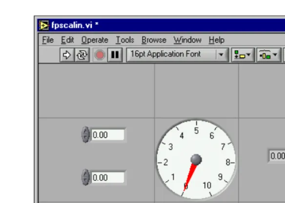
If you set a single front panel object to scale, the object resizes itself automatically in relation to any change in the front panel window size. The other objects on the front panel reposition themselves to remain consistent with their previous placement on the front panel but do not scale to fit the new window size of the front panel.
Figure 4-1. Front Panel with Object Set to Scale When LabVIEW scales objects automatically, it follows the same conventions as when you resize an object manually. For example, some objects can resize only horizontally or vertically, and the font size remains the same when you resize an object.
After LabVIEW automatically scales an object, the object might not scale back to its exact original size when you size the window back to its original position. Before you save the VI, select Edit»Undo to restore the original front panel window and object sizes.
You can set an array to scale or set the objects within an array to scale. If you set the array to scale, you adjust the number of rows and columns you can see within the array. If you set the objects within the array to scale, you always see the same number of rows and columns, though different sizes, within the array.
Adding Space to the Front Panel without Resizing the Window
You can add space to the front panel without resizing the window. To increase the space between crowded or tightly grouped objects, press the <Ctrl> key and use the Positioning tool to click the front panel workspace. While holding the key combination, drag out a region the size you want to insert.
(Mac OS) Press the <Option> key. (Sun) Press the <Meta> key. (Linux)Press the <Alt> key.
A rectangle marked by a dashed border defines where space will be inserted. Release the key combination to add the space.
Front Panel Controls and Indicators
Use the front panel controls and indicators located on the Controls palette to build the front panel. Controls are knobs, push buttons, dials, and other input devices. Indicators are graphs, LEDs, and other displays. Controls simulate instrument input devices and supply data to the block diagram of the VI. Indicators simulate instrument output devices and display data the block diagram acquires or generates.
3D and Classic Controls and Indicators
Many front panel objects have a high-color, three-dimensional appearance. Set your monitor to display at least 16-bit color for optimal appearance of the objects.
The 3D front panel objects also have corresponding low-color,
two-dimensional objects. Use the 2D controls and indicators located on the Classic Controls palette to create VIs for 256-color and 16-color monitor settings.
Slides, Knobs, Dials, Digital Displays, and Time Stamps
Use the numeric controls and indicators located on the Numeric and Classic Numeric palettes to simulate slides, knobs, dials, and digital displays. The palette also includes color boxes and color ramps for setting color values and a time stamp for setting the time and date for the data. Use numeric controls and indicators to enter and display numeric data.
Slide Controls and Indicators
The slide controls and indicators include vertical and horizontal slides, a tank, and a thermometer. Change the value of a slide control or indicator by using the Operating tool to drag the slider to a new position, by clicking a point of the slide object, or by using the optional digital display. If you drag the slider to a new position and the VI is running during the change, the control passes intermediate values to the VI, depending on how often the VI reads the control.
Slide controls or indicators can display more than one value. Right-click the object and select Add Slider from the shortcut menu to add more sliders. The data type of a control with multiple sliders is a cluster that contains each of the numeric values. Refer to the Clusters section of Chapter 10, Grouping Data Using Strings, Arrays, and Clusters, for more information about clusters.
Rotary Controls and Indicators
The rotary controls and indicators include knobs, dials, gauges, and meters. The rotary objects operate similarly to the slide controls and indicators. Change the value of a rotary control or indicator by moving the needles, by clicking a point of the rotary object, or by using the optional digital display.
Digital Controls and Indicators
Digital controls and indicators are the simplest way to enter and display numeric data. You can resize these front panel objects horizontally to accommodate more digits. You can change