MURDOCH RESEARCH REPOSITORY
Agelidis, V.G., Balouktsis, A., Balouktsis, I. and Cossar, C.
(2006) Multiple sets of solutions for harmonic elimination PWM
bipolar waveforms: analysis and experimental verification. IEEE
Transactions on Power Electronics, 21 (2).
pp. 415-421.
Copyright © 2006 IEEE
Personal use of this material is permitted. However, permission to reprint/republish
this material for advertising or promotional purposes or for creating new collective
Multiple Sets of Solutions for Harmonic Elimination
PWM Bipolar Waveforms: Analysis
and Experimental Verification
Vassilios G. Agelidis
, Senior Member, IEEE
, Anastasios Balouktsis, Ioannis Balouktsis, and
Calum Cossar
, Member, IEEE
Abstract—Multiple sets of solutions for the selective harmonic elimination pulse-width modulation method for inverter control exist. These sets present an independent solution to the same problem but further investigation reveals that certain sets may offer an improved overall harmonic performance. In this paper, a minimization method is discussed as a way to obtain these multiple sets of switching angles. A simple distortion harmonic factor that takes into account the first two most significant har-monics present in the generated waveform is considered in order to evaluate the performance of each set. The bipolar waveform is thoroughly analyzed and two cases are considered; single-phase patterns which eliminate all odd harmonics and three-phase counterparts which eliminate only the nontriplen odd harmonics from the line-to-neutral pattern but such harmonics are naturally eliminated from the line-to-line waveform. Experimental results support the theoretical considerations reported in the paper.
Index Terms—Selective harmonic elimination pulse-width mod-ulation (SHEPWM).
I. INTRODUCTION
T
HE elimination of specific harmonics from a given voltagewaveform generated by a voltage-source inverter (VSI) using pulse-width modulation (PWM) has been dealt with in numerous papers [1]–[8]. These methods are known in the tech-nical literature as selective harmonic elimination (SHE) or pro-grammed PWM techniques. Originally, such methods presented solutions regarding the angles that eliminate a number of har-monics [1], [2]. The main challenge associated with such tech-niques is to obtain the analytical solutions of nonlinear transcen-dental equations that contain trigonometric terms which natu-rally exhibit multiple solutions [5]. Other methods do exist, such as the sinusoidal PWM (SPWM) based on a comparison of a ref-erence (sinusoidal) waveform with a carrier (triangular) wave-form offer a specific well controlled spectrum and bandwidth [9] but the focus of this paper is the SHEPWM one only.
Many algorithms have been proposed to deal with the SHEPWM problem. In [3], an algorithm based on two straight
Manuscript received May 20, 2004; revised June 29, 2005. Recommended by Associate Editor J. R. Rodriguez.
V. G. Agelidis was with the Department of Electronics and Electrical Engi-neering, University of Glasgow, Glasgow G12 8LT, U.K. He is now with the School of Engineering Science, Murdoch University, Rockingham 6168, Aus-tralia (e-mail: [email protected]).
A. Balouktsis and I. Balouktsis are with the Department of Informatics and Communications, Technological Education Institution of Serres, Serres, Greece. C. Cossar is with the Department of Electronics and Electrical Engineering, University of Glasgow, Glasgow G12 8LT, U.K.
Digital Object Identifier 10.1109/TPEL.2005.869752
lines with positive and negative slopes that closely approximate the exact solution pattern of the nonlinear equations has been proposed. The starting values for obtaining exact solutions using numerical techniques can be found even for large number of harmonics to be eliminated. Moreover, the close proximity of the starting values to the exact solutions ensures convergence. However, although the letter reports the algorithm and discusses the case of multiple solutions for a three-phase case, it does not report the performance of the said technique against its ability to find all possible solutions. The algorithm seems to be a good approximation for a relatively large number of harmonics to be eliminated.
The performance of these techniques was later analyzed in [4] where the techniques are studied with two systems in mind: the single-phase (line-to-neutral patterns) and three-phase (line-to-line patterns). Specifically, it reported techniques that seek switching angles within 60 and another set that seeks solutions within 90 . However, the paper does not report any different sets of solutions that exist for each case, i.e., for the specific elimination of a given number of harmonics.
A systematic method that makes it possible to solve the HE problem is proposed in [6]. This method is based on a homotopy method which finds multiple solutions for a specific degree of
freedom from those existing for 1 sequentially by the
mathematical induction by varying a fundamental component value as the homotopy parameter. However, the method is long and cumbersome and the paper does not make any contribution toward which set of solutions from the multiple available ones is optimum against overall harmonic performance and presents no experimental results to confirm the analysis.
Recently, a new method to the problem has been reported in [7], where the theory of resultants has been employed to get the solutions for the problem. Specifically, the transcendental equations that describe the harmonic elimination problem are converted into an equivalent set of polynomial equations using trigonometric identities. The theory of resultants is then used to compute the resultant polynomial and then work backward in order to find all unknown, i.e., switching angles. This method also finds all possible sets of solutions. However, the method introduces another step into the problem through the manipu-lation of high order polynomials that their order increases as the number of harmonics to be eliminated also increases. Fur-thermore, it has limited chance to work for a high order of har-monics and it is easy to apply only when such number is low. Moreover, the paper briefly treats the bipolar waveform and only reports the angles to minimize the fifth and seventh harmonics.
416 IEEE TRANSACTIONS ON POWER ELECTRONICS, VOL. 21, NO. 2, MARCH 2006
It confirms though that a second set of solutions exists for this case. Although both sets result in the elimination of the fifth and seventh harmonic, one seems better from the harmonic perfor-mance point of view as it also results in lower value of the first significant harmonic that generates. Finally, it does not discuss how such method performs for the case where the single phase system is considered, i.e., all odd harmonics are eliminated.
In [8], a minimization technique combined with a random search and biased pattern for the initial values and applied di-rectly to the set of the transcendental equations results in all so-lutions of a specified HE problem being obtained in one rela-tively simple step has been reported. The method is of the opti-mization type, and therefore does not seek values for the angles that make the coefficients zero but rather tries to find ones that minimize the function resulting in a more efficient algorithm. This approach could compute angles even beyond the point that other methods do not converge. When physical solutions to the elimination problem do not exist, i.e., in certain overmodulation region, the proposed method can still find the closest alternative angles where the amplitude of such harmonics is as low as pos-sible.
The objective of this paper is to report complete results for the bipolar SHEPWM technique for both single-phase and three-phase converters where all odd harmonics and only the non-triplen odd harmonics are eliminated respectively. The results reported include only the case where quarter and half-wave sym-metry exists for the switching patterns. Moreover, a harmonic distortion factor and the amplitude of the most significant har-monic are studied further in order to identify a potentially better set of solutions if it exists. Selected cases are confirmed experi-mentally and results are presented to support the theoretical ar-guments.
The paper is organized as follows. In Section II, the char-acteristics of the bipolar waveform and the definition of the problem are provided in brief. In Section III, the minimization technique is explained. In Section IV results are presented for
six cases, namely when 2, 4, and 6 where is the number
of harmonics to be eliminated. The first three cases discuss the single-phase systems and the last three cases the three-phase ones. Selected waveforms obtained from laboratory prototypes operating with SHEPWM techniques based on the theoretical work of this paper are presented in Section V to support the ro-bustness of the proposed method. Finally, conclusions of this work are summarized in Section VI.
II. BIPOLAR PWM WAVEFORM FOR
HARMONICELIMINATION
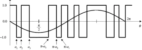
The bipolar SHEPWM technique offers solutions that are suitable either for single-phase or three-phase converters. Fig. 1 shows the waveform and illustrates the problem under
consider-ation. That is, to find appropriate angles where
1 so that the odd harmonics (i.e., third, fifth, seventh,
ninth, 11th, 13th th where 2 1 for single-phase
systems and 3 1 for three-phase systems) are
elimi-nated and control of the fundamental is also achieved. The case where the fundamental frequency component is constant could be also studied [1] but it is beyond the scope of this paper. The method discussed in this paper [8] can also deal with such case.
Fig. 1. Bipolar switching waveform.
The value of the dc bus voltage of the inverter is assumed to be 1 p.u. as shown in Fig. 1.
The SHEPWM technique establishes the Fourier series ex-pansion of the waveform first. This is given in
(1)
The problem then is formulated based on the desired value of the fundamental component to be generated and the method then seeks to find the angles that would provide such amplitude and furthermore would result in the elimination of a number of se-lected harmonics. The waveform shown in Fig. 1 has half-wave and quarter-wave symmetry.
Generalized Case: As stated above, in order to eliminate
odd harmonics, 1 angles need to be found, if possible, and
the following system of equations must be solved:
(2)
where
for single-phase systems (3)
when even for three-phase systems
when odd for three-phase systems
(4)
and
(5)
If is the amplitude of the fundamental component to be
gen-erated then from (1) yields
(6)
It should be noted that for the bipolar waveform when 1
III. PROPOSEDMINIMIZATIONTECHNIQUE
The previously described set of equations must be solved in
order to get the desired values of the angles for any value of .
It is proposed that the following function is minimized first:
(7)
with the constrain that
(8)
The minimization problem to find the first set of solutions for
one value of can be dealt with using a genetic algorithm or the
Nelder–Mead simplex algorithm [8]. The proposed technique in combination with a random search and biased pattern for the initial values finds all the sets of possible solutions for one value
of , i.e., 0.1 and then such information is used as initial
value to find all possible sets of solutions for all values of .
Specifically, for the next value of , the solutions from the
previous value of are used as initial point. At this particular
phase, iterative algorithm such as Newton-Raphson can be used to obtain the desired solutions for the angles. This is done in order to further improve the speed of the method.
The mathematical explanation of the method is beyond the scope of this paper which is aiming only at presenting analysis of the multiple sets and experimental verification. The imple-mentation of the proposed method can be done using a software package such as Mathematica [10].
IV. RESULTS
The method described in Section III has been successfully applied to a number of cases in order to illustrate its robustness. The results for a number of cases are presented and discussed in this Section.
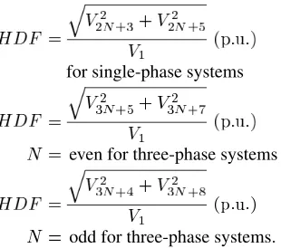
However, first a simple harmonic distortion factor (HDF) is defined as follows:
for single-phase systems (9)
even for three-phase systems
odd for three-phase systems (10)
A. Single-Phase Patterns
Case I: Harmonics to be Eliminated: 3-5: The solutions for this case are presented in Fig. 2(a). There are solutions when
Fig. 2. Case I: Harmonics to be eliminated: 3-5. (a) Switching angles in degrees versusjMj: set 1( )set 2(---) (jMj 0.83). (b) Amplitude of seventh harmonic versusjMj: set 1( )set 2(---). (c) Harmonic distortion factor taking into account the seventh and ninth harmonic versusjMj: set 1 ( )set 2(---). (d) Switching waveform forM = 00.5. (e) Switching waveform forM =0.5.
0.83. Since there are two clear sets, the seventh har-monic is also plotted in Fig. 2(b) in order to study the perfor-mance of each set against the first significant harmonic gener-ated. The respective HDF is plotted in Fig. 2(c). It is shown that there is no clear benefit for choosing one set against the other as both techniques would result in similar distortion when the first two significant harmonics are taken into account. However, for a narrow range, at high modulation index, one method results in lower distortion and this may offer a benefit, but this is con-sidered marginal. In order to illustrate the phase-shifting result
of the negative value of , the two waveforms are plotted in
Fig. 2(d) 0 and Fig. 2(e) 0 .
Case II: Harmonics to be Eliminated: 3-5-7-9: There are
also two sets of solutions for this case for 0.8 [Fig. 3(a)].
The 11th harmonic is plotted in Fig. 3(b) indicating very little difference between the two sets. The HDF shown in Fig. 3(c) confirms the same point.
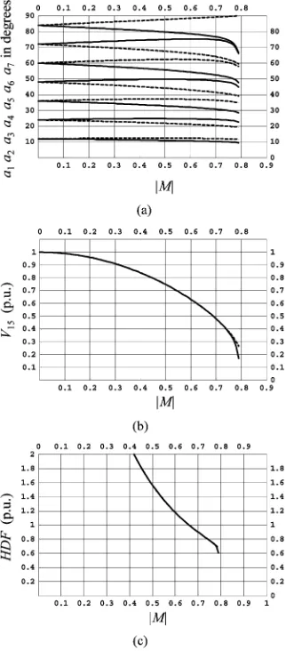
Case III: Harmonics to be Eliminated: 3-5-7-9-11-13: Likewise, there are two sets for 0.79 [Fig. 4(a)]. Once again there is no difference between the two sets when the amplitude of the 15th harmonic is taken into account [Fig. 4(b)] along with the HDF [Fig. 4(c)].
B. Three-Phase Patterns
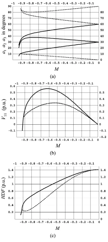
Case IV: Harmonics to be Eliminated: 5–7: The switching angles for the said harmonics to be eliminated are plotted in Fig. 5(a). It is confirmed that the proposed elimination method finds all set of solutions for this specific waveform and solutions
exist only when is negative. No solution exists which results
418 IEEE TRANSACTIONS ON POWER ELECTRONICS, VOL. 21, NO. 2, MARCH 2006
Fig. 3. Case II: Harmonics to be eliminated: 3–5–7–9. (a) Switching angles in degrees versusjMj: set 1( )set 2(---) (jMj 0:8). (b) Amplitude of 11th harmonic versusjMj: set 1( )set 2(---). (c) Harmonic distortion factor taking into account the 11th and 13th harmonic versusjMj.
0.93 (set 1) and 0.91 (set 2). Clearly there are
two sets of solutions throughout all values of (set 1: , set
2: ---). It is therefore important that the optimum one is identi-fied with respect to harmonic performance. It is clear that the set 2 --- offers a better harmonic performance and this has also been reported in [7]. To illustrate this even further, the ampli-tude of the first nontriplen odd significant harmonic present in the generated waveform is plotted in Fig. 5(b) for both sets for
all values of . Once again set 2 --- results in lower
ampli-tude of such harmonic further indicating that it is better than set
1 for all values of . The HDF is plotted in Fig. 5(c) to confirm
the same finding.
Case V: Harmonics to be Eliminated: 5–7–11–13: The switching angles for the said harmonics to be eliminated are plotted in Fig. 6(a) and (b). It is important to note that the proposed minimization method finds all sets of solution. In this case, there are two sets of solutions throughout all values of
when 0.91 0 (set 1: , set 2: ---) and two more for
0 0.91 (set 3: , set 4: ---). Once again no solution
exists when 0.91 or 0.91. The amplitude of the
first nontriplen odd significant harmonic (i.e., 17th) present in the generated waveform is plotted in Fig. 6(c) for all sets for all
values of . Sets 3 and 4 result in a lower amplitude of such
Fig. 4. Case III: Harmonics to be eliminated: 3–5–7–9–11–13. (a) Switching angles in degrees versusjMj: set 1( )set 2(---) (jMj 0.79). (b) Amplitude of 15th harmonic versusjMj: set 1( )set 2(---). (c) Harmonic distortion factor taking into account the 15th and 17th harmonic versusjMj: set 1( )set 2(---).
harmonic further indicating their potential to perform better
overall throughout the complete region of . The HDF is
plotted for both negative and positive values of [Fig. 6(d)].
It is found that set 2, set 3, and set 4 perform better than set 1.
Case VI: Harmonics to be Eliminated: 5–7–11–13– 17–19: In this case seven angles are sought in order to eliminate the above mentioned harmonics from the waveform. It is interesting to note that the solutions for the switching angles form a number of sets. Specifically, there are four independent sets of solutions that eliminate these harmonics
only for negative values for . No solution can be found for
positive values of . The amplitude of the first nontriplen odd
harmonic, i.e., the 23rd is also plotted for all values of and
for all four sets in Fig. 4(c). It is confirmed that set 3 seems slightly better than all others. The HDF factor is plotted in Fig. 7(d). Although each set of solutions provides a different performance, it is also clear that set 3 [Fig. 7(d)] offer almost similar performance and are clearly better than the other two sets.
Finally, in order to illustrate the effect of on the solutions,
in Fig. 8 all possible PWM switching patterns are generated for
Fig. 5. Case IV: Harmonics to be eliminated: 5–7. (a) Switching angles in degrees versusM: Set 1( ) (M 00.93). Set 2(---) (M 00.91). (b) Amplitude of the 11th harmonic (p.u.) versusM: set 1( )set 2(---). (c) Harmonic distortion factor taking into account the 11th and 13th harmonic versusM: set 1( )set 2(---).
set 3 0.5 and set 4 0.5 . As previously mentioned,
the value of implies that the resulting solutions generate a
PWM waveform without the eliminated harmonics but also with
a phase difference of 0 0 or 180 0 .
V. EXPERIMENTALVERIFICATION
Selected results have been verified experimentally, especially concerning the harmonic spectrum of waveforms with the angles specified by the proposed method. These results are presented in Figs. 9 and 10. Specifically, for Case V: Harmonics
to be eliminated 5–7–11–13: and for | | 0.5, there are four
sets of solutions. These waveforms have been plotted using computer software in Fig. 9. For each set, the resulting PWM switching waveform is plotted along with the spectrum. It is clear that the experimental waveforms are in agreement with the simulated ones, constitute four independent sets as predicted theoretically and have only triplen odd harmonics within the band where the nontriplen ones are eliminated. Finally, these
waveforms are applied across an inductive load ( 10 mH
and 2.5 ) in order to study the load currents. In Fig. 10,
Fig. 6. Case V: Harmonics to be eliminated: 5–7–11–13. (a) Switching angles in degrees versusM(00.91 M 0); Set 1( ). Set 2(---). (b) Switching angles in degrees versusM(0 M 0.91); Set 3( ). Set 4(---). (c) Normalized amplitude of the 17th harmonic (p.u.) versusjMjfor all sets. (d) Harmonic distortion factor taking into account the 17th and 19th harmonic versusjMjfor all sets (set 1( )set 2(--)set 3(-- --)set 4(--- ---)).
Fig. 7. Case VI: Harmonics to be eliminated 5–7–11–13–17–19. (a) Switching angles in degrees versusM(00.91 M 0); set 1( )set 2(--). (b) Switching angles in degrees versusM(00.91 M 0); set 3( )set 4 (--). (c) Amplitude of the 23rd harmonic for all sets versusM; set 1( )set 2(--)set 3(-- --)set 4(--- ---).(d) Harmonic distortion factor taking into account the 23rd and 25th harmonic versusM; for set 1( )set 2(--)set 3 (-- --)set 4(--- ---).
the current waveforms along with their spectrum for all sets are presented. Inspecting these results indicates that set three offers a solution that generates the lowest 17th harmonic and for this operating point, it is beneficial to use it. Such superior performance by one set of solutions may not be maintained within the complete range of the modulation index and this needs to be studied for each case separately.
420 IEEE TRANSACTIONS ON POWER ELECTRONICS, VOL. 21, NO. 2, MARCH 2006
Fig. 8. Case V: Harmonics to be eliminated: 5–7–11–13. (a) PWM switching pattern for set 1 andM = 00.5. (b) PWM switching pattern for set 2 and M = 00.5. (c) PWM switching pattern for set 3 andM =0.5. (d) PWM switching pattern for set 4 andM =0.5.
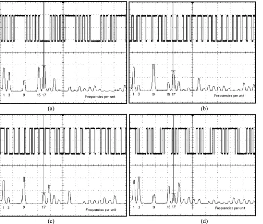
Fig. 9. Case V: Harmonics to be eliminated: 5–7–11–13 (50 V/div, fundamental frequency 25 Hz and cursor at 425 Hz, i.e., 17th). (a) PWM switching pattern and associated harmonic spectrum for set 1 andM = 00.5. (b) PWM switching pattern and associated harmonic spectrum for set 2 and M = 00.5. (c) PWM switching pattern and associated harmonic spectrum for set 3 andM =0.5. (d) PWM switching pattern and associated harmonic spectrum for set 4 andM =0.5.
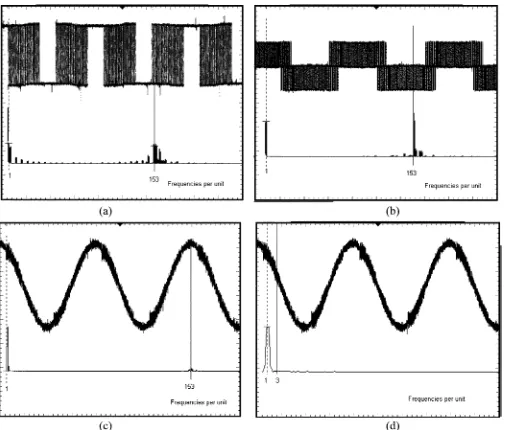
is the 103rd harmonic at 2.575 kHz confirming the theory. The current confirms the same and it is shown in Fig. 11(b).
Fig. 12 shows the performance of the SHEPWM technique for a three-phase case where the first 50 nontriplen odd har-monics are eliminated from the line-to-neutral PWM switching [Fig. 12(a)]. This solution is randomly taken from a large pool of acceptable ones. The line-to-line voltage has no triplen harmonic and the first one is located at 153rd harmonic, i.e., 3825 Hz as predicted [Fig. 12(b)]. Finally, the line current of the load is also presented in Fig. 12(c) to prove the performance of the method. A close up of the low frequency harmonic spectrum shown in Fig. 12(d) indicates that no third harmonic exists (base frequency 25 Hz, cursor at 75 Hz third with zero amplitude).
Fig. 10. Case V: Harmonics to be eliminated: 5–7–11–13 (5 A/div, fundamental frequency 25 Hz and cursor at 425 Hz, i.e., 17th). (a) Line current and associated harmonic spectrum for set 1 andM = 00.5. (b) Line current and associated harmonic spectrum for set 2 andM = 00.5. (c) Line current and associated harmonic spectrum for set 3 andM =0.5. (d) Line current and associated harmonic spectrum for set 4 andM =0.5.
Fig. 11. Single-phase pattern to eliminate the first 50 odd harmonics (50 V/div, 5 A/div, fundamental frequency 25 Hz and cursor at 2.575 kHz i.e., 103rd harmonic). (a) PWM switching pattern (showing a quarter of the period) and associated harmonic spectrum for set 1 andM = 00.5. (b) Line current and associated harmonic spectrum for set 1 andM = 00.5.
VI. CONCLUSION
Fig. 12. Three-phase pattern to eliminate the first 50 nontriplen odd harmonics (50 V/div, 5 A/div, fundamental frequency 25 Hz and cursor at 3825 Hz, i.e.,153rd harmonic). (a) PWM switching pattern and associated harmonic spectrum for one set andM = 00.5 including third harmonic and multiples. (b) Line-to-line voltage waveform and spectrum free from third harmonic and multiples. (c) Line current and associated harmonic spectrum for one set andM = 00.5. (d) Line current and associated harmonic spectrum for one set andM = 00.5 (low frequency zoom in spectrum cursor at 75 Hz, i.e., third harmonic having zero amplitude).
REFERENCES
[1] H. S. Patel and R. G. Hoft, “Generalized harmonic elimination and voltage control in thyristor inverters: Part I—harmonic elimination,”
IEEE Trans. Ind. Applicat., vol. IA-9, no. 3, pp. 310–317, May/Jun. 1973.
[2] , “Generalized harmonic elimination and voltage control in thyristor inverters: part II—voltage control technique,”IEEE Trans. Ind. Applicat., vol. IA-10, no. 5, pp. 666–673, Sep./Oct. 1974. [3] P. Enjeti and J. F. Lindsay, “Solving nonlinear equations of harmonic
elimination PWM in power control,”Electron. Lett., vol. 23, no. 12, pp. 656–657, Jun. 1987.
[4] P. N. Enjeti, P. D. Ziogas, and J. F. Lindsay, “Programmed PWM tech-niques to eliminate harmonics: A critical evaluation,”IEEE Trans. Ind. Applicat., vol. 26, no. 2, pp. 302–316, Mar./Apr. 1990.
[5] T. Kato, “Precise PWM waveform analysis of inverter for selected harmonic elimination,” inProc. IEEE Industry Applicat. Soc. Annu. Meeting, 1986, pp. 611–616.
[6] , “Sequential homotopy-based computation of multiple solutions for selected harmonic elimination in PWM inverters,”IEEE Trans. Cir-cuits Syst. I, vol. 46, no. 5, pp. 586–593, May 1999.
[7] J. Chiasson, L. M. Tolbert, K. McKenzie, and Z. Du, “A complete solu-tion to the harmonic eliminasolu-tion problem,”IEEE Trans. Power Electron., vol. 19, no. 2, pp. 491–499, Mar. 2004.
[8] V. G. Agelidis, A. Balouktsis, and I. Balouktsis, “On applying a min-imization technique to the harmonic elimination PWM control: The bipolar waveform,”IEEE Power Electron. Lett., vol. 2, no. 2, pp. 41–44, Jun. 2004.
[9] A. Shonung and H. Stemmler, “Static frequency changers with “subhar-monic” control in conjunction with reversible variable-speed ac drives,”
Brown Boveri Rev., vol. 51, pp. 555–557, 1964.
[10] Mathematica 5.0, Wolfram Research Inc., Champaign, IL, 2005.
Vassilios G. Agelidis(SM’00) was born in Serres, Greece. He received the B.S. degree in electrical engineering from Democritus University of Thrace, Thrace, Greece, in 1988, the M.S. degree in applied science from Concordia University, Montreal, QC, Canada, in 1992, and the Ph.D. degree in electrical engineering from the Curtin University of Tech-nology, Perth, Australia, in 1997.
From 1993 to 1999, was with the School of Elec-trical and Computer Engineering, Curtin University of Technology. In 2000, he joined the University of Glasgow, Glasgow, UK, as a Research Manager for the Centre for Economic Re-newable Power Delivery. In addition, he has authored/coauthored several journal and conference papers as well asPower Electronic Control in Electrical Sys-tems(2002). In January 2005, he was appointed as the inaugural Chair of Power Engineering in the School of Engineering Science, Murdoch University, Perth, Australia, to lead a world class education and research centre in power engi-neering including a new undergraduate/postgraduate and industrial training and professional development program.
Dr. Agelidis received the Advanced Research Fellowship from the Engi-neering and Physical Sciences Research Council (EPSRC) in 2004. He is the Vice President Operations within the IEEE Power Electronics Society. He was an Associate Editor of the IEEE POWERELECTRONICSLETTERSsince 2003, and served as the PELS Chapter Development Committee Chair from 2003 to 2005. He will be the Technical Chair of the 39th IEEE PESC’08, Rhodes, Greece.
Anastasios Balouktsis received the B.S. degree in electrical/mechanical engineering and the B.S. degree in mathematics from Aristotle University of Thessaloniki, Greece, in 1978 and 1982, respec-tively, and the Ph.D. degree in electrical engineering from Democritus University of Thrace, Xanthi, Greece, in 1986.
From 1978 to 1981, he was a volunteer at the Hel-lenic Air Forces. From 1981 to 1986, he was a Re-search Technologist and from 1987 to 1990 a Lec-turer at the Department of Electrical and Mechanical Engineering, Democritus University of Thrace. Since 1990, he has been a Pro-fessor at the Technological Educational Institution of Serres, Greece (TEI). He has been elected as the Head of School of Applied Technology and has been Vice President and President of the Institution (TEI). He is the author/coauthor of many scientific papers in various disciplines and his technical interests include renewable energy sources, power systems, power electronics, digital electronics and mathematics.
Dr. Balouktsis is a member of the Professional Engineers of Greece.
Ioannis Balouktsis received the B.S. degree in electrical and electronic engineering from Cardiff University, Wales, UK, in 2003 and the M.S. degree in electrical and electronic engineering from Strath-clyde University, Glasgow, UK, in 2004.
Since 2004, he has been a Research Scientist with the Technological Educational Institution of Serres, Serres, Greece. His research interests include power electronics, automatic control, digital electronics, and renewable energy systems.
Calum Cossar(M’90) was born in Hamilton, U.K. He received the B.Sc. (with honors) degree in elec-trical and electronic engineering from the University of Glasgow, Glasgow, U.K., in 1983.