doi:10.5194/ars-10-167-2012
© Author(s) 2012. CC Attribution 3.0 License.
Radio Science
A design study on complexity reduced multipath mitigation
U. Wasenm ¨uller1, T. Brack1, I. Groh2, E. Staudinger3, S. Sand3, and N. Wehn1 1Microelectronic Systems Design Research Group, University of Kaiserslautern, Germany 2Intel Mobile Communications, Germany
3Institute of Communications and Navigation, German Aerospace Center (DLR), Germany Correspondence to: U. Wasenm¨uller ([email protected])
Abstract. Global navigation satellite systems, e.g. the cur-rent GPS and the future European Galileo system, are fre-quently used in car navigation systems or smart phones to de-termine the position of a user. The calculation of the mobile position is based on the signal propagation times between the satellites and the mobile terminal. Further, the satellites need to be line-of-sight to the receiver for exact position cal-culation. However, in an urban area, the direct path may be blocked and the resulting multipath propagation causes er-rors in the order of tens of meters for each measurement.
In this paper an advanced algorithm for multipath miti-gation known as CRMM is presented. CRMM features re-duced algorithmic complexity and superior performance in comparison with other state of the art multipath mitigation al-gorithms. Simulation results demonstrate the significant im-provements in position calculation in environments with se-vere multipath propagation. Nevertheless, in relation to tradi-tional algorithms an increased effort is required for real-time signal processing due to the large amount of data, which has to be processed in parallel. Based on CRMM, we performed a comprehensive design study including a design space ex-ploration for the tracking unit hardware part, and prototype implementation for hardware complexity estimation.
1 Introduction
Currently, personal navigation devices (PNDs) and smart-phones are widely used for car and pedestrian navigation or location based services (LBS). These devices employ mass market global navigation satellite systems (GNSSs) re-ceivers, e.g. for the current GPS and GLONASS or the fu-ture European Galileo system. A GNSS receiver determines its position uniquely by measuring and calculating the nal propagation time from at least four different satellite sig-nals. State-of-the-art mass market GNSS receivers measure and track the time of arrival (TOA) of the satellite signals
with narrow early-minus-late (NEML) delay-locked loops (DLLs). NEML DLLs result in the optimum TOA estimates when there is a direct line-of-sight (LOS) between the satel-lite and GNSS receiver and the signal reception is not dis-turbed by multipath propagation.
Often, LBS are used in cities where the satellite signals are subject to diffraction, refraction, and scattering result-ing in multipath propagation. Thus, the positionresult-ing accuracy of state-of-the art mass market GNSS receivers with NEML DLLs will be degraded from a few meters to several tens of meters. In van Nee et al. (1994), maximum likelihood (ML) multipath estimation (ME) algorithms can mitigate these er-rors but are computationally too expensive for mass market GNSS receivers in terms of computing power and power con-sumption. Consequently, Selva (2004, 2005) developed com-plexity reduced multipath mitigation (CRMM) algorithms that employ a bank of correlators to reduce the amount of data that needs to be handled by the MLME. Several publi-cations on CRMM discuss various implementation aspects of the algorithm, e.g. Groh and Sand (2008); Groh et al. (2011); Groh and Sand (2012). However, none provides a more de-tailed analysis with respect to real-time or hardware imple-mentation issues.
In Sect. 2 we show the used system model and in Sect. 3 the considered CRMM algorithm is summarized. In Sect.4 the design study including design space exploration for the tracking unit hardware part and prototype implementation for hardware complexity estimation is presented, and in Sect. 5 the results are summarized.
2 System model and MLME
Fig. 1. GNSS satellite visibility in a Munich urban environment.
0 50 100 150 200 250 300
0 5 10 15 20 25 30 35 40
Time−step of track
RMSE [m]
GNSS
GNSS, CRMM−ML
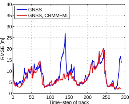
Fig. 2. RMSE vs. time-step of track for GNSS with NEML and
CRMM-ML.
sequence spread spectrum transmit signal is then
s(t )=
M−1 X
m=0 dP,m
N−1 X
n=0
cP,ng(t−mT−nTC),
+
M−1 X
m=0 dD,m
N−1 X
n=0
cD,ng(t−mT−nTC) (1)
whereT =N TC andTC=1/RCdenote the spreading code duration and chip duration with RC being the chip rate. The pilot and data symbol sequences dP,m anddD,m, m=
0,...,M−1 are taken from quartenary phase shift keying modulation. M codewords form the considered time in-terval for MLME. The spreading code sequencescP,n and
cD,n,n=0,...,N−1 for the pilots and data are pseudo-noise
sequences of lengthNas defined in EUG (2010). In order to obtain a suitable matrix vector factorization beginning from Eq. (1), we choose the sampling frequencyfSas integer
mul-Fig. 3. Arcitecture of Tracking unit.
Fig. 4. Arcitecture of Code NCO and PRN unit.
tiple of the chip rate RC yielding Q=fS/RC samples per chip.
In order to demonstrate the influence of the multipath propagation on the estimation performance of the LOS path and thereby on the position estimation of the mobile station, the channel is modelled as a fixed channel of lengthL
h(τ,t )=h(τ )=
L X
`=1
a`δ(τ−τ`). (2)
where the number of channel coefficientsLis assumed to be known to the receiver.a`andτ`are the amplitude and delay
of the`-th multipath component. Note thatl=1 corresponds to the LOS component. The TOAτ1is related to the distance between thei-th satellite and the receiver asdi=cτ1withc being the speed of light.
After transmission over the channel (cf. Eq. 2), we obtain the complex valued baseband-equivalent received signal as
y(t )=
L X
l=1
als(t−τl)+n(t ), (3)
wheres(t )is the navigation signal transmitted by the satellite andn(t )∼Nc 0,σn2
Table 1. Detailed assumptions and platform properties.
Description Parameter Type of FPGA Stratix II EP2S180F1020C3
ALUTs 143 520
Dedicated Logic Registers 143 520 DSP Block Resources 96 Block Memories 930 M512, 768 M4K Processing clock speed (fclk) 100 MHz Sample Clock (fs) 16.8 Msps (Complex Data) ADC Output Quantisation 3 bit
Table 2. CWO complexity estimation.
Element Parameter Nr. ALUT DREG SIN/COS-LUT 8×6 bit 1 6 6 Multiplier 3×3 bit 2 12 6 Phase Accumulator 32 bit 1 0 32 Phase Adder 32 bit 1 32 0 Phase Error Adder 32 bit 1 32 32
Overall 82 76
Gaussian noise (AWGN) of the power σn2=E| n(t )2|
. Samplingy(t ), we obtain the receive signal vector
y=
L X
`=1
a`s(τ`)+n=S(τ)a+n∈CMN Q, (4)
where S(τ) = [s(τ1),...,s(τL)] ∈ CMN Q×L and a= [a1,...,aL]T ∈CL form the signal matrix and the amplitude vector. The SNRγ is defined according to Eq. (4) asγ= kS(τ)ak2
2/ MN Qσn2
.
The MLME{ ˆa,τˆ} ∈CL is given according to Lentmaier and Krach (2006) by
{ ˆa,τˆ} = argminky−S(τ)ak2
2,
{a,τ} (5)
where the first elementτˆ1inτˆdenotes the TOA ML estimate. The received signal vectory may containM=10 symbols andN=4092 chips per symbol withQ=16 samples per chip. Thus, the optimization algorithm for Eq. (5) has to process more than 650 000 samples received within 40 ms, which is prohibitive in terms of computational complexity and power consumption for a mass market GNSS receiver.
3 CRMM
To overcome the computational complexity of Eq. (5), Selva (2004, 2005) developed the basic CRMM algorithm, which implements the following two steps:
– Data size reduction: the large received signal vector y is transformed by a bank of correlators into a much
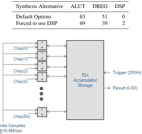
Table 3. CWO synthesis results.
Synthesis Alternative ALUT DREG DSP Default Options 83 51 0 Forced to use DSP 69 39 2
Fig. 5. Integrate and Dump unit.
smaller vector yc before the ML optimization. The subspace transform results in maximum data compres-sion and negligible performance losses. For instance, the observation vectorycan be reduced from hundred thousands of samples toycwith a few tens of samples Groh and Sand (2008).ycan be compressed with code matched correlators (CMCs), signal matched correla-tors (SMCs) and principal components (PCs) or through combining either CMCs or SMCs with subsequent PCs (cf. Lentmaier and Krach, 2006; Groh and Sand, 2008, 2012). Note, in this paper we only focus on SMCs. – ML optimization: efficient and robust Newton-type
op-timization algorithms were developed. These algo-rithms employ interpolation methods to allow arbitrary delay resolution independent of the sampling rate. Modifications of the CRMM include extension of data size reduction to time-variant signals (Groh et al., 2011), opti-mized correlator computation (Groh and Sand, 2012), and replacement of the Newton-type optimization with expecta-tion maximizaexpecta-tion or space alternating general expectaexpecta-tion maximization algorithms (Groh and Sand, 2008).
In this paper, the focus is on the data size reduction of CRMM and its realizability in hardware in the subsequent sections. Whereas the correlator input y receives samples with ratefS, the correlator can output the samples ofycwith rates between 1000 Hz to 1Hz depending onMandN. Thus, clearly subsequent complexity reduction or ML optimization will be less critical for hardware implementation.
Table 4. NCO and PRN generator complexity estimation.
Element Parameter Nr. ALUT DREG NCO-Divider 32 bit by 12 bit 1 48 48 Correlator Banks 51×32 bit 1 25 32 Phase Accumulator 32 bit 1 0 32 Phase Adder 32 bit 1 32 0 Phase Error Adder 32 bit 1 32 32 Correlator Adder (large) 51×32 bit 1 800 0 Correlator Adder (small) 51×12 bit 1 36 0 E1B/E1C Code Storage 4092×2 bit 3 480 0 Output Registers 2×1 bit 51 0 102
Overall 1453 246
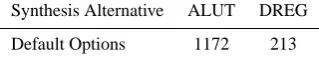
Table 5. NCO and PRN generator synthesis results.
Synthesis Alternative ALUT DREG Default Options 1172 213
canyon scenario in Munich with average building height of 26 m. For at least four LOS satellites, the track is colored green, which is the minimum number of LOS satellites to obtain a reliable position.
Figure 2 shows the corresponding root-mean-square error (RMSE) of the position estimate in meter versus the time-step of the track in Fig. 1. The RMSE was averaged over the same track with the same satellite constellation and ur-ban scenario for 1000 noise realizations. Comparing Figs. 1 and 2, the main error source for the time-steps 20 to 85 and 180 to 255 is due to less than four available LOS satellite sig-nals. On the other hand, the major error source at the start, for time-steps 125 to 145, and at the end is due to multipath propagation although there should be at least four LOS satel-lite signals available. At these time-steps, CRMM can reduce the RMSE absolute by 7.5 m to 20 m and relative by 200 % to 650 %.
4 Prototype architecture design exploration
In the GREAT project, we investigated in detail through simulations the performance of CRMM, which is superior to most simple correlators based multipath mitigation algo-rithms (Hu et al., 2008). CRMM requires a large number of correlators per satellite to transform the multipath mitigation into a lower dimensional sub-space. A first complexity anal-ysis in GREAT showed that based on the floating point opera-tions per second, CRMM has a comparable complexity with classical correlators based multi-path mitigation algorithms (Hu et al., 2008). From GREAT, the question remained open, whether it would be feasible to implement CRMM in hard-ware for instance in a COTS FPGA. The following study
ad-Table 6. I&D unit complexity estimation.
Element Parameter Nr. ALUT DREG Adder 23 bit 51 1173 0 Accumulator Storage 51×23 bit 2 0 2346
Overall 1173 2346
Fig. 6. Timing for alternative architecture of I&D unit.
dresses this question in more detail with the requirement of 51 integrate and dump units.
4.1 Design drivers and top level architecture
Besides the acquisition unit, the tracking unit of GNSS receivers is by far the most complex receiver part which requires high-speed processing on dedicated hardware re-sources. Primary goal of the prototyping approach was to derive a preliminary architecture design for feasibility study and to acquire complexity estimation data for the tracking unit based on a given FPGA target platform. Detailed as-sumptions and platform properties are listed in Table 1.
Table 7. I&D unit complexity estimation (curled-up).
Element Parameter Nr. ALUT DREG
Adder 23 bit 11 253 0
Accumulator Storage 51×23 bit 2 0 2346
Multiplexer 11:1 5×23 805 0
De-Multiplexer 11:1 5×23 805 0
Overall 1863 2346
generator”, and the “Dual Channel Correlation and Discrim-inators”.
Each architecture unit is considered separately in the next sections. Residual elements depicted in the top level ar-chitecture (Multipliers, Registers), glue logic, and the main FSM is considered in the final complexity estimation with an adequate lump-sum estimate.
4.2 Carrier Wipe-Off (CWO)
The CWO unit is responsible for removing the carrier of the ADC input signal by mixing this signal with a synthetically generated carrier using the estimated frequency and phase from the acquisition and tracking components. Based on the assumptions of a 3-bit ADC input at 16.8 Msps, a 6-bit output signal with the same rate has to be generated by this unit. The basic architecture derived from the available SIMULINK model uses a so called Direct Digital Synthesizer (DDS) to generate the required complex continuous wave signal, mix-ing is done by per-component multiplication of the complex input signal with the generated signal. The DDS uses a phase accumulator and a sine/cosine Lookup-Table (LUT) for sig-nal generation: A 32-bit phase accumulator was employed to achieve a frequency resolution of 0.023 Hz which is ade-quate for the used algorithm, the LUT resolution was set to 3 bit to be compatible with the input resolution. In a first step, the hardware complexity of the individual architecture components was calculated to allow for plausibility checks after synthesis. Note that the control FSM for the unit was not considered in this calculation.
In a second step, the architecture was realized in VHDL and synthesized in the Quartus-II tool suite for the appropri-ate FPGA target. As an alternative, the synthesis tool was forced to apply DSP blocks for the design.
Both alternatives result in a very small core requiring< 1 % of the full FPGA resources. To further reduce complex-ity, the architecture could be “curled up” to process only one sample every 5 clock cycles with the assumed clock speed of 100 MHz. This two-step approach with preliminary calcu-lation based on architecture components followed by imple-mentation and synthesis is also used for the remaining units.
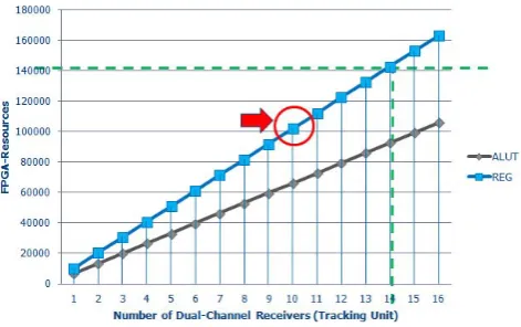
Fig. 7. Final results.
4.3 Code NCO and PRN generator unit
The Code NCO and PRN generator unit is utilized to generate a chip-sequence based on the given chip-rate for 1.023 MHz, the estimated code phase and the channel codes and correlators themselves. This unit accepts 32bit code-phase inputs in 4 ms intervals, yielding an input data rate of only 250 Hz. The outputs of the generator are 51bit code words for both E1B and E1C channels (so called replica val-ues) at 16.8 Mcodes per second.
The architecture uses a DDS as introduced in the CWO unit to generate code phases at the chip rate of 1.023 MHz with an adjustable phase from the phase estimation. The fre-quency resolution is also set to 0.023 Hz, so a 32bit quanti-sation is derived for the phase input and accumulator.
The hardware complexity for the architecture building blocks are estimated and calculated accounting for the sym-metry and actual values of the provided correlators and the resulting code index values. It is determined that instead of 51 different code index values, only three actually occur given these parameters. All these properties result in the very compact Correlators Bank, Correlation Adders, and Code Storage, cf. Table 4. The synthesis results for the VHDL implementation confirm the preliminary complexity results and even undercut the estimation, cf. Table 5.
The core resembling the Code NCO and PRN generator unit utilizes <1 % of the full FPGA resources. Same as for the CWO unit, the architecture could be “curled up” to exploit the difference between sample rate and processing speed and further reduce the complexity. It is noteworthy that for different correlators and codes, the resulting complexity could be more than 10 times higher.
4.4 Dual Channel Correlation and Discriminators unit
Table 8. I&D unit complexity estimation (RAM-based).
Element Parameter Nr. ALUT DREG MEM Adder 23 bit 11 253 0 0 Adder Registers 23 bit 11 0 253 0 Accumulator Storage 8×23 bit 11×2 0 0 2530 bit Overall 253 253 2530 bit
Table 9. I&D unit synthesis results (4 units).
Synthesis Alternative ALUT DREG M512 M4K Default Options 4692 9384 0 0 Curled-Up 7452 9384 0 0 RAM-based (Auto-Fit) 1068 1068 4 60 RAM-based (Forced to use M512) 1068 1068 120 0
curled up realization or even the utilization of a general pur-pose processor like the NIOS-II. Using such a processor, up to 400 000 clock cycles are available to achieve one PLL or DLL result. Alternatively, multiple dual-channel GNSS re-ceivers could share one PLL/DLL processor resource. For all these reasons, the prototyping approach only considers the four I&D units inside the Dual Channel Correlation and Discriminators unit. These units require dedicated hardware resources because of their relatively high input data rate of 16.8 MSps and large-volume data storage. Each I&D unit has to accept the 6bit receiver data coming from the CWO unit at 16.8 Msps (I or Q component) and the 51bit wide code words coming from the Code NCO and PRN generator unit at the same rate. The I&D unit basically multiply-accumulates the incoming data streams 67 200 times which is derived from the ratio between the 16.8 Msps sampling rate and the 250 symbol rate which also constitutes the output rate. There-fore, for each accumulator storage word 23bit are required (6bit + log2(67 200)>22bit). This task can be fulfilled by straight forward architecture shown in Fig. 5.
The complexity of the building blocks can be calculated from the two main building blocks of this approach, the adders and the accumulator storage itself (Table 6). To adapt for the very slow output data rate, a second “shadow stor-age” will be mandatory. This shadow storage keeps the last accumulation result until it can be transferred to the post-processing stages (PLL/DLL) and allows the continuous ac-cumulation of newly arriving input data.
This first estimate (multiplied by 4 to get the result for the whole receiver) would already utilize≈7% of the complete FPGA. To reduce complexity, a “curled-up” architecture us-ing the rate difference between processus-ing clock (100 MHz) and data rate (16.8 Msps) was developed and analyzed. This architecture accepts 11 input samples per clock cycle instead of the 51. The timing for this “curled up” architecture is shown in Fig. 6.
Rough calculation of this alternative architecture (cf. Ta-ble 7) yielded even worse resource efficiency than the straight forward approach: the accumulator storage still consists of 2 large register banks, additionally Multiplexers and De-Multiplexers are now required to direct the 11 I/Os to the 51 storage locations.
Further investigations into the “curled-up” architecture were performed to reduce the required register resources (DREGs) and the introduced multiplexers and demultiplex-ers at the same time. To achieve this goal, the 51×23bit accumulator registers had to be mapped onto the dedicated RAM resources available in the Stratix-II FPGA: M512 (32×18bit) and M4K (128×36bit).
This approach requires only very limited additional logic for the adders; the multiplexers and demultiplexers are al-ready available inside the memories addressing capability. For the accumulator storage, a memory depth of 8 was cho-sen to accommodate for the actually required depth of 5 words. The memories themselves were selected to be “sim-ple dual-ported”, therefore read and write accesses can occur at the same time, but not on the same word. All three alterna-tives have been implemented in VHDL and synthesized. For the RAM-based approach, even an option to force the syn-thesis to use only the M512 memory resources to increase efficiency in memory utilization was applied. Table 9 shows the results for the Dual Channel Correlation and Discrimina-tors unit, therefore 4 I&D units were considered.
Table 10. Combined implementation results.
Unit Alternative ALUT DREG CWO Default 82 (1 %) 76 (1 %) Code NCO and PRN gen. Default 1172 (18 %) 213 (2 %) DCC and Discriminators Default 4896 (74 %) 9384 (92 %) Residue, Glue Logic, FSM Estimate 500 (7 %) 500 (7 %)
Overall 6650 10 173
5 Prototype complexity estimation
The implementation results presented in detail in the pre-vious section are now combined to yield the complexity estimation for the complete duchannel receiver. As al-ready explained before, residual elements, glue logic and the main FSM are introduced as a lump sum estimate only: 500 ALUTs and 500 DREGs are assumed to cover the required resources even for worst-case scenarios.
The combined implementation results for the stated alter-natives (see Table 10 and Fig. 7) add up to 6650 ALUTs and 10173 DREGs which amounts to ≈4.6% and ≈7.0% re-spectively of one complete Stratix-II FPGA.
In conclusion, up to 14 dual-channel receivers could be theoretically realized on the given FPGA platform incorpo-rating all assumptions and limitations made for this receiver prototyping approach. Because of timing and place and route (P&R) limitations, up to 10 full receivers should be feasi-ble. By using the RAM-based approach for the realization of the Dual Channel Correlation and Discriminators unit, the results are not changed significantly: For one dual-channel receiver 7.8 % of the M4K or 12.9 % of the M512 resources of the given FPGA will be required and therefore become the bottleneck. However, if multiple receivers have to be deployed on the same FPGA, the different implementation styles can have massive effects on the scalability of the over-all design, especiover-ally in terms of timing and P&R. The imple-mentation complexity of the PLL/DLL as well as the acqui-sition block and all required internal and external interfaces should also be analyzed to further substantiate these findings.
References
EUG: European GNSS (Galileo) Open Service Signal In Space In-terface Document (OS SIS ICD), European Union, issue 1.1, 2010.
Groh, I. and Sand, S.: Complexity Reduced Multipath Mitigation in GNSS with the Granada Bit-true Software Receiver, in: Proceed-ings of the IEEE/ION Position Location and Navigation Sympo-sium (PLANS), Monterey, CA, USA, 2008.
Groh, I. and Sand, S.: Optimized Complexity Reduction for Max-imum Likelihood Position Estimation in Spread Spectrum Nav-igation Receivers, to appear in IET Radar, Sonar & NavNav-igation, 2012.
Groh, I., Staudinger, E., and Sand, S.: Time-Variant Maximum Likelihood Channel Estimation in Mobile Radio Navigation Sys-tems, in: Proceedings of IEEE Vehicular Technology Conference Fall 2011, San Francisco, CA, USA, 2011.
Hu, X., Raasakka, J., Hurskainen, H., Lohan, E.-S., Groh, I., and Sand, S.: Final Report for WP1200, W2200, WP3200, GREAT Project, 2008.
Lentmaier, M. and Krach, B.: Maximum Likelihood Multipath Es-timation in Comparison with Conventional Delay Locked Loops, in: Proceedings of ION GNSS, Fort Worth, Texas, USA, 2006. Selva, J.: Efficient Multipath Mitigation Methods in Navigation
Systems, Ph.D. thesis, Universitat Polytecnicia de Catalunya, Barcelona, Spain, 2004.
Selva, J.: An Efficient Newton-Type Method for the Computation of ML Estimators in a Uniform Linear Array, IEEE T. Signal Proces., 53, 2036–2045, 2005.