Journal of Computing and Security
January 2016, Volume 3, Number 1 (pp. 27–42)
http://www.jcomsec.org
Multiple-Fault Tolerant Hardware Structure for Cellular Genetic
Algorithm
Peyman Ashoorian
a, Yasser Baleghi Damavandi
a,∗
aDepartment of Electrical & Computer Engineering, Babol Noshirvani University of Technology, Babol, Iran.
A R T I C L E I N F O.
Article history:
Received:25 May 2015 Revised:26 February 2016 Accepted:07 October 2016 Published Online:25 January 2017
Keywords:
Cellular Genetic Algorithm, Fault Tolerance, Single Event Upset (SEU), Processing Element (PE).
A B S T R A C T
This paper presents the hardware simulation (based on VHDL code) of a multiple-fault tolerant cellular genetic algorithm. This study aims to increase the immunity of cellular genetic algorithm in a multiple-fault situation. Here, multiple-fault refers to the situation that SEU (single event upset) occurs simultaneously at two or more bits of the chromosome and fitness registers. The fault model includes simultaneous bit inversion in chromosome strings and the worst case stuck faults in fitness registers. The main idea of the proposed approach is to control the trade-off between exploration and exploitation in fault recovery phase. The achievements of this experiment are novel recovery strategy due to applying CRC encoding and a new scheme in connections of processing elements. In order to show valid results, the algorithm is tested with four benchmarks in various fault situations based on popular evaluation metrics. In experimental results, two topologies (two and three-dimensional) of suggested MFT-cGA are evaluated. To illustrate the achieved immunity and improvement, the proposed MFT-cGA is compared with the canonical version of cGA. The whole results show that the proposed architecture is able to handle multiple-faults with up to 100% of faulty processing elements.
c
2016 JComSec. All rights reserved.
1
Introduction
A large number of optimization techniques for solv-ing real world problems (NP-hard) exist in the liter-ature [1, 2]. Among them, Evolutionary Algorithms (EAs) are very popular optimization techniques that imitate the biological processes found in nature [3–5]. Evolutionary algorithms are intrinsically parallel and suitable for hardware implementation.
Serial and parallel implementations are two versions of Evolutionary Algorithms that have been applied
∗ Corresponding author.
Email addresses:[email protected](P. Ashoorian),[email protected](Y. B. Damavandi) ISSN: 2322-4460 c2016 JComSec. All rights reserved.
The balance between exploitation of good solu-tions and exploration of new areas of the search space made by this kind of algorithms is one of the impor-tant elements for their high performance. This explo-ration/exploitation trade-off can be improved with some different parameters of the cellular genetic al-gorithm such as the shape of the population, shape and size of the neighborhood, the different applied operators or the probability of applying them [7–11]. Technology developments such as the considerable reduction in the size of transistors and the use of new materials and system on chip (SOC) architectures continue to increase the sensitivity of a system to soft errors [12]. Single event upset (SEU) is a subclass of soft error. SEUs are the main part (80%) of radiation effects in the space [13]. After SEU was discovered in space in 1975, Ziegler et al. illustrated the potential for microelectronics on the ground to be sensitive to SEU from cosmic ray secondary’s, primarily neutrons [14]. Genetic algorithm has a lot of applications in optimization however, in this paper; we focused on applications of genetic algorithm in space such as evolvable hardware [15, 16]. Since in these applications the immunity of Genetic algorithm is important and much impressive, the goal of this paper is to design the hardware structure of fault tolerant genetic algorithm. Moreover, since the cellular architecture can bring about fault tolerance [17] in our approach, designing the cellular version of the genetic algorithm is targeted.
Previous works in fault tolerant cellular genetic al-gorithm (FT-cGA) field can be categorized into two groups where each one has a distinct fault model. The first model is, the single event error (SEE) that occurs at registers that store the scores of chromosomes. The next model, is the SEE incurring at fitness score reg-ister. Reyes. et al [18] designed fault tolerant cellular genetic algorithm using the basic competency of this algorithm. In this reference, fault tolerance character-istic was obtained with the appropriate exploitation of basic parameters and genetic operators in cGAs. The fault model in this method is the occurrence of a single hard error (SHE) at fitness score registers. Moreover, the use of migration operator and controlled selec-tion intensity, are important gadgets in the method. In [19] an adaptive method was described that is ro-bust to SHEs when incurred at chromosome registers. In this method, decreasing genotype diversity of the chromosome register is caused by the occurrence of SHE errors. In [20], cellular Genetic algorithm and the distributed one are merged to one structure. SHEs affect the fitness register as the fault model of this reference. In this strategy, when a fault is diagnosed, the migration is done between the cellular and the distributed structure. Meanwhile, the impression of migration policies and adaptive design is very
impor-tant in this method. As quoted in the recent literature [8, 21, 22], these authors designed fault tolerant cel-lular genetic algorithm that is immune to SEU fault when applied to up to 40% of processing elements of fitness registers.
A recent work [23] reports a comparison between 2D and 3D implementations of the cellular genetic algo-rithm. The proposed architectures were subjected to single stuck faults and the simulation results showed a mixed dependency of the performance to the ar-chitecture dimensions, fault percentage, benchmark function and population size. However the mentioned work is in the simulation phase and does not contain any synthesis reports.
In this study the VHDL implementation of fault tolerant cellular genetic algorithm is targeted and a synthesis report containing hardware specifications of each block is given. Another important contribution of this paper is Multiple Fault analysis. In this work both chromosome and fitness registers are prone to multiple stuck faults. Consequently, the proposed design has been developed due to the increased probability of SEU phenomenon that may cause multiple fault situations. The original idea of this work refers to the problem of multiple faults. To resolve this issue, applying fault tolerant codes to chromosome strings is suggested. In this paper CRC code is used to immunize the process of CGA with the presence of multiple faulty chromosomes in the neighboring cells.
In this paper, two and three dimensional fault tol-erant cellular Genetic algorithm structures are imple-mented in VHDL code. The experimental results indi-cated the ability of the proposed method to provide self-repairing property for all processing elements.
This paper includes five chapters. The four re-maining chapters are organized as follows: Section 2 presents the fundamental definitions of the proposed method. The recommended architecture is discussed in Section 3. Section 4 presents the simulation setup, results and the discussion. The paper concludes in Section 5.
2
Fundamental Descriptions
In this section, a brief background is given for the cellular genetic algorithm. We also introduce concepts about fault tolerance and CRC error-coding method that is used in this study.
2.1 Fault Tolerance
January 2016, Volume 3, Number 1 (pp. 27–42) 29
defect. Therefore, the performance of a circuit is more sensitive to the radiation environment. Dense devices need less significant feature size; this means that the data is stored with a smaller amount of charge or current. Each of these properties makes the device more hazardous against radiations anomaly. Single Event Effect (SEE) is a temporary effect hit by a single charged particle through the silicon. Significant sources of SEE in space are trapped protons, solar protons, neutrons and heavy ions from galactic cosmic rays [25]. Single Event Effects are divided into two main categories: soft and hard SEEs. Soft SEEs are not stable. They are overset by resetting the system or rewriting data in memory cells. In contrast, Hard SEEs have a stable change to the operation of a device. Soft errors called Single Event Upsets (SEU) change the state of a memory cell. An SEU may occur in analog, digital or optical components, or may have effects in surrounding interface circuitry. SEUs can be categorized in first (A single bit upset), second and third (multiple bit upset) order effects, according to the number of defects that occur at the same time in the circuit. Multiple bit upset (MBU) can occur when a single charged particle traveling through the IC at a narrow angle, nearly parallel to the surface of the die, concurrently attacks two sensitive junctions by direct ionization or atomic eject [26, 27]. Single hard error is similar to SEU but the memory cell gets a stable value and it causes permanent functional damages.
In previous works, the SEU mitigation techniques on digital circuits can be done by software, hardware or a combinational of both strategies. In hardware strategy, the mitigation operation is fast and the main drawback of this approach is the area overhead. More-over, this strategy cannot restrain all types of random and multiple bit errors.
Since SEE has functional effects by spreading possi-bly through all system modules, developing SEE toler-ant systems is nowadays supported from a functional rather than a physical perspective.
2.2 Cellular Genetic Algorithm
Cellular Genetic Algorithms (cGA) are a subclass of evolutionary algorithm consisted of a decentralized population. Generally, in cGA each individual is as-signed a lattice position (cell); the lattice configura-tion is typically arranged on an n-dimensional grid that has a linear, square, or rectangular geometric shape. Each cell is called processing element (PE) and the evolutionary process is performed in each process-ing element. Cells of lattice interact with other local neighborhood cells [28].
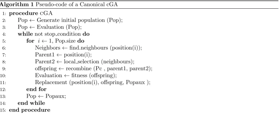
Algorithm 1 shows the pseudo-code of the canon-ical cGA. A cGA starts with a random population;
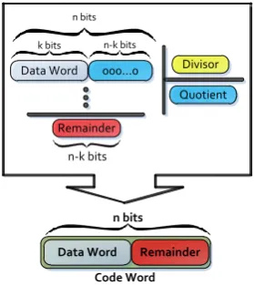
Data Word 000...0 Divisor
Quotient
Remainder
n bits k bits n-k bits
n-k bits
Data Word Remainder n bits
Code Word
Figure 1. Principle of CRC Algorithm.
then, a fitness value is assigned to each individual. After that, the genetic operators such as selection, crossover, mutation, and replacement are applied to each individual and this process continues until the termination condition is reached.
2.3 Cyclic Redundancy Check (CRC)
Many communication systems use the cyclic redun-dancy check (CRC) method to protect important data from errors [29–32]. CRC has been widely used in digital communications because of its performance, simplicity and low usage of software and hardware resources [33–35]. In this study, the error detection ability of CRC is used but this method in some cases can also be used for error correcting applications [33].
In CRC encoding, a data word (M) haskbits; the code word (T) hasnbits. The size of the data word is enhanced by addingn−k, 0s to the right-hand side of the word (e.g., 2n−kM orM is shifted leftn−kbit).
The generatedn-bit result is sent to the generator. The generator uses a predefined and agreed upon divisor of sizen−k+ 1. The generator divides the enhanced data word by the divisor (P). The quotient of the division is discarded; the remainder (R) that is called CRC (n−kbits) is added to the shifted data word (2n−kM) to create the code word (T). In other word
(see Figure 1), the data word (M) is shiftedn−kbits to the left and is divided by a predefined divisor (P) and then is added to the remainder of this division (T = 2n−kM+R). In this case, the addition and the subtraction are the same. We use the XOR operation to do both [36].
Algorithm 1Pseudo-code of a Canonical cGA 1: procedurecGA
2: Pop←Generate initial population (Pop); 3: Pop←Evaluation (Pop);
4: whilenot stop conditiondo
5: for i←1, Pop.sizedo
6: Neighbors←find.neighbours (position(i)); 7: Parent1←position(i);
8: Parent2←local selection (neighbours); 9: offspring←recombine (Pc , parent1, parent2); 10: Evaluation←fitness (offspring);
11: Replacement (position(i), offspring, Popaux ); 12: end for
13: Pop←Popaux; 14: end while
15: end procedure
Otherwise, everything is discarded.
Mathematically, a CRC can be explained as a poly-nomial over Galois Field (GF) and the polypoly-nomial division can be performed by a generator polynomial G(x), which is commonly called a CRC polynomial. Common CRC polynomials can detect the following types of errors:
• All single bit errors
• All double bit errors
• All odd number of errors
• Any burst error for which the burst length is less than the polynomial length
• Most large burst errors [37].
One of the benefits of a cyclic code is that the hard-ware implementation of the encoder and the decoder is done using minimal number of electronic devices. Linear Feedback Shift Register (LFSR) with serial data feed [30] has been used to implement the CRC algorithm (see Figure 2). As all hardware implemen-tations, this method directly performs a division and then the remainder, which is the resulting CRC check-sum, is stored in the registers (D-flip-flop) after each clock cycle. The registers can be read after all of the data words are fed the LFSR. Simplicity and low power consumption are the main advantages and a low speed to produce remainder is the disadvantage of this method. Although the parallel version and fast calculation of the CRC algorithm were designed [38– 40], in this study the serial version of CRC method is utilized with ultimate architecture [36, 37].
3
Proposed Architecture
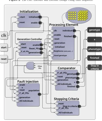
This section discusses the proposed architecture that has the ability to deal with SEUs. In this approach, it is assumed that the SEU attacks the fitness and chromosome registers of the processing element at
the same time. This section also describes the various modules of the Multiple Fault Tolerant cellular Ge-netic Algorithm (MFT-cGA) system that is shown in Figure 3. These MFT-cGA modules are implemented in VHDL and consist of six sub-blocks. Processing Element (PE), Initialization Block, Generation Con-troller, Comparator, Stop in Criteria and Fault Injec-tion are the proposed architecture’s sub-modules.
3.1 Processing Element (PE)
In a cGA, the population is usually arranged in an n-dimensional grid of PEs. The boundary of each PE of the grid is connected to the PE located in the op-posite borders in the same row/column, depending on the case. In fact, all of the PEs has exactly the same number of neighbors. In cGAs, the PEs can only interact with their local neighbors in the reproduc-tive process (line 6 to 11 of Algorithm 1) where the genetic operators (selection, crossover and mutation and so on) are applied. This reproductive process is performed inside the PEs on PE’s individual and its local neighborhood.
In this paper, the two and three-dimensional struc-tures of cGA are implemented. In 3D topology, each PE has six neighborhoods -east, west, horizontal south and north, vertical south and north - but in 2D topol-ogy, each PE has four neighborhoods- North, east, west and south. The main sub-block of the cGA that determines the cell resistance is processing element (PE). The suitable guideline and schemas in this mod-ule can improve the performance of the cellular genetic algorithm in unsafe and threatening, environment.
January 2016, Volume 3, Number 1 (pp. 27–42) 31
D1 D2 D3 D4
P1 P2 D1 P3 D2 D3 D4
د ا د ه ی 4 بی ت ی د ا د ه ی 7 بی ت ی ک د ش د ه
D1 D2 D3 D4
P1 P2 D1 P3 D2 D3 D4
Data Encrypted Data+
+
r(0)
r(1)
+
r(n-k-1) هدادیهملک
d(0)
d(n-k-1) d(1)
+
+ S(0)
S(1) +
S(n-k-1)
d(0) d(n-k-1) d(1)
CRC
coding
و ال د 1 و ال د 2 ان ت خ ا ب ت ص ا د ف ی ان د ی سd0 d1 d2 d3 d4 d5 d6 d7
0 1 2 3 4 5 6 7
d0 d1 d2 d3 d4 d5 d6 d7
0 1 2 3 4 5 6 7
d0 d1 d2 d3 d4 d5 d6 d7
0 1 3 4 5 6 7
d0 d1 d2 d3 d4 d5 d6 d7
0 1 2 3 4 5 6 7
hamming
2 ت ر ک ی ب ی ک ن ق ط ه ا ی ض ع ی ف+
+
r(0)
r(1)
+
r(n-k-1) d(0) d(n-k-1) d(1) Data Word Data WordFigure 2. The CRC Encoder and Decoder Design Using Shift Registers.
clk
start reset phenotype genotype x Stop in criteria finishedInitialization
Initialization
start reset initialized enableProcessing Element
Processing Element
clk enable individual finished reset generation initialized Neighbores(west,east,…) Generation Controller Generation Controller startreset Reset_PEsenable
F_all_PEsgeneration
Fault Injection
Fault Injection
reset F_all_PEs population generation enabl eAll individuals
Stopping Criteria
Stopping Criteria
Stop in criteria F_all_PEs reset
Comparator
Comparator
reset genotype generation All individuals F_all_PEs phenotype x finishedMethod1 CRC coding
English
Good genotype
All individuals Other
PEs
Figure 3. Block Diagram of the Proposed Fault Tolerant Cellular Genetic Algorithm.
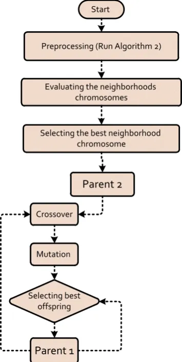
the flowchart of Figure 4.
First, the preprocessing algorithm (Algorithm 2) is done on the neighborhoods’ genotype. Detecting er-ror in Algorithm 2 is done via CRC coding method that is mentioned before. When CRC finds fault in chromosome register, the recovery process is started. This fault can be equivalent to the natural mutation that occurs at chromosome register. The increase in exploration parameter can be observed due to this kind of error. Thus it can disturb the trade-off be-tween exploitation and exploration parameters. Algo-rithm 2 is used to control this kind of fault and the previously mentioned trade-off. In this algorithm, the
Start
Evaluating the neighborhoods chromosomes
Selecting the best neighborhood chromosome
Parent 2
Crossover
Mutation
Selecting best offspring
Preprocessing (Run Algorithm 2)
Parent 1
Figure 4. Proposed Flowchart for Processing Element (PE).
this paper one-point crossover) recombines parent 1 and parent 2 to produce two offspring and the fittest offspring is selected for mutation operation. The mu-tated offspring is evaluated and the fittest individual between mutated offspring and parent 1 is selected to stay in this PE as parent 1 for next generation. Since the fault model in this paper is SEU that occurs at fitness and chromosome register simultaneously, the fitness value of the individual is not used in PEs’ inter-action to prevent the error spread in the population. Consequently, before the start of the PEs operation (after preprocessing unit), fitness values of neighbor-hood genotypes are recalculated in each PE.
3.2 Initialization Block
In Genetic Algorithm, the initial population is usually generated randomly allowing the entire range of pos-sible solutions (the search space). It is also pospos-sible to use some seeding technique in order to speed up the search by starting from good solutions. Similarly, in this paper, the initialization block generates random chromosomes in the first generation for all PEs.
3.3 Generation Controller
Generation controller is a simple counter that controls and determines the generation number for all PEs. This block is triggered when the entire operation of all PEs in the previous generation is finished.
3.4 Comparator
At the end of each generation when all operation of PEs is finished, this sub-module selects the best chromosome of the present population. Therefore, the comparator module shows the fittest solution of each generation.
3.5 Stopping Criteria
Genetic algorithm has three kinds of convergence con-ditions such as the number of generations, the num-ber of uniquely determined schedules and algorithm runtime.
The termination criterion in this module is: “if the average fitness of the population is lower than the threshold value that is set first, the algorithm is terminated”. This threshold value is set based on the global optima point of benchmark functions.
3.6 Fault Injection
To simulate the faulty environment and test our struc-ture in this domain we need a module that injects fault. Therefore, fault injection module, injects SEU faults on PEs chromosome and fitness register simul-taneously, based on defined fault percentage. The fault percentage is set as an input variable. To inject fault, the candidate generations and individuals are randomly selected at the beginning of the proposed structure process.
4
Experimental Study
The previous sections defined the MFT-cGA algorithm and described its sub-modules’ implementation. At the end of the following section, we assess the accuracy and resistance of our predictive model. This section concentrates on proposed fault model, benchmark functions, experimental setup, evaluation metrics and discussion of obtained result.
4.1 Fault Model
January 2016, Volume 3, Number 1 (pp. 27–42) 33
Algorithm 2Pseudo-code of Preprocessing 1: procedurepreprocessing(cGA)
2: Neighbors←Find Neighbors (position (i, j, k)); 3: fori←1 to neighbors countdo
4: if (CRC ( neighbors(i) ) = null vectorthen
5: healthy neighbors(i)=CRC decode (neighbors(i));
6: else
7: C1←CRC decode (neighbors(i));
8: C2←mutation (C1);
9: C3←good genotype;
10: C4←mutation (C3);
11: (C5,C6)←Selection two worst C (C1,C2,C3,C4); 12: (C7,C8)←Selection two best C (C1,C2,C3,C4); 13: (Child1,Child2)←Crossover (C5,C6);
14: healthy neighbors(i)←Selection best individual (Child1,Child2,C7,C8); 15: end if
16: end for
17: returnhealthy neighbors 18: end procedure
one or zero. Furthermore, this error can be found in every generation and on each PEs, randomly. Thus, in algorithmic level, a mismatch happens between chro-mosomes and their finesses due to aforementioned fault model. Therefore, the local selection method selects the faulty individuals (individuals with the maximum/minimum fitness values and incorrect chro-mosome are the fittest) and spreads the incorrect so-lutions in the whole population and guides algorithm to the weak and incorrect solutions. To illustrate the ability of proposed structure to deal with the failures, different amounts of fault are considered in this part, from 0% to 100% of the population size.
4.2 Case Study
There are several benchmarks, which have been widely used in the previous works to test the performance of optimization methods. Four test functions have been used in this study as benchmarks including: Rastrigin, Griwank, Michalewicz and Dropwave Functions.
“Rastrigin” Function
The Rastrigin Function (Equation (1)) is a classic example of non-linear multimodal function [41, 42].
FRas(x) = 10n+ n X
k=1
x2−10 cos(2πxk)
(1)
This function is a challenging problem due to its enormous search space and its large number of local minima. The locations of the local minima are repeat-edly distributed. The complexity of Rastrigin function isO(nlog(n)), where n is the dimension of the prob-lem. The search domain is [−5.12,5.12] in each
vari-−10 −5
0
5
−10 −5 0 5 −20 0 20 40 60 80
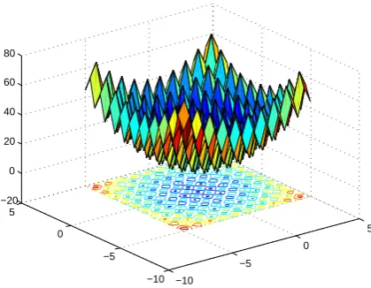
Figure 5. 2D “Rastrigin” Function.
able and the optimum solution of the problem is the vectorv= (0,· · · ,0) withF(v) = 0 (see Figure 5).
“Griewank” Function
The Griewank function [41, 42] is multimodal and non-separable like Rastrigin but the number of its local optima is larger. The function is defined as follows:
FGri(x) =
1 4000
n X
i=1
x2i −
n Y
i=1
cos
x
i
√
i
+ 1 (2) wherenis the number of dimensions of the function. This function has several local optima (Figure 6) within [−600,600]. Its global minimum equalf(x) = 0 and is obtainable forxi= 0,i= 1,· · · , n. Moreover,
−20 −10
0 10
20
−20 −10 0 10 20
−4 −3 −2 −1 0 1
Figure 6. 2D “Griewank” Function.
0 1
2 3
4
0 1 2 3 4 −2 −1.5 −1 −0.5 0
x 10−5
Figure 7. 2D “Michalewicz” Function.
“Michalewicz” Function
The Michalewicz function (Equation (3)) is a multi-modal and separable test function withn! Local op-tima [41, 42].
Fmich(x) =− n X
i=1
sin(xi).
sin
i.x2
i
π
2.m
(3)
In Equation (3), the variables domain is in the [0, π]. In this equation, the m parameter defines the “steepness” of the valleys of function (Larger m leads to more difficult search). In this study, m is set to five. In Figure 7 the two-dimensional plot of this function is shown.
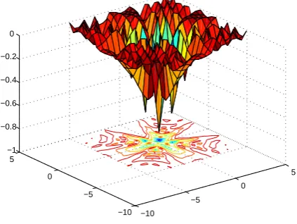
“Drop Wave” Function
Drop wave is a multimodal test function [40, 41]. The test area of this function is in [−5.12,5.12] for all vari-ables. Equation (4) defines the Drop wave’s function:
Fdrop(x1, x2) =−
1 + cos 12√x12+x22
1 2(x1
2+x 22) + 2
(4)
−10 −5
0
5
−10 −5 0 5 −1 −0.8 −0.6 −0.4 −0.2 0
Figure 8. 2D “Drop Wave”
Table 1. Benchmark Functions
Function Search Domain
Global Optima (X,Y)
Stopping Criteria (Threshold)
F Mich [0, π] (2.18328,−0.806919) -0.806
F Ras [−5.12,5.12] (0,0) 0.00005
F Gri [−600,600] (0,0) 0.00005
F Drop [−5.12,5.12] (0,−1) -0.99999
The two-variable version of this function in afore-mentioned search space is shown in Figure 8.
4.3 Simulation Setup
To show the ability of proposed structure in faulty space, 4 test functions are introduced in the previous section. Table 1 reviews the characteristics of the selected test functions. ‘n’ is set to ‘1’ for all test functions.
The last column of the above table shows the con-vergence condition of genetic algorithm in the opti-mization of each test function separately. There are three techniques to determine the convergence of op-timization algorithms. One of them is applying the rules and when the algorithm satisfies that condition, the optimization is stopped. In this study when the av-erage of population fitness in each generation is lower than the threshold value, the algorithm is stopped. This threshold value is shown in the last column of the above table that is selected according to global optima point of each test function.
January 2016, Volume 3, Number 1 (pp. 27–42) 35
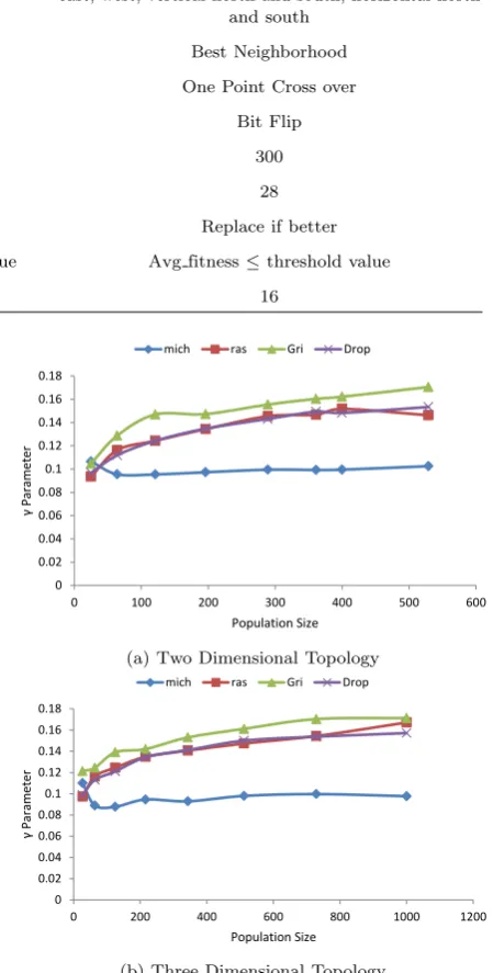
Table 2. Details of Simulation Setup
Parameters MFT-2D-cGA MFT-3D-cGA
Neighborhood east, west, north, south east, west, vertical north and south, horizontal north and south
Parent Selection Best Neighborhood Best Neighborhood
Recombination One Point Cross Over One Point Cross over
Mutation Bit Flip Bit Flip
Max Generation 300 300
Chromosome Length 28 28
Replacement Replace if better Replace if better
Termination Condition Avg fitness≤threshold value Avg fitness≤threshold value
CRC Length 16 16
4.4 Evaluation Metrics
In optimization algorithms, some evaluation metrics are needed to display the performance or superiority of different structures. According to evaluation met-rics that are used in [6, 8, 18-22], two metmet-rics are used in this study. These metrics are efficiency and efficacy. Efficiency and efficacy are measured as the average number of generations and the search success rate of successful out of 100 independent runs respectively. Therefore, the best architecture of optimization algo-rithm for each test function needs to have low effi-ciency and high efficacy leading to lowγ. Equation (5) provides the formula ofγparameter.
γ= ef f iciency
ef f icacy (5)
4.5 Simulation Result
In this part, diagrams are according toγparameter due to its generalization. Therefore,γmetric shows the performance of the algorithm.
In Figure 9, theγis represented vs. population size in two and three-dimensional structures of the popu-lation in proposed architecture. Moreover, these dia-grams are obtained when all of PEs are healthy and no SEU fault is occurred. In these diagrams,γ param-eter is enhanced due to increasing of the population size for each test function. Furthermore, the algorithm converges slower (based on desired convergence condi-tion). In addition, we can infer the performance of the proposed architecture against each test function based on the givenγparameters in the mentioned diagrams.
Figure 10 shows the influence of fault percentage on the proposed architecture. In this figure, the effect of fault percentage in ratio parameter (γ) for three separate population size and two distinct structures are shown (these diagrams are acquired for “Drop
0 0.02 0.04 0.06 0.08 0.1 0.12 0.14 0.16 0.18
0 100 200 300 400 500 600
γ
P
aram
et
er
Population Size
mich ras Gri Drop
(a) Two Dimensional Topology
0 0.02 0.04 0.06 0.08 0.1 0.12 0.14 0.16 0.18
0 200 400 600 800 1000 1200
γ
P
aram
et
er
Population Size mich ras Gri Drop
(b) Three Dimensional Topology
Figure 9.γParameter for 3D and 2D Structure of FT-cGA.
Wave” test function).
0 0.02 0.04 0.06 0.08 0.1 0.12 0.14 0.16
0 10 30 50 70 90 100
γ
P
arame
te
r
Fault Percentage)%(
size=27 size=125 size=343
(a) Two Dimensional Topology
0 0.02 0.04 0.06 0.08 0.1 0.12 0.14 0.16
0 10 30 50 70 90 100
γ
P
arame
te
r
Fault Percentage)%(
size=25 size=121 size=361
(b) Three Dimensional Topology
Figure 10. Fault Percentage and Population Size for 3D and 2D Structure of MFT-cGA in “Drop Wave” Function.
0 0.05 0.1 0.15 0.2 0.25
0 20 40 60 80 100 120
γ
P
aram
et
er
Fault Percentage (%) size=27 size=125 size=343
(a) Canonical cGA
0 0.02 0.04 0.06 0.08 0.1 0.12 0.14 0.16
0 20 40 60 80 100 120
P
arame
te
r
γ
Fault Percentage)%(
size=27 size=125 size=343
(b) Proposed FT-cGA
Figure 11. Fault Percentage and Population Size for 3D Structure of Canonical-FT-cGA and Proposed-FT-cGA in “Rastrigin” Function.
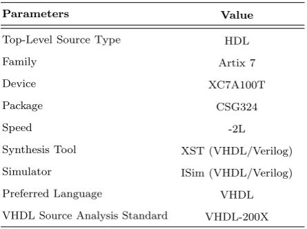
Table 3. ISE Design Properties
Parameters Value
Top-Level Source Type HDL
Family Artix 7
Device XC7A100T
Package CSG324
Speed -2L
Synthesis Tool XST (VHDL/Verilog)
Simulator ISim (VHDL/Verilog)
Preferred Language VHDL
VHDL Source Analysis Standard VHDL-200X
Table 4. MFT-cGA Synthesis Setups
Parameters Name Sets Value
Topology Dimension 3D
Topology Size 2∗2∗2
Chromosome Length 5 bits
CRC Length 4 bits
CRC Polynomial Vector “1101”
Optimization Function Y =x2
Search Area ([x min, x max]) [−5.12,5.12]∈R
Max Number Of Generation 100
Floating Point Size 16 bits
4.6 Synthesis Result
In this part, the result of the hardware implementation of proposed structure (MFT-cGA) in ISE Design Suite 14.2 and the simulation results in MODESIM 6.3 (illustrated in Appendix A) are presented. The ISE
design properties are shown in Table 3.
In Table 3 the Family, Device and the package of FPGA and the language of hardware implementation are shown.
Due to the implementation restrictions, the pro-posed structure of the genetic algorithm was used with decreased parameters. Therefore, based on this fact the simulations parameters that are synthesized in ISE are arranged in Table 4.
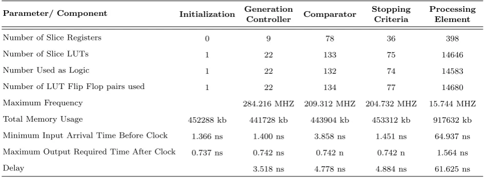
Finally, the detailed synthesis reports of the utiliza-tion of hardware components in FPGA are organized in Table 5.
4.7 Discussion
January 2016, Volume 3, Number 1 (pp. 27–42) 37
Table 5. Component Synthesis Reports
Parameter/ Component Initialization Generation
Controller Comparator
Stopping Criteria
Processing Element
Number of Slice Registers 0 9 78 36 398
Number of Slice LUTs 1 22 133 75 14646
Number Used as Logic 1 22 132 74 14583
Number of LUT Flip Flop pairs used 1 22 134 77 14680
Maximum Frequency 284.216 MHZ 209.312 MHZ 204.732 MHZ 15.744 MHZ
Total Memory Usage 452288 kb 441728 kb 443904 kb 453312 kb 917632 kb
Minimum Input Arrival Time Before Clock 1.366 ns 1.400 ns 3.858 ns 1.451 ns 64.937 ns
Maximum Output Required Time After Clock 0.737 ns 0.742 ns 0.742 n 0.742 n 1.564 ns
Delay 3.518 ns 4.778 ns 4.884 ns 61.625 ns
due to increase in the size of the population. In the structure with a bigger population, more effort is needed to reduce the average number of generation under the defined threshold so the average number of generation for the bigger population is increased.
In the proposed structure, SEU errors on chromo-some register can be detected by CRC method. The best individual of the previous generation and the faulty chromosome are sent to Algorithm 2 to produce a healthy and graceful chromosome which replace the faulty one. Therefore, we can see in Figure 10 that an increase in error percentage reducesγparameter. In other word, the proposed algorithm used the best individual of the previous generation and faulty chro-mosome as a natural mutant individual to enhance the mutation and crossover percentage and improve the trade-off between exploration and exploitation of algorithm. Consequently, the proposed structure has a good performance in the faulty environment.
It can be seen in Figure 11, when the fault percent-age in radiation environment is grown, theγ parame-ter of the proposed structure decreases (the algorithm converges faster) but in canonical version of cGA (Fig-ure 11a) the enhanced fault percentage has a direct effect onγparameter and the canonical version has not a good performance and in some cases it may not be able to reach the optimum solution. In addition, this figure shows that the proposed structure used fault to speed up the convergence time.
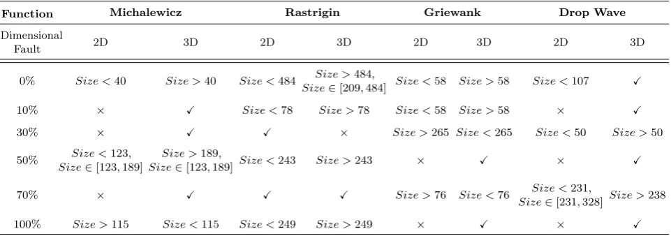
The empirical results illustrate that the algorithm performance significantly depends on the type of benchmark function, population size and fault per-centage. In Table 6 the two and three-dimensional topology of the proposed structure based on men-tioned parameters are compared. According to this table, the three dimensional structure is superior, be-cause good solutions can spread faster in population
due to the large number of neighborhoods.
5
Conclusion
This study proposed a VHDL implementation of a family of MFT-cGA to control failures that occur in individuals’ fitness and chromosome score registers, simultaneously. This approach is based on the canon-ical cGA that is explained in Algorithm 1, and is a complete hardware reconfiguration.
The idea behind this study was to recuperate the im-munity and performance of MFT-cGA by controlling the trade-off between exploration and exploitation (de-tect the fault and recover based Algorithm 2). Also, a comparison is given for MFT-cGA performance when two and three-dimensional topologies of the structure are used to solve the hard optimization functions in different fault percentages. The CRC method is used to detect the fault and to enable the recovery pro-cess. The recovery process helped to control the explo-ration/exploitation trade-off by using the crossover and mutation operators in recovery step (Algorithm 2). On the other hand, when fault occurrence enhances the exploration parameter, the recovery tools fix the exploration/exploitation trade-off. Furthermore, to prevent the fault spread effect in a population due to fitness failure, the fitness values of neighboring PEs were not used.
Table 6. Comparison of Two Structures of FT-cGAs in Ratio Parameter for All Test Functions, Different Sizes of Population and Fault Percentages
Function Michalewicz Rastrigin Griewank Drop Wave
Dimensional
Fault 2D 3D 2D 3D 2D 3D 2D 3D
0% Size <40 Size >40 Size <484 Size >484,
Size∈[209,484] Size <58 Size >58 Size <107 X
10% × X Size <78 Size >78 Size <58 Size >58 × X
30% × X X × Size >265 Size <265 Size <50 Size >50
50% Size <123, Size∈[123,189]
Size >189,
Size∈[123,189] Size <243 Size >243 × X × X
70% × X X X Size >76 Size <76 Size <231,
Size∈[231,328]Size >238
100% Size >115 Size <115 Size <249 Size >249 × X × X
×: The selected dimension is not suitable for optimization.
X: The selected dimension is suitable for optimization in all domains.
offers considerable improvements inγparameter and reliability of the algorithms, especially for cases with a high ratio of faults.
In experimental results, we noted that the proposed architecture with initiative recovery tools and changes in PEs connectivity, showed good performance. In ad-dition, using the well-organized recovery policy, the algorithm can use the previous generation fittest an-swers to recover faulty individual; therefore, the algo-rithm does not have much time overhead. Thus, this structure is suitable for real time application. Finally, Table 6 illustrates which topology of proposed MFT-cGA (2D or 3D) is better in a variety of conditions (population size, fault percentage occurred for opti-mization of all test functions).
References
[1] Enrique Alba. Parallel Metaheuristics: A New Class of Algorithms. Wiley, 2005. ISBN
978-0-471-67806-9.
[2] Christian Blum and Andrea Roli. Metaheuris-tics in combinatorial optimization: Overview and conceptual comparison. ACM Comput. Surv., 35 (3):268–308, September 2003. ISSN 0360-0300. doi: 10.1145/937503.937505. URLhttp://doi.
acm.org/10.1145/937503.937505.
[3] E. Alba and M. Tomassini. Parallelism and evo-lutionary algorithms. IEEE Transactions on Evolutionary Computation, 6(5):443–462, Oct 2002. ISSN 1089-778X. doi: 10.1109/TEVC. 2002.800880.
[4] Thomas B¨ack. Evolutionary algorithms in theory and practice: evolution strategies, evolutionary programming, genetic algorithms. Oxford univer-sity press, 1996.
[5] Thomas B¨ack, David B. Fogel, and Zbigniew Michalewicz, editors. Handbook of Evolution-ary Computation. Oxford university press, 1997. ISBN 0750303921.
[6] Alicia Morales Reyes.Fault tolerant and dynamic evolutionary optimization engines. PhD thesis, 2011.
[7] M. Giacobini, M. Tomassini, A. G. B. Tetta-manzi, and E. Alba. Selection intensity in cellu-lar evolutionary algorithms for regucellu-lar lattices. IEEE Transactions on Evolutionary Computa-tion, 9(5):489–505, Oct 2005. ISSN 1089-778X. doi: 10.1109/TEVC.2005.850298.
[8] A. Al-Naqi, A. T. Erdogan, and T. Arslan. Fault tolerant three-dimensional cellular genetic algo-rithms with adaptive migration schemes. In Adaptive Hardware and Systems (AHS), 2011 NASA/ESA Conference on, pages 352–359, June 2011. doi: 10.1109/AHS.2011.5963958.
[9] E. Alba and B. Dorronsoro. The explo-ration/exploitation tradeoff in dynamic cellu-lar genetic algorithms. IEEE Transactions on Evolutionary Computation, 9(2):126–142, April 2005. ISSN 1089-778X. doi: 10.1109/TEVC. 2005.843751.
[10] A. Al-Naqi, A. T. Erdogan, T. Arslan, and Y. Mathieu. Balancing exploration and exploita-tion in an adaptive three-dimensional cellular ge-netic algorithm via a probabilistic selection oper-ator. InAdaptive Hardware and Systems (AHS), 2010 NASA/ESA Conference on, pages 258–264, June 2010. doi: 10.1109/AHS.2010.5546248. [11] Enrique Alba and Jos´e Ma Troya. Cellular
January 2016, Volume 3, Number 1 (pp. 27–42) 39
Berlin, Heidelberg, 2000. ISBN 978-3-540-45356-7. doi: 10.1007/3-540-45356-3 3. URL http:
//dx.doi.org/10.1007/3-540-45356-3_3.
[12] Fernanda Gusm˜ao de Lima, Exame de Quali-fica¸c˜ao, and Ricardo Augusto da Luz Reis. Sin-gle event upset mitigation techniques for pro-grammable devices. Porto Alegre, 14, 2000. [13] R. Velazco, R. Ecoffet, and F. Faure. How to
characterize the problem of seu in processors representative errors observed on flight. In11th IEEE International On-Line Testing Symposium, pages 303–308, July 2005. doi: 10.1109/IOLTS. 2005.32.
[14] J. F. Ziegler and W. A. Lanford. Effect of cosmic rays on computer memories. Science, 206(4420): 776–788, 1979. ISSN 0036-8075. doi: 10.1126/ science.206.4420.776. URL http://science.
sciencemag.org/content/206/4420/776.
[15] Jiangning Xu, T. Arslan, Qing Wang, and De-jun Wan. An ehw architecture for real-time gps attitude determination based on parallel genetic algorithm. InEvolvable Hardware, 2002. Proceed-ings. NASA/DoD Conference on, pages 133–141, 2002. doi: 10.1109/EH.2002.1029877.
[16] E. F. Stefatos and T. Arslan. High-performance adaptive gps attitude determination vlsi architec-ture. InSignal Processing Systems, 2004. SIPS 2004. IEEE Workshop on, pages 233–238, Oct 2004. doi: 10.1109/SIPS.2004.1363055.
[17] Cesar Ortega-Sanchez, Daniel Mange, Steve Smith, and Andy Tyrrell. Embryonics: A bio-inspired cellular architecture with fault-tolerant properties. Genetic Programming and Evolv-able Machines, 1(3):187–215, 2000. ISSN 1573-7632. doi: 10.1023/A:1010080629099. URLhttp:
//dx.doi.org/10.1023/A:1010080629099.
[18] A. Morales-Reyes, E. F. Stefatos, A. T. Erdogan, and T. Arslan. Fault tolerant cellular genetic al-gorithm. In2008 IEEE Congress on Evolutionary Computation (IEEE World Congress on Com-putational Intelligence), pages 2671–2677, June 2008. doi: 10.1109/CEC.2008.4631157.
[19] A. Morales-Reyes, E. F. Stefatos, A. T. Erdogan, and T. Arslan. Towards fault-tolerant systems based on adaptive cellular genetic algorithms. In Adaptive Hardware and Systems, 2008. AHS ’08. NASA/ESA Conference on, pages 398–405, June 2008. doi: 10.1109/AHS.2008.44.
[20] A. Morales-Reyes, N. Haridas, A. T. Erdogan, and T. Arslan. Fault tolerant and adaptive gps attitude determination system. In 2009 IEEE Aerospace conference, pages 1–8, March 2009. doi: 10.1109/AERO.2009.4839532.
[21] A. Al-Naqi, A. T. Erdogan, and T. Arslan. Fault tolerance through automatic cell isolation using three-dimensional cellular genetic algorithms. In
IEEE Congress on Evolutionary Computation, pages 1–8, July 2010. doi: 10.1109/CEC.2010. 5586209.
[22] Asmaa Al-Naqi, Ahmet T. Erdogan, and Tughrul Arslan. Dynamic fault-tolerant three-dimensional cellular genetic algorithms. Jour-nal of Parallel and Distributed Computing, 73(2):122 – 136, 2013. ISSN 0743-7315. doi: http://dx.doi.org/10.1016/j.jpdc.2012.09.
011. URL http://www.sciencedirect.com/
science/article/pii/S0743731512002262.
[23] P Ashooriyan and Y Baleghi. A Compara-tive Study of VHDL Implementation of FT-2D-CGA and FT-3D-CGA on Different Bench-marks (Research Note). International Journal of Engineering-Transactions C: Aspects, 28(9): 1276–1285, 2015.
[24] E Normand. Single event upset at ground level. IEEE Transactions on Nuclear Science, 43(6): 2742–2750, 1996.
[25] Fernanda Gusm˜ao de Lima. Single event upset mitigation techniques for programmable devices. Master’s thesis, Porto Alegre, Brasil, 2000. [26] J. A. Zoutendyk, L. D. Edmonds, and L. S.
Smith. Characterization of multiple-bit errors from single-ion tracks in integrated circuits.IEEE Transactions on Nuclear Science, 36(6):2267–
2274, Dec 1989. ISSN 0018-9499. doi: 10.1109/ 23.45434.
[27] R´emi Gaillard. pages 27–54. Springer US, Boston, MA, 2011. ISBN 978-1-4419-6993-4. doi: 10.1007/978-1-4419-6993-4 2. URLhttp://dx.
doi.org/10.1007/978-1-4419-6993-4_2.
[28] Enrique Alba and Bernab´e Dorronsoro. Cellu-lar genetic algorithms, volume 42. Springer US, 2009. ISBN 978-0-387-77609-5. doi: 10.1007/ 978-0-387-77610-1.
[29] Sunil S Gaitonde and Tenkasi V Ramabadran. A tutorial on crc computations. IEEE Micro, 8(4): 62–75, 1988.
[30] William Wesley Peterson and Daniel T Brown. Cyclic codes for error detection. Proceedings of the IRE, 49(1):228–235, 1961.
[31] William Stallings. Data and computer communi-cations. Pearson/Prentice Hall, 2007.
[32] N. R. Saxena and E. J. McCluskey. Analysis of checksums, extended-precision checksums, and cyclic redundancy checks. IEEE Transactions on Computers, 39(7):969–975, Jul 1990. ISSN 0018-9340. doi: 10.1109/12.55701.
[34] C. A. Johnston and H. J. Chao. The ATM layer chip: an ASIC for B-ISDN applications. IEEE Journal on Selected Areas in Communications, 9(5):741–750, Jun 1991. ISSN 0733-8716. doi: 10.1109/49.87644.
[35] O. O. Khalifa, M. D. Rafiqul Islam, and S. Khan. Cyclic redundancy encoder for error detection in communication channels. InRF and Microwave Conference, 2004. RFM 2004. Proceedings, pages 224–226, Oct 2004. doi: 10.1109/RFM.2004. 1411112.
[36] A Behrouz Forouzan. Data Communications & Networking. McGraw-Hill Education, 4 edition, 2006. ISBN 9780073250328.
[37] Ulf Nordqvist, Tomas Henriksson, and Dake Liu. Crc generation for protocol processing. In pro-ceedings of NORCHIP, pages 288–293, 2000. [38] J. R. Engdahl and D. Chung. Fast parallel crc
implementation in software. InControl, Automa-tion and Systems (ICCAS), 2014 14th Interna-tional Conference on, pages 546–550, Oct 2014. doi: 10.1109/ICCAS.2014.6987839.
[39] F. Monteiro, A. Dandache, A. M’sir, and B. Lep-ley. A fast crc implementation on fpga using a pipelined architecture for the polynomial divi-sion. InElectronics, Circuits and Systems, 2001. ICECS 2001. The 8th IEEE International Confer-ence on, volume 3, pages 1231–1234 vol.3, 2001. doi: 10.1109/ICECS.2001.957437.
[40] G. Campobello, G. Patane, and M. Russo. Par-allel crc realization. IEEE Transactions on Com-puters, 52(10):1312–1319, Oct 2003. ISSN 0018-9340. doi: 10.1109/TC.2003.1234528.
[41] Marcin Molga and Czes law Smutnicki. Test functions for optimization needs. 2005. Available:http://www.zsd.ict.pwr.wroc.pl/
files/docs/functions.pdf.
[42] Hartmut Pohlheim. Examples of objective func-tions. 2007. Available: http://www.geatbx.
com/download/GEATbx_ObjFunExpl_v37.pdf.
A
Simulation Waveform Results in
MODELSIM
In this part, the Timing Simulation waveform of the implementation of Multiple Fault Tolerant Cellular Genetic Algorithm in MODELSIM is shown in two figures. In Figure A.1 the two-dimensional structure of MFT-cGA in 100th run of Rastringin function in size 3*3 of cellular shapes in fault percentage of 0% to 50% is illustrated. Figure A.2 is similar to group (a) but the fault percentage is different. In Figure A.2 the fault percentage is between 70% and 90%.
Peyman Ashoorianwas born in 1990 in
Tonekabon (Iran). He received his B.Sc. de-gree in Hardware Computer engineering in 2004 from Babol Noshirvani University of Technology, Babol, Iran. He then worked toward the M.Sc. degree in the same uni-versity in Electronic Engineering and grad-uated in 2014. His research interests in-clude the field of evolvable and adaptive hardware and fault tolerant system design.
January 2016, Volume 3, Number 1 (pp. 27–42) 41