Iranian Journal of Electrical and Electronic Engineering, Vol. 14, No. 4, December 2018 353
Fuzzy-Genetic Algorithm-Based Direct Power Control
Strategy for DFIG
E. Heydari*(C.A.), M. Rafiee* and M. Pichan**
Abstract: Among a multitude of diverse control methods proposed for doubly fed induction generator (DFIG) based-wind energy conversion systems, direct power control (DPC) method has demonstrated superior dynamic performance and robustness in presence of disturbances. However, DPC is not a flawless method and shortcomings like necessity for high sampling frequency, high-speed sensors and less noise-affected sampling circuit need to be mitigated by utilizing fuzzy controllers. Parameter setting in a fuzzy controller plays a vital role, especially under non-ideal grid conditions. In this paper, a fuzzy-genetic algorithm-based direct power control (FGA-DPC) method is proposed for DFIG, while, the parameters of the fuzzy controller are optimized by genetic algorithm. The objective of the optimization is to minimize the stator active and reactive power errors to increase the precision of reference tracking. The objectives of the controller are also optimizing active power absorption based on the zone of operation and adjustment of reactive power according to grid requirements. The proposed method improves the overall precision and speed of transient response as well as significantly reducing power oscillations under non-ideal grid conditions. Finally, to demonstrate the effectiveness of the proposed method, extensive simulations are performed in Matlab/Simulink under different conditions.
Keywords: Wind Energy Conversion System, DFIG, Direct Power Control, FGA-DPC.
Nomenclature1
φs, φr Stator and rotor flux vectors Is,Ir Stator and rotor current vectors Vs,Vr Stator and rotor voltage vectors Ls,Lr Stator and rotor self-inductances
Lm Mutual inductance
Rs,Rr Stator and rotor resistances
Subscripts
s, r Stator, rotor
d, q Synchronous d-q axis
Superscript
s Synchronous reference frame
Iranian Journal of Electrical and Electronic Engineering, 2018. Paper first received 01 November 2017 and accepted 24 May 2018. * The authors are with the Department of Electrical Engineering, Shahid Beheshti University, Tehran, Iran.
E-mails: [email protected] and [email protected].
** The author is with the Department of Electrical Engineering, Amirkabir University of Technology, Tehran, Iran.
E-mail: [email protected]. Corresponding Author: E. Heydari.
1 Introduction
N the past decades, with increasing use of renewable energy resources, it has been reported that the cumulative wind capacity installed worldwide at the end of 2021 would reach over 800 GW [1]. Among the generators used in variable speed wind turbines, doubly fed induction generators (DFIG) have been considered to a greater extent [2-5]. So, various control methods have been proposed for DFIGs. Among these methods, direct power control (DPC) offers many advantages include: fast dynamic response, simplicity in calculations, and robustness against machine parameter mismatches [6-9]. The DPC method presented in [10], imposes some drawbacks such as variable switching frequencies. Although several methods have been proposed with fixed switching frequency [11, 12], these methods require high sampling frequency to show good steady state and transient performance. High sampling frequency means high-speed sensors and sampling circuits which must be enough robust against external noise, which leads to increased cost of the system. So in [13, 14], direct power control method based on fuzzy
I
Iranian Journal of Electrical and Electronic Engineering, Vol. 14, No. 4, December 2018 354 controller has been proposed. This controller provides
advantages such as reduced dependence on accurate model of the system, robustness against change in the machine parameters, and robustness against noise. In [13], DPC is presented based on discrete space vector modulation (DSVM), and a fuzzy controller is used to reduce power ripples. The switching table used in this method makes it necessary for reducing the power ripples to have high switching frequency and many vector definitions. In [14], the fuzzy-based DPC is used to control the active and reactive powers. However, this method restricts its control on fixed power gained from the turbine. Besides, it does not consider the turbine dynamics connected to the DFIG and its analytical information. On the other hand, due to the nonlinearity and complexity of the system, it is not easy to find the optimal scale factors for the controller, which was not addressed in this reference.
Since finding the optimal fuzzy control coefficients plays an important role in the accuracy of the response and lower power errors, optimization algorithms can be used for the automatic adjustment of these coefficients. Among these algorithms, genetic algorithm (GA) because of its advantages such as wide solution space, ease of discovering global optimum, resistance against becoming trapped in local optimum and ease of implementation is highly attractive and usable [15-17]. In this paper, a new direct power control strategy for DFIG in wind energy conversion systems is proposed. The proposed strategy is fuzzy-genetic algorithm-based direct power control (FGA-DPC). The aim of optimizing the scale factors by the genetic algorithm is to minimize the stator active and reactive power error in reference tracking. Also, by the appropriate setting of reference power, the power absorbed from the turbine is adjusted with respect to the performance zone. In other words, the purpose of the controller is to adjust reactive power according to grid requirements and optimize the active power with the minimum error.
2 System Description
The mechanical power of the wind turbine (Pt) is a
function of the available power in the wind (Pv=½ πρR2v3). The mechanical power of the wind
turbine can be obtained based on (1):
1 2 3
, ,
2
t v p p p p
P P C R v C (1)
where v is the wind speed, ρ is the air density, and R is the blade length, respectively. On the other hand and after some calculations, the mechanical torque of the turbine can be obtained as follow [18].
3 2 12
t t
t
rm gb
C R v
P T
K
(2)
where Ct (λ) is the torque coefficient of the turbine.
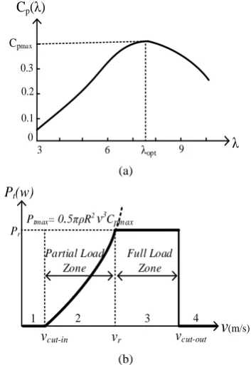
When the pitch angle βp is constant, Cp is a nonlinear
function of λ and has a unique maximum value for
λ = λopt that is shown in Fig. 1(a). The relationship
between wind speed and produced power by the turbine is shown in Fig. 1(b). The turbine performance is useful just in two regions; in zone 2 (partial load zone), in which the target would be to absorb maximum power from the wind. In zone 3 (full load zone), in which it is necessary to limit the absorbing power to the rated value by controlling pitch angle of the blades or electrical circuit.
2.1 Dynamic Model of the DFIG
The dynamic behavior of the DFIG can be explained based on the five differential equations [14].
s
s s s s
s s s s s
d
V R I j
dt
(3)
s
s s r s
r r r s m r
d
V R I j
dt
(4)
s s s
s L Is s L Im r
(5)
s s s
r L Im s L Ir r
(6)
3 2
rm
e ds qs qs ds t
d
T p I I T J
dt
(7)
where ωs and ωm are stator and mechanical angular
frequencies, respectively. In addition, Te denotes the
electrical torque of the generator, Tt is the torque
produced by the wind turbine, J is the inertia of the whole rotating parts, and p is the number of pole pairs.
0.1 0.2 0.3
Cpmax
3 6 λopt 9 λ
0
Cp(λ)
(a)
(b)
Fig. 1 Wind energy conversion system: a) Curve of Cp based
on λ, ( 20/ )
( ) 9.5946(12 / 1) , ( 0)
p p
C e and
b) Zones of operation for a wind turbine.
vcut-in Pt(w)
v
(m/s)vr vcut-out
Pr
1 2 3 4
Partial Load Zone
Full Load Zone
Ptmax= 0.5πρR2v3Cpmax
Iranian Journal of Electrical and Electronic Engineering, Vol. 14, No. 4, December 2018 355 3 Controller
3.1 Active and Reactive Power Control
Using (5) and (6), the stator current in the synchronous reference frame is obtained as follows:
2
2
;
s s s s
s r s m r s m r
s
s s r
s r m s r m
s r
L L L
I
L L L
L L L
L L L
L L (8)
Under ideal grid voltages, amplitude and rotating speed of the stator flux are fixed, so dφss/dt = 0. Therefore,
neglecting the stator resistance, the stator voltage equation can be simplified as (9).
s s
s ds qs s s
V V jV j (9)
By alignment of d-axis of synchronous reference frame and the stator flux vector, active and reactive power can be expressed as follow:
s qs qr
P k V (10)
r qs
s qs dr
m s
L V
Q k V
L
(11)
where kσ = 3/2Lm/(σLsLr). The Eq. (10) and (11) imply
that the injected active and reactive power to the grid can be controlled by φqr and φdr, respectively. Now, the
rotor flux derivation at each small sampling time (Ts)
can be written as follows:
1 s s s r r r ss s s
r r r s m r
k k
d
dt T
V R I k j k
(12)
After decomposing (12) and regardless of the rotor resistance, d and q components of the rotor flux in the (k+1) sample instant are obtained and given in (13) and (14).
1
dr dr s dr
s s m qr
k k T V k
T k
(13)
1
qr qr s qr
s s m dr
k k T V k
T k
(14)
In a dead beat theory with two sample delays, the target is to calculate the switching signal at instant k+1 based on the current values (instant k). As a result, all of the values at instant k+1 are considered the reference values, so:
1
ref
P k P k (15)
1
ref
Q k Q k (16)
Again, by considering (15) and (16) and substituting (13) and (14) in (10) and (11), the rotor reference voltage values in the synchronous reference frame are obtained as follows [14]:
1 s
qr s m dr
s qs
P
V k
T k V k
(17)
1 s
dr s m qr
s qs
Q V
T k V k
(18)
Therefore, the stator active and reactive power control occurs through q and d components of the rotor voltage (Vqr and Vdr), respectively.
To generate the reference voltages of the rotor side converter, reference values of the stator active power at the speed higher and lower speeds than the rated speed are needed. When the machine is operated in the maximum power absorption (Cp = Cpmax, λ = λopt), the
torque can be stated in proportion to the square of the rotor speed as follows:
5
2 2
3 3 2
pmax
opt rm o rm
gb opt R C T k k
(19)
where
5
3 3 .
2 pmax o gb opt R C k k
On the other hand, when the
wind speed is high and power production is limited to the rated value, the torque equation can be obtained as (20). r r rm P T
(20)
where Pr is rated power. Therefore, the value of Psref is
proportional to: ref s sref T P p
(21)
where Tref is the amount of reference torque which is
dependent on the performance zone presented in (19) and (20). Finally, the amount of Qsref is considered
according to the needs of the grid.
3.2 Design of FGA-DPC
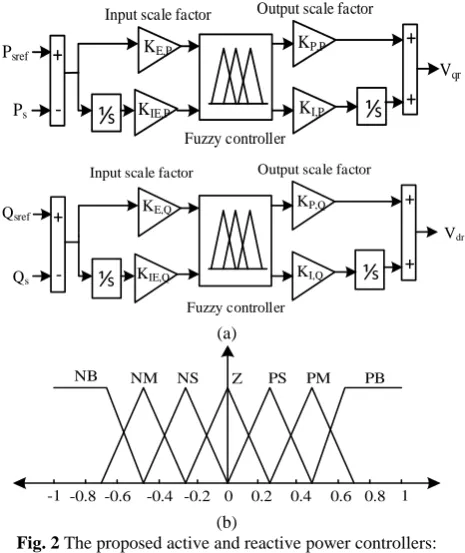
In this study, in order to control active and reactive powers, two independent fuzzy controllers are used. Active power controller gets the stator active power error (ep) and its integration (∫ep) as input and produces
q-axis rotor voltage (Vqr) as output. On the other hand,
reactive power controller inputs are stator reactive power error (eq) and its integration (∫eq) and its output is d-axis rotor voltage (Vdr). The structures of the proposed
controllers are shown in Fig. 2(a).
Each input and output variable in the fuzzy plane is
Iranian Journal of Electrical and Electronic Engineering, Vol. 14, No. 4, December 2018 356 introduced with seven membership functions. These
membership functions are shown in Fig. 2(b) and fuzzy rules are shown in Table 1.
An example of these rules is considered below:
If ep eq is and , then is .x is y w
In the proposed controller, Mamdany inference engine,
min–max fuzzy communication system, and
defuzzification method of centroid are used [18]. In the structures of the proposed controllers shown in Fig. 2(a), KE,P, KIE,P, KE,Q, and KIE,Q are input scale
factors of the active and reactive power controllers, respectively. Besides, KP,P, KI,P, KP,Q, and KI,Q are
output scale factors of the controllers. These coefficients are adjusted by genetic algorithm because of its advantages.
3.3. Genetic Algorithm
Genetic algorithm, instead of working on a solution and optimizing it in the next iteration, works on the set of solutions simultaneously and gradually converges toward an optimal point. Thus, the probability of falling into the local minimum trap is too low.
The steps of the GA algorithm implementation for the proposed method are summarized as follows:
1. Start: At this stage, the initial population is randomly generated according to the production method given in (22).
Initial population Khi Klo KnormKlo (22)
whereKhi is the largest number in a range of variable, Klo is the smallest number in a range of variable, and Knorm is the normalized value of variable. The initial
population size is considered equal to 20.
2. Fitness: The merit of each chromosome is evaluated based on the objective function which is defined as Minimize Jtotal:
1 2
total sref s sref s
J
W P P W Q Q dt (23)where W1 and W2 are the weighting coefficients.
3. Selection: Two parents are selected from a population based on their fitness (more fitness, more chance of being selected).
4. Crossover: At this stage, the crossover operators act on the chromosomes of the parents. Each pair of parents is considered below:
1 2 1
var
m m m mN
Parent P P PP
(24) 1 2
2 .
var
d d d dN
Parent P P PP
* var
roundup random N
where m and d are the indexes of the mother and father chromosomes. Also, Nvar is the number of variables
which equal to 8. The chromosomes selected in (24) are combined to produce children by single-point crossing. Finding the random point to single-point crossing is shown in (25) [19].
1
new m m d
P P PP
(25)
2
new d m d
P P PP
where β is a random value within the range (1,0). The final stage in crossing is completing children as shown in (26):
1 2 1
1 2 2
1
2 .
var
var
m m new dN
d d new mN
offspring P P P P
offspring P P P P
(26)
5. Mutation: At this stage, mutation process with probability 0.2 acts on the chromosomes of crossover and, by changing the bits of chromosomes, creates a way to enter new information.
Ps +
+ Vqr
KE,P
KIE,P
KP,P
KI,P
+
-Psref
Fuzzy controller
Input scale factor Output scale factor
⅟
s⅟
sQs
+ +
Vdr
KE,Q
KIE,Q
KP,Q
KI,Q
+
-Qsref
Fuzzy controller
Input scale factor Output scale factor
⅟
s⅟
s(a)
-1 -0.8 -0.6 -0.4 -0.2 0 0.2 0.4 0.6 0.8 1 Z PS PM PB NS
NM NB
(b)
Fig. 2 The proposed active and reactive power controllers: a) Controllers block diagram and
b) Normalized membership functions.
Table 1 Rule base of fuzzy controller. Δe
e NB NM NS Z PS PM PB
Z PS PM PB PB PB PB PB
NS Z PS PM PB PB PB PM
NM NS Z PS PM PB PB PS
NB NM NM Z PM PM PB Z
NB NB NM NS Z PS PM NS
NB NB NB NM NS Z PS NM
NB NB NB NB NM NS Z NB
Iranian Journal of Electrical and Electronic Engineering, Vol. 14, No. 4, December 2018 357 6. Accepting: Then, the children are placed in a new
population.
7. Replace: At this stage, the new population is selected to enter the next stage algorithm, which is done by comparing the fitness of chromosomes.
8. Test: At this stage, all the new population will be assessed. If the conditions for termination of the algorithm are provided, the algorithm ends; otherwise, the population as initial population will be used for the next stage.
In the optimization process via GA, the goal is to minimize J (fitness function) in order to minimize the stator active and reactive power error to precisely track the reference values. For this purpose, optimization variables are considered as KP,P, KI,P , KIE,P and KE,P for
active power controller and KP,Q, KI,Q, KE,Q, and KIE,Q
for reactive power controller. So there are 8 optimization variables in genetic algorithm. The detailed block diagram for fuzzy controller optimized by genetic algorithm is shown in Fig. 3.
Actually, the fitness function is obtained from simulated system in Simulink and it has been called using “sim” command in genetic algorithm to capture the results from Simulink file.
4 Simulations Results
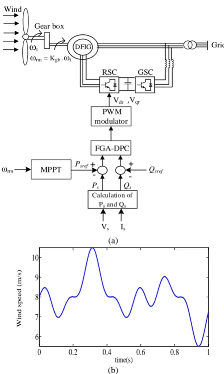
In order to evaluate the performance of the proposed control system under various conditions, extended simulations in Matlab/Simulink are carried out. The scheme of the simulated system is shown in Fig. 4(a). The parameters of the simulated system are given in Table 2. A wind speed profile is considered as shown in Fig. 4(b), which guarantees the operation of the system in both acceptable zones.
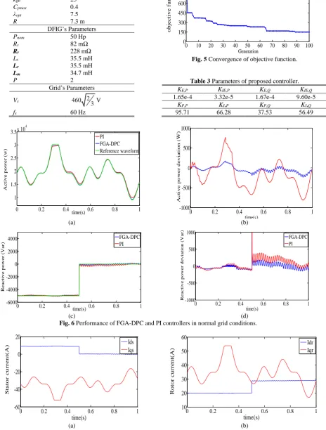
In order to provide a better evaluation and show the superior performance of the proposed FGA-DPC controller, the results of implementing the proposed controller are compared to those of a PI controller under various condition that gains of PI controller is also set by genetic algorithm [20]. The convergence of the objective function in terms of the number of generations is presented in Fig. 5, demonstrating that, at the end of the algorithm, the objective function reaches its optimal value. The scale factors of proposed controller are given in Table 3.
In order to provide a better evaluation and show the superior performance of the proposed FGA-DPC controller, the results of implementing the proposed controller are compared to those of a PI controller under various condition that gains of PI controller is also set by genetic algorithm [20]. The convergence of the objective function in terms of the number of generations is presented in Fig. 5, demonstrating that, at the end of the algorithm, the objective function reaches its optimal value. The scale factors of proposed controller are given in Table 3.
4.1 Operation under Ideal Grid Condition
The first study is related to evaluating the performance of the control system in normal grid conditions. In this case, the reference active power is prepared according to (21) in order to achieve the control purposes. The results for active and reactive powers are shown in Fig. 6. Also, stator and rotor currents are shown in Fig. 7. Accordingly, the results indicate precise and appropriate reference tracking of the proposed controller with lower errors, which leads to improved power absorption process from wind turbine and also supplies the required reactive power.
DFIG
fitness:
min(Eq.23) Genetic Algorithm
Proposed Controller (Fig.2) KP,P KI,P KP,Q KI,Q
KIE,Q
KE,PKIE,PKE,Q
Ps
Psref
Qs
Qsref
vqr
vdr
Fig. 3 The detailed block diagram of fuzzy controller optimized by genetic algorithm.
Grid Gear box
Wind
ωt ωrm= Kgb .ωt
DFIG
FGA-DPC
Calculation of Ps and Qs
Vs Is
+
-Vdr ,Vqr
+
-Psref
Qsref
Ps Qs
PWM modulator
RSC GSC
MPPT ωrm
(a)
0 0.2 0.4 0.6 0.8 1
6 7 8 9 10
time(s)
W
ind s
pe
e
d (
m
/s
)
(b)
Fig. 4 The simulated system by the proposed controller: a) Scheme of the simulated system and b) Wind speed profile.
Iranian Journal of Electrical and Electronic Engineering, Vol. 14, No. 4, December 2018 358 Table 2 Parameters of the simulated system.
WT’s Parameters
J 3.662 kg.m2
kgb 25
Cpmax 0.4
λopt 7.5
R 7.3 m
DFIG’s Parameters
Pnom 50 Hp
Rs 82 mΩ
Rr 228 mΩ
Ls 35.5 mH
Lr 35.5 mH
Lm 34.7 mH
P 2
Grid’s Parameters
Vs 460 2
3V
fs 60 Hz
0 10 20 30 40 50 60 70 80 90 100
0 150 300 450 600 750 900 1050
o
b
jectiv
e
fu
n
ctio
n
Generation
Fig. 5 Convergence of objective function.
Table 3 Parameters of proposed controller.
KE,P KIE,P KE,Q KIE,Q
1.65e-4 3.32e-5 1.67e-4 9.60e-5
KP,P KI,P KP,Q KI,Q
95.71 66.28 37.53 56.49
0 0.2 0.4 0.6 0.8 1
1 1.5 2 2.5 3 3.5x 10
4
time(s)
A
c
ti
ve
po
w
e
r
(w
)
PI FGA-DPC Reference waveform
0 0.2 0.4 0.6 0.8 1
-1000 -500 0 500 1000
time(s)
A
c
ti
ve
po
w
e
r
d
e
v
ia
ti
on
(
W
)
(a) (b)
0 0.2 0.4 0.6 0.8 1
-6000 -4000 -2000 0 2000 4000
time(s)
R
e
a
c
ti
v
e
pow
e
r
(V
a
r)
FGA-DPC PI
0 0.2 0.4 0.6 0.8 1 -1000
-500 0 500 1000
time(s)
R
e
a
c
ti
v
e
pow
e
r
de
vi
a
ti
on
(
V
a
r)
FGA-DPC PI
(c) (d)
Fig. 6 Performance of FGA-DPC and PI controllers in normal grid conditions.
0 0.2 0.4 0.6 0.8 1
-60 -40 -20 0 20
time(s)
St
ato
r
cu
r
r
en
t(
A)
Ids Iqs
0 0.2 0.4 0.6 0.8 1
10 20 30 40 50 60
time(s)
R
o
to
r
cu
rr
en
t(
A)
Idr Iqr
(a) (b)
Fig. 7 Stator and rotor currents in normal grid conditions.
Iranian Journal of Electrical and Electronic Engineering, Vol. 14, No. 4, December 2018 359 4.2 Operation under Non-Ideal Grid Voltage
4.2.1 Operation under Grid Voltage Dip
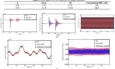
In this study, the grid voltage dip condition is considered on the operation of the DFIG. This fault is a 20% voltage dip in 200 ms. For gaining a better assessment of the transient performance, the wind and reactive powers are considered to be constant and the results are shown in Fig. 8(a). The results reveal that the use of the proposed controller not only is effective in fast oscillation damping of the active and reactive power, but also makes the system stable earlier which improves the whole stability of the system. It is worth to be mentioned that the THD value of the grid current is 1.3% under this condition for the proposed method which verify the effectiveness of the proposed method.
4.2.2 Operation under Imbalanced Grid Voltages
In order to study the behavior of the controller under the condition of imbalanced grid voltage, three-phase voltages of the grid with regard to the sequence of positive and negative sequence components are considered in (27). The performance of the controllers in this mode for tracking the stator powers considering
k = 0.01 is shown in Fig. 8(b).
cos cos
2 2
cos cos
3 3
2 2
cos cos
3 3
ag m s m s
bg m s m s
cg m s s
v V t kV t
v V t kV t
v V t k t
(27)
The results show a significant reduction in power oscillations by using the fuzzy genetic controller in comparison to the case using PI controller. Also, for better comparison, the value of power ripple is obtained from (28) and the results for the proposed method, conventional DPC method [14] and PI control methods are shown in Table 4. Accordingly, it is confirmed that the proposed method not only provides better performance than PI controllers but also, it also shows lower power ripple compared to the conventional DPC method.
% 22 2 2 100ref ref
P Q
s
P Q
(28)
5 Conclusion
To precisely regulate the active and reactive powers of the DFIG in wind energy conversion systems, the new
Table 4 Power ripple Δs% as a function of voltage imbalance.
Conventional DPC [14] PI
FGA k
5.4 6.79
3.70 0.01
16.7 19.58
11.30 0.03
0 0.2 0.4 0.6 0.8 1
-5 0 5x 10
4
time(s)
A
c
ti
ve
P
ow
e
r
(W
)
PI FGA-DPC Reference waveform
0 0.2 0.4 0.6 0.8 1
-6 -4 -2 0 2 4 6
x 104
time(s)
Re
a
c
ti
v
e
P
o
w
e
r
(V
a
r)
PI FGA-DPC Reference waveform
0 0.2 0.4 0.6 0.8 1
-50 0 50
time(s)
G
rid
c
u
rre
n
t (A
)
(a)
0 0.2 0.4 0.6 0.8 1
0 1 2 3 4x 10
4
time (s)
A
c
ti
ve
po
w
e
r
(W
)
PI FGA-DPC Reference waveform
0 0.2 0.4 0.6 0.8 1
-10000 -8000 -6000 -4000 -2000 0
time (s)
R
e
a
c
ti
v
e
pow
e
r
(V
a
r)
PI FGA-DPC Reference waveform
(b)
Fig. 8 Performance of FGA-DPC and PI controllers under non ideal grid voltages: a) Under grid voltage dip and b) Under imbalanced grid voltages.
Iranian Journal of Electrical and Electronic Engineering, Vol. 14, No. 4, December 2018 360 fuzzy genetic-based direct power control method was
proposed in this paper. The genetic algorithm was used for the optimal adjustment of coefficients of the fuzzy controller in order to minimize power error and increase the response precision. In addition, based on the zones of wind turbine operation, different objectives were considered. In order to study the control performance, extensive simulations were performed under different wind speeds and different grid conditions and the results were compared with those of a PI controller. By implementing the proposed controller, the reference tracking error and power oscillations were decreased and the oscillation of the active and reactive power was damped after disturbance clearance in a faster rate.
References
[1] Y. Kumar, J. Ringenberg, S. Shekara Depuru, V. K. Devabhaktuni, J. W. Lee, E. Nikolaidis, B. Andersen and A. Afjeh “Wind energy: trends and enabling technologies,” Renewable and Sustainable
Energy Reviews, Vol. 53, pp. 209–224, 2016.
[2] J. Carroll, A. McDonald and D. McMillan, “Reliability comparison of wind turbines with DFIG and PMG drive trains,” IEEE Transactions on Energy Conversion, Vol. 30, No. 2, pp. 663–670, 2015.
[3] R. Pour Ebrahim, S. Tohidi and A. Younesi, “Sensorless model reference adaptive control of DFIG by using high frequency signal injection and fuzzy logic control,” Iranian Journal of Electrical
and Electronic Engineering, Vol. 14, No. 1, pp. 11–
21, Mar. 2018.
[4] J. Hu, B. Wang, W. Wang, H. Tang, Y. Chi and Q. Hu, “Small signal dynamics of DFIG-based wind turbines during riding through symmetrical faults in weak AC grid,” IEEE Transactions on Energy
Conversion, Vol. 32, No. 2, pp. 720–730, 2017.
[5] H. Li and Z. Chen, “Overview of different wind generator systems and their comparisons,” IET
Renewable Power Generation, Vol. 2, No. 2,
pp. 123–138, 2008.
[6] Y. Djeriri, A. Meroufel, A. Massoum and Z. Boudjema, “A comparative study between field oriented control strategy and direct power control strategy for DFIG,” Journal of Electrical Engineering, 2014.
[7] A. Djoudi, S. Bacha, H. Chekireb, H. Iman-Eini and C. Boudinet, “Adaptive sensorless SM-DPC of DFIG-based WECS under disturbed grid: study and experimental results,” IEEE Transactions on Sustainable Energy, Vol. 9, No. 2, pp. 570–581, 2018.
[8] L. Li, H. Nian, L. Ding and B. Zhou, “Direct power control of DFIG system without phase-locked loop under unbalanced and harmonically distorted voltage,” IEEE Transactions on Energy Conversion,
Vol. 33, No. 1, pp. 395–405, 2018.
[9] S. K. Sahoo, “Comparison of SVM and DPC for reactive power control of DFIG based wind energy systems,” International Journal of Renewable Energy,Vol. 11, No. 1, pp. 1–8, 2016.
[10]L. Xu and P. Cartwright, “Direct active and reactive power control of DFIG for wind energy generation,”
IEEE Transactions on Energy Conversion,Vol. 21,
No. 3, pp. 750–758, 2006.
[11]D. Zhi and L. Xu, “Direct power control of DFIG with constant switching frequency and improved transient performance,” IEEE Transactions on Energy Conversion, Vol. 22, No. 1, pp. 110–118, 2007.
[12]D. Zhi, L. Xu and B. W. Williams, “Model-based predictive direct power control of doubly fed induction generators,” IEEE Transactions on Power Electronics, Vol. 25, No. 2, pp. 341–351, 2010.
[13]M. V. Kazemi, M. Moradi and R. V. Kazemi, “Minimization of powers ripple of direct power controlled DFIG by fuzzy controller and improved discrete space vector modulation,” Electric Power
Systems Research, Vol. 89, pp. 23–30, 2012.
[14]M. Pichan, H. Rastegar and M. Monfared, “Two fuzzy-based direct power control strategies for doubly-fed induction generators in wind energy conversion systems,” Energy,Vol. 51, pp. 154–162, 2013.
[15]T. D. Vrionis, X. I. Koutiva and N. A. Vovos, “A genetic algorithm-based low voltage ride-through control strategy for grid connected doubly fed induction wind generators,” IEEE Transactions on
Power Systems, Vol. 29, No. 3, pp. 1325–1334,
2014.
[16]A. Zemmit, S. Messalti and A. Harrag, “A new improved DTC of doubly fed induction machine using GA-based PI controller,” Ain Shams
Engineering Journal,2017.
[17]A. M. Abdelsalam and M. El-Shorbagy, “Optimization of wind turbines siting in a wind farm using genetic algorithm based local search,”
Renewable Energy,Vol. 123, pp. 748–755, 2018.
[18]S. Heshmatian, D. Arab Khaburi, M. Khosravi, A. Kazemi, “Development and analysis of a novel multi-mode MPPT technique with fast and efficient performance for PMSG-based wind energy conversion systems,” Iranian Journal of Electrical
and Electronic Engineering, Vol. 14, No. 1, pp. 37–
48, Mar. 2018.
Iranian Journal of Electrical and Electronic Engineering, Vol. 14, No. 4, December 2018 361 [19]F. Herrera, M. Lozano and J. L. Verdegay, “Tuning
fuzzy logic controllers by genetic algorithms,”
International Journal of Approximate Reasoning,
Vol. 12, No. 3, pp. 299–315, 1995.
[20]B. P. Ganthia, V. Agarwal, K. Rout and M. K. Pardhe, “Optimal control study in DFIG based wind energy conversion system using PI & GA,” in International Conference on Power and
Embedded Drive Control (ICPEDC), pp. 343–347,
2017.
E. Heydari received her B.Sc. in Electrical Engineering from University of Razi, Kermanshah, Iran, in 2012. She finished her M.Sc. in Electrical Engineering at Shahid Beheshti University, Tehran, Iran, in 2015. She is currently working toward her Ph.D. at Tarbiat Modares University. Her research interests include power electronics and its applications in renewable energies.
M. Rafiee was born in Iran in 1967. He received his B.Sc. degree from the Sharif University of Technology in 1981, M.Sc. degree from KNT University of Technology in 1996 and Ph.D. Degree from Iran University of Science and Technology (IUST) in 2006, all in Electrical Engineering. He is currently Assistant Professor in Shahid Beheshti University (SBU) and his current research interests include modeling and analysis of Distributed Generation and Renewable energy.
M. Pichan received his B.Sc. in Electronics Engineering from University of Isfahan, Isfahan, Iran, in 2010. He finished his M.Sc. in Electrical Engineering at Amirkabir University of Technology, Tehran, Iran, in 2012. He received his Ph.D. degree in Electrical Engineering from Amirkabir University of Technology, Tehran, Iran, in 2017. He is currently Assistant Professor at the Iranian Research Institute of Electrical Engineering working on medium and high power converters design. His research interests include rectifiers, inverters, and power electronics and their applications in renewable energies.
© 2018 by the authors. Licensee IUST, Tehran, Iran. This article is an open access article distributed under the terms and conditions of the Creative Commons Attribution-NonCommercial 4.0 International (CC BY-NC 4.0) license (https://creativecommons.org/licenses/by-nc/4.0/).