Exploration of Multi-Node Collaborative Image
Acquisition and Compression Techniques for Wireless
Multimedia Sensor Networks
https://doi.org/10.3991/ijoe.v15i01.9787
Fangzhou He
Criminal Investigation Police University of China, Shenyang, China
Abstract—Aiming at saving energy and maximizing the network life cycle, the multi-node cooperative image acquisition and compression technology in Wireless Multimedia Sensor Networks (WMSNs) is studied deeply. The Minimum Energy Image Collection (MEIC) problem for multiple target domains in a certain period of time in the monitoring area is proposed, the integer linear programming for Minimum Energy Image Collection (MEIC) problem is described and proved to be NP complete; then combined with the features of image acquisition of camera node, the Local Camera Coordinative Energy-saving Strategy (LCCES) is proposed, and the performance of the Local Camera Coordinative Energy-saving Strategy (LCCES) is evaluated through a lot of simulation experiments; finally, the LBT-based Multi-node Cooperative Image Compression Scheme (LBT-MCIC) is proposed. The results show that this strategy can effectively reduce the number of active camera nodes in the process of image acquisition, thus reducing the energy consumption of image acquisition. At the same time, it also plays a role in balancing the energy consumption of camera nodes in the network, effectively solves the problem of high cost of common nodes in the image transmission scheme of two-hop cluster structure and has the characteristics of low computational complexity and high quality of reconstructed image.
Keywords—Wireless Multimedia Sensor Networks (WMSNs), multi-node
collaboration, image acquisition, image compression
1
Introduction
become a hot research field in academia in recent years. From a large number of literature reports, the research on WSNs has been carried out from the aspects of node system design, communication protocol, information processing, node deployment, node location, time synchronization, network coverage, network security, etc. Some practical sensor node platforms have been developed [2]. Among them, the representative sensor nodes include the MICA series jointly developed by UCB and Crossbow, and the GAINZ developed by the Chinese Academy of Sciences. However, due to design constraints, these general WSNs are unable to obtain informative multimedia information or have limited ability to obtain such information. People urgently need to introduce multimedia information such as images, audio and video with rich information into the environmental monitoring activities based on sensor networks to achieve environmental monitoring of fine-grained and accurate information [3]. As a result, wireless multimedia sensor networks have emerged.
2
Literature Review
Wei et al. (2016) focused on the balance between data processing energy consumption and wireless transmission energy consumption of network nodes and designed the experimental platform “The Meerkats Testbed” consisting of 8 video sensor nodes [4].
Shen et al. (2016) proposed node system design and corresponding image and video processing issues. They designed the video sensor node MeshEye and proposed a series of algorithms for multi-camera nodes to identify sensitive areas in the surveillance area. In addition, they also focued on distributed source coding theory and its application in wireless multimedia sensor networks [5].
Haitao et al. (2015) published a review article on wireless multimedia sensor networks in “Computer Networks”, which comprehensively expounded the concept, characteristics, applications and architecture of wireless multimedia sensor networks, and proposed many inspiring ideas and theories [6].
Pandremmenou et al. (2015) not only proposed a directed perception model that characterizes the direction sensing features of video sensor nodes, but also achieved some research results in the aspects of directed sensor network coverage and service quality assurance [7].
3
Multi-camera node collaborative energy-saving image
acquisition strategy
3.1 Minimum energy consumption image acquisition problem (MEIC) Assume that the relationship matrix V=(vij)m*Q represents the coverage relationship between the camera node and the target domain, where vij is a Boolean variable (i=1...m, j=1...Q). It is specified that vij=1 if the target domain fj is covered by the camera node ci, otherwise vij=0. The repeated coverage of the target domain fj is defined as the number of camera nodes covering the target domain, and the algebraic expression can be expressed as:
. (1)
The target domain set F and the camera node set C are given for a certain period of time. To minimize the total image acquisition energy consumption, the essence is to find a minimum subset Z of C, so that the union of the sensing regions covers the target domain set F and meets the event level requirements of all target domains.
Example: a target domain set F={f1,f2,…,fQ} and a camera node set C={c1,c2,…,cm} are known for a certain period of time, and the target domain subset covered by the camera node ci is si, the event level of the target domain fj is ωj. b is an integer between 1 and m, and |Z| represents the number of elements of the set Z.
Question: is there a subset Z of C that satisfies |Z| ≤ b, , and .
The complexity of the MEIC problem is proved by the following theorem.
Proof: first prove MEIC∈NP. It is assumed that Z' is a given instance, firstly, Z'∈
C is verified, then it is checked whether the number of elements is less than b, and whether is satisfied, and finally it is checked whether or not each target domain fj is satisfied. It is obviously that the verification process can be completed in polynomial time. Therefore, MEIC∈NP.
Then, it is proved that the MEIC problem is NP-hard by proving SCP ≤ pMEIC. The Set Cover Problem (SCP) is a classic NP-complete problem. The judgment form of the SCP question is as follows:
Example: the sets U, the set S of subset of U, and the number b are given.
Question: is there a set of subsets of U, which are equal to U and contain at most b subsets.
The target domain set F in the MEIC corresponds to the U in the SCP, and the target region subset si covered by the camera node ci in the MEIC corresponds to a subset in the SCP. Obviously, the above reduction process can be completed in polynomial time, and the answers to the above two questions are the same. Therefore, this special case of the MEIC decision problem is NP-hard, and further MEIC problems are NP-hard. In summary, the MEIC problem is a NP-complete problem.
å
= =
m
1
) ,..., 2 ,1 (
i vij j Q
i Zs U FÍ Î
i
c
å
Î
³
Zvij wj i c
i Zs U FÍ Î
3.2 Integer linear programming form
To further clarify the MEIC problem, a description of Integer Linear Programming (ILP) is given.
A two-layer collaborative WMSNs is considered, with its normal nodes and camera nodes completely covering the monitoring area. xi(1…m) is a boolean. When the camera node ci is active, the binary variable xi takes 1 and otherwise takes 0. It can be concluded that the number of active camera nodes for image acquisition of the target domain fj can be expressed as:
. (2)
Therefore, the ILP form of MEIC is:
. (3)
Constraint:
. (4)
. (5)
. (6)
. (7)
The objective function (3) minimizes the number of active camera nodes that can completely cover the target domain for image acquisition. Constraint (4) ensures that the number of active camera nodes for image acquisition of any target domain meets the event level requirements. Constraint (5) indicates that the event level of any target domain can’t exceed its repeated coverage.
3.3 Problem analysis
The MEIC problem is a NP-complete problem. Therefore, the MEIC problem can only be solved by an approximate method. Therefore, it is necessary to combine the characteristics of WMSNs image acquisition to design an effective camera node coordination strategy to achieve energy-saving image acquisition.
Q j x v i ij i
... 1 m 1 = "
å
=å
= mi1xi
min
Q j x
v
i ij i wj 1...
m 1 = " ³
å
= Q j x vi ij i 1...
w
1 m
1
j£ " =
£
å
=
{ }
0,1 i1...mxiÎ "
3.4 Local camera nodes coordinate energy-saving strategies (LCCES)
The execution process of the redundant node distributed self-checking algorithm consists of two parts:
First, The redundant node self-examination stage:
After the camera node wake-up process is completed, the active camera node can use its neighbor camera node information list NeighborCList and the target domain information list RegionList to determine whether it is a redundant node.
Second, The state scheduling phase:
When an active camera node determines that it is a redundant node, it also needs to determine if it is truly eligible to go to sleep. Because there may be multiple active camera nodes at this time to determine that they are redundant nodes, if all go to sleep, there may be blind spots.
In the distributed self-checking algorithm of redundant nodes, the strategy for solving the blind zone problem is to adopt the node residual energy prioritization scheduling mechanism. The execution process is described as follows:
An active camera node judged to be a redundant node sets a timer according to its own remaining energy ER.
. (8)
Among them, Tp is the maximum backoff time of this stage, and E0 is the initial energy of the camera node.
After waiting for the Toff time, if it is still judged to be a redundant node at this time, the SC message of SC->State=00 is sent out and the sleep state is entered at the same time.
3.5 Performance analysis
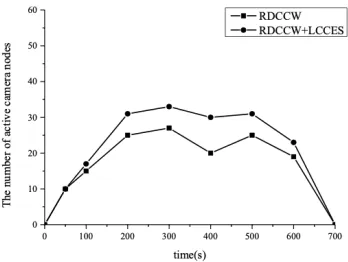
Figure 1 shows the change of the number of active camera nodes in the image acquisition process under the two conditions of RDCCW only and RDCCW+LCCES only.
Fig. 1. Changes in the number of active camera nodes during image acquisition p
o RT
It can be concluded from the figure that the number of active camera nodes is larger with the RDCCW mechanism in the image acquisition process. After adopting the LCCES strategy, on the one hand, the redundant active camera node is dormant by the redundant node distributed self-checking algorithm, which solves the problem of redundant acquisition of event images; on the other hand, the number of active camera nodes is further reduced by regular intra-grid centralized coordination, so the number of active camera nodes during image acquisition is significantly reduced, thereby reducing the amount of image acquisition.
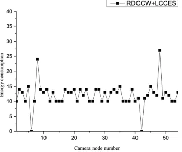
Figure 2 shows the energy consumption distribution of camera node image acquisition under two conditions: RDCCW and RDCCW+LCCES.
It can be concluded from Figure 2 that the only use of the RDCCW mechanism will result in an uneven distribution of energy consumption at the camera nodes. After adopting the LCCES strategy, it can be concluded from Figure 3 that the energy consumption of the camera node is reduced, and the energy consumption distribution of the entire node is balanced except for a few camera nodes.
Fig. 2. Energy consumption distribution of camera node image acquisition
4
Multi-node collaborative image compression algorithm
Firstly, the processing flow of two-dimensional time domain LBT transform and encoding is rearranged, which makes it suitable for multi-node collaborative implementation in WMSNs. Then based on the two-hop cluster structure proposed in the previous chapter, the LBT multi-node collaborative image compression algorithm LBT-MCIC is designed.
4.1 LBT image compression algorithm split
In the proposed LBT-MCIC algorithm, a time-domain overlapping LBT transform is adopted. The two-dimensional time domain LBT transform has traditionally performed one-dimensional transforms in the order of the preceding rows and succeeding columns.
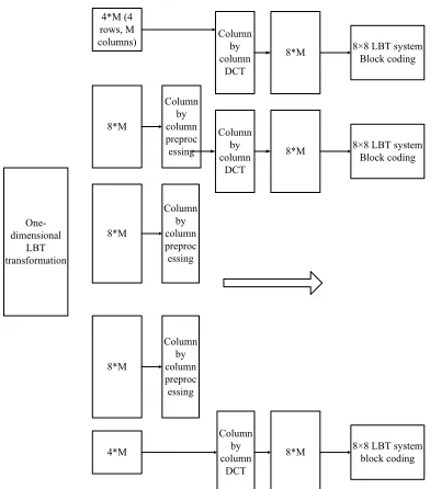
It can be concluded from Figure 4, the 8-point DCT operation requires a pre-processing result of overlapping 8 points in the neighboring domain, so there are two ways to perform the LBT transformation in one-dimensional row: do 8 pre-processing first, then 8 o'clock DCT, and then alternately, until the end of a line; first, do the pre-processing of the complete line, and then do the DCT of the whole line. There is no time-dependent dependency between the 8-point pre-processing and the 8-point DCT. Similarly, column transformations have two similar ways: first do the 8-point preprocessing of the same column, then do the 8-point DCT of the same column, and then proceed sequentially until the end of 8 lines; first, do 8 rows of pre-processing column by column, and then do 8 rows of DCT column by column.
Fig. 4. Implementation process of traditional LBT image compression algorithm One-dimensional LBT transformation 4*M (4 rows, M columns) 8*M 8*M 8*M 4*M Column by column preproc essing Column by column preproc essing Column by column preproc essing Column by column DCT Column by column DCT 8*M 8*M 8*M Column by column DCT
8×8 LBT system Block coding
8×8 LBT system Block coding
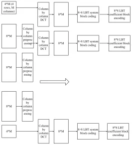
The processing flow of the two-dimensional time domain LBT transformation and encoding is rearranged, and the implementation ways as shown in the figure are obtained. That is, the pre-processing of 8 rows is performed column by column first, then 8-point DCT and row LBT processing of each row are performed column by column in the 8 rows, and finally 8×8 LBT coefficient blocks of the 8 rows are encoded. It can be concluded from the figure, all the steps after the column preprocessing process are completed in 8 rows of data. That is, the LBT image compression algorithm after the rearrangement process is split, and the column preprocessed image data can be sent to the surrounding ordinary nodes in 8 rows, and the subsequent steps are implemented by them.
Fig. 5. Implementation process of LBT image compression algorithm suitable for multi-node collaborative implementation
4.2 Multi-node cooperative implementation in two-hop cluster structure It can be concluded from Figure 6 that the implementation process of the split LBT image compression algorithm is very convenient to be implemented by multiple nodes in the two-hop cluster structure proposed in the previous section. Therefore, based on the network topology constructed in the previous chapter, the LBT-MCIC algorithm is designed. 4*M (4 rows, M columns) 8*M 8*M 8*M 4*M Column by column preproc essing Column by column preproc essing Column by column preproc essing Column by column DCT Column by column DCT 8*M 8*M 8*M Column by column DCT
8×8 LBT system block coding
8×8 LBT system block coding
As shown in Figure 6, in the multi-node collaboration process, there are three nodes: camera node, member node, and ordinary cluster head node.
Fig. 6. Implementation of LBT multi-node collaborative image compression in two-hop cluster structure
4.3 Calculation complexity and storage overhead analysis
In computational complexity, Table 1 shows the average amount of computation for each of the different transforms on each pixel. Although binLBT has a slight increase compared to binDCT, its computational complexity is greatly reduced compared to binary CDF9/7. Compared with binLBT, the fixed-point LBT only increases the multiplication operation, but the multiplication operation is more balanced with the addition, subtraction and shift operation units, which is convenient for DSP processing with parallel mechanism, and the overall calculation amount is greatly reduced.
Table 1. Comparison of average operations (number of times) per pixel for the six transformations
bin DCT Floating point
CDF9/7 CDF9/7 Binary LBT bin LBT Fixed point LBT
The number of integer
addends 7.75 0 34.125 0 15 5 The number of shifts 3.5 0 23.625 0 6.75 1.5 The number of integer
multiplier 0 0 0 0 0 1.75 The number of floating
point addends 0 10.5 0 10.5 0 0 The number of floating
point multiplier 0 7.875 0 4.625 0 0 Column time
domain preprocessing
Column DCT + Line LBT+ Encoding (8 rows
at a time)
Column DCT + Line LBT+ Encoding (8 rows
at a time)
Column DCT + Line LBT+ Encoding (8 rows
at a time)
Column DCT + Line LBT+ Encoding (8 rows
at a time)
Forward compressed stream
Forward compressed stream
The storage overhead uses the LBT image compression algorithm, and the storage overhead required is very small. Let the image width be M, and the camera node only needs to synchronously buffer 12M pixels. That is, after performing column preprocessing of 8 rows of image data each time, the first 4 rows of the 8 rows and its upper 4 rows are transmitted to the member nodes in the transition cluster, and then the following 8 rows of image data are read to continue the column pre-processing operation. The member nodes in the transition cluster only need to synchronously buffer 8M pixels each time. With the line transform-based method recommended by JPEG 2000, the 5-layer wavelet transform needs to buffer 183M pixels.
4.4 Performance evaluation
Experiments are performed with 512 × 512 × 8 bits grayscale images. If the camera node uses the LBT image compression algorithm, the transition cluster member nodes receive 8×512 pixels of data each time, which is equivalent to transmitting 64×64 pixels blocks to the transition cluster member nodes each time with the JPEG2000 image compression algorithm. Figure 7 shows the reconstructed image quality comparison with compression bit rates of 0.1bpp and 0.25bpp, respectively. The LBT algorithm uses binLBT and the JPEG2000 algorithm uses binary CDF9/7 (5-level wavelet transform). It can be concluded from the figure 7 that whether it is measured by peak signal-to-noise ratio (PSNR value) or subjective evaluation, the reconstructed image quality of LBT image compression algorithm is much better than JPEG2000 at high compression ratio, so it is more suitable for multi-node collaborative implementation in WMSNs.
Fig. 7. Comparison of reconstructed image quality between the two algorithms
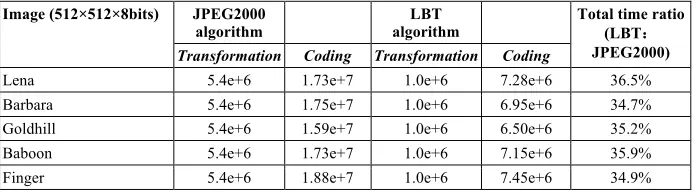
recorded by the timing aid tool in the CCStudio 3.1 environment. The JPEG2000 algorithm uses LS9/7 wavelet fixed point (3 level wavelet transform) to implement, and the LBT algorithm uses fixed point LBT. The algorithm implementation process has been optimized according to the parallel characteristics of DSP.
Table 2 shows the comparison of the number of running clock cycles for the two algorithms when the image compression ratio r is 4. According to the processor energy consumption model, the energy consumption of the LBT image compression algorithm is only about 35% of the energy consumption of the JPEG2000 image compression algorithm. Therefore, in addition to the better reconstructed image quality, the LBT image compression algorithm is adopted in WMSNs to greatly reduce the total energy consumption of the network.
Table 2. Comparison of running clock cycles Image (512×512×8bits) JPEG2000
algorithm algorithm LBT Total time ratio (LBT::
JPEG2000)
Transformation Coding Transformation Coding
Lena 5.4e+6 1.73e+7 1.0e+6 7.28e+6 36.5% Barbara 5.4e+6 1.75e+7 1.0e+6 6.95e+6 34.7% Goldhill 5.4e+6 1.59e+7 1.0e+6 6.50e+6 35.2% Baboon 5.4e+6 1.73e+7 1.0e+6 7.15e+6 35.9% Finger 5.4e+6 1.88e+7 1.0e+6 7.45e+6 34.9%
Furthermore, it is considered that a number of nodes are randomly distributed in a square area of 500 m × 500 m. The node closest to the center of the square area is selected as the camera node, and the base station position is (0, 0). The image captured by the camera node is a 512×512×8 bits grayscale image. The network life cycle of the three schemes of CC, TCIT and LBT-MCIC is compared. Therefore, compared with the TCIT solution, the network life cycle is slightly reduced; however, compared with the CC scheme, when the common nodes are deployed intensively, the network life cycle obtained from the LBT-MCIC algorithm is much larger than that of the CC scheme.
5
Conclusion
while balancing the energy consumption of the camera nodes. The problem of multi-camera node collaborative energy-saving image acquisition is studied. The simulation results show that the LCCES strategy has better performance in reducing image acquisition energy consumption and balancing camera node energy consumption. Combined with the idea of "in-network computing", a multi-node collaborative image compression algorithm based on LBT is proposed. Firstly, the shortcomings of JPEG2000 compression standard in WMSNs multi-node collaborative implementation are analyzed; then, based on this, an LBT image compression algorithm with low computational complexity and high compression performance is proposed. The algorithm eliminates the block effect by time-domain overlap transformation before DCT transformation and has the characteristics of simple calculation and low storage requirements. By rearranging the processing flow of two-dimensional time domain LBT transform and encoding, an image compression scheme LBT-MCIC suitable for multi-node cooperative implementation in WMSNs two-hop cluster structure is proposed. The experimental results show that in the multi-node collaborative implementation environment of WMSNs, the reconstructed image quality of LBT image compression algorithm is much better than JPEG2000 under high compression ratio. This scheme greatly reduces the network energy consumption and plays a role in extending the network life cycle.
6
References
[1]Kong, S., Sun, L., Han, C., & Guo, J. (2017). An Image Compression Scheme in Wireless Multimedia Sensor Networks Based on NMF. Information, 8(1): 26.
[2]Zhou, W., Sun, L., Guo, J., & Liu, L. (2016). Image compression scheme based on pca for wireless multimedia sensor networks. The Journal of China Universities of Posts and Telecommunications, 23(1): 22-30. https://doi.org/10.1016/S1005-8885(16)60004-3 [3]Bavarva, A., Jani, P. V., & Ghetiya, K. (2018). Performance Improvement of Wireless
Multimedia Sensor Networks Using MIMO and Compressive Sensing. Journal of Communications and Information Networks, 3(1): 84-90. https://doi.org/10.1007/s41650-018-0011-8
[4]Wei, Z., Lijuan, S., Jian, G., & Linfeng, L. (2016). Image compression scheme based on PCA for wireless multimedia sensor networks. The Journal of China Universities of Posts and Telecommunications, 23(1): 22-30. https://doi.org/10.1016/S1005-8885(16)60004-3
[5]Shen, H., & Bai, G. (2016). Routing in wireless multimedia sensor networks: A survey and challenges ahead. Journal of Network and Computer Applications, 71: 30-49.
https://doi.org/10.1016/j.jnca.2016.05.013
[6]Haitao, L. (2015). Research on a Multi Node Cooperate Image Compression Algorithm for Wireless Network Based on LBT Model. Open Automation and Control Systems Journal, 7: 1641-1646. https://doi.org/10.2174/1874444301507011641
[7]Pandremmenou, K., Kondi, L. P., & Parsopoulos, K. E. (2015). A study on visual sensor network cross-layer resource allocation using quality-based criteria and metaheuristic optimization algorithms. Applied Soft Computing, 26: 149-165.
[8]Adu-Manu, K. S., Adam, N., Tapparello, C., Ayatollahi, H., & Heinzelman, W. (2018). Energy-Harvesting Wireless Sensor Networks (EH-WSNs): A Review. ACM Transactions on Sensor Networks (TOSN), 14(2): 10. https://doi.org/10.1145/3183338
7
Author
Fangzhou He is a Researcher of Criminal Investigation Police University of China, Liaoning Shenyang 110854, China. His research interests include Wireless Multimedia Sensor Networks.