Ad Hoc Networking With Directional Antennas: A
Complete System Solution
Ram Ramanathan
, Senior Member, IEEE
, Jason Redi
, Senior Member, IEEE
, Cesar Santivanez
, Member, IEEE
,
David Wiggins, and Stephen Polit
Abstract—Directional antennas offer tremendous potential for improving the performance of ad hoc networks. Harnessing this potential, however, requires new mechanisms at the medium access and network layers for intelligently and adaptively exploiting the antenna system. While recent years have seen a surge of research into such mechanisms, the problem of developing a complete ad hoc networking system, including the unique challenge of real-life pro-totype development and experimentation has not been addressed.
In this paper, we present utilizing directional antennas for ad hoc networking (UDAAN). UDAAN is an interacting suite of modular network- and medium access control (MAC)-layer mechanisms for adaptive control of steered or switched antenna systems in an ad hoc network. UDAAN consists of several new mechanisms—a di-rectional power-controlled MAC, neighbor discovery with beam-forming, link characterization for directional antennas, proactive routing and forwarding—all working cohesively to provide the first complete systems solution. We also describe the development of a real-life ad hoc network testbed using UDAAN with switched di-rectional antennas, and we discuss the lessons learned during field trials. High fidelity simulation results, using the same networking code as in the prototype, are also presented both for a specific sce-nario and using random mobility models. For the range of pa-rameters studied, our results show that UDAAN can produce a very significant improvement in throughput over omnidirectional communications.
Index Terms—Ad hoc networks, beamforming, directional an-tenna, medium access control (MAC).
I. INTRODUCTION
O
VER THE PAST few years, research into ad hoc net-works has yielded considerable advances, notably in the areas of new routing and medium access techniques. Yet, sig-nificant shortcomings of ad hoc networks remain, especially when compared with wireline networks. Ad hoc networks suffer from fundamental capacity limitations [1], connectivity/surviv-ability problems, and are prone to jamming and eavesdropping. Attempts to surmount these problems at the medium access, network and transport layers by way of innovative and often ingenious protocols have yielded only incremental success. In this paper, we consider a physical layer enhancement—direc-tional communications—and its exploitation by the various components of an ad hoc networking system to address the above problems and provide a significant improvement in net-work capacity.Manuscript received October 23, 2003; revised November 8, 2004. This work was supported in part by the Defense Advanced Research Projects Agency FCS Communications Program under Contract DAAD19-01-0027.
The authors are with BBN Technologies, Cambridge, MA 02138 USA (e-mail: [email protected]).
Digital Object Identifier 10.1109/JSAC.2004.842556
Directional antennas have a number of advantages over omni-directional antennas in ad hoc networking. By focusing energy only in the intended direction, directional antennas can increase the potential for spatial reuse and can provide longer transmis-sion and reception ranges for the same amount of power. In-creased spatial reuse and longer range translates into higher ad hoc network capacity (more simultaneous transmissions and fewer hops), and longer range also provides improved connec-tivity. Further, since the spatial signature of the energy is re-duced to a smaller area, chances of eavesdropping are rere-duced, and with “smart” antennas, the steering of nulls can allow the suppression of unnecessary interference (such as jammers) at the receiver.
Replacing an omnidirectional antenna by a directional one in an ad hoc network is not by itself sufficient to exploit the of-fered potential. The antenna system needs to be appropriately controlled by the each layer of the ad hoc networking protocol stack. Such control includes pointing in the right direction at the right time for transmitting and receiving, controlling the transmit power in accordance with the antenna gains, etc. Fur-ther, mechanisms that were designed with omnidirectional com-munications in mind—for example, medium access, neighbor discovery, and routing—have to be redesigned for directional antennas. Finally, modifications to such network mechanisms can interact with each other—for instance, medium access con-trol may require knowledge of the antenna beam to use for a particular neighbor discovered by the neighbor discovery mech-anism. Thus, in order to realize the full potential of directional antennas, new protocols at various layers of the stack have to work in concert to create a complete system solution.
We present the first such complete system for ad hoc net-working using directional antennas, called utilizing directional antennas for ad hoc networking (UDAAN). While previous works have targeted specific solutions for directional antennas, such as medium access, there has been no published work on designing, implementing and field testing a complete system that uses directional antennas. Our work has not only resulted in novel networking mechanisms but has also demonstrated a complete system in a variety of field tests.
The remainder of this paper is organized as follows. In the next section, we summarize some related works. We follow that by introducing some preliminaries on directional antennas and UDAAN terminology. Each of the component modules are then described in the next few sections—MAC in Section IV, neighbor discovery in Section V, link characterization in Section VI, and routing and forwarding in Section VII. Our simulation environment and results of simulations of the field
demonstrations, as well as randomly generated scenarios are presented in Section VIII. Our field demonstrations and lessons learned are described in Section IX. Finally, Section X summa-rizes our work, with some concluding remarks.
II. RELATEDWORK
Much of the work on medium access has been done in the context of extending carrier sense multiple access/collision avoidance (CSMA/CA) (in particular, IEEE 802.11) to work with directional antennas. This includes [2]–[5]. In [2], multiple fixed directional antennas are considered and the IEEE 802.11 protocol is executed on a per-antenna basis. Steered beams are considered in [3], where the main innovation is the use of a “short network allocation vector (NAV),” to exploit the increased opportunity for spatial reuse. A “directional NAV” was proposed in [4], and independently in [5]. The key idea is that if a node receives an request-to-send (RTS) or clear-to-send (CTS) from a certain direction, then it needs to defer for only those transmissions that are in (and around) that direction. In [5], the authors also discuss a multihop RTS scheme to bootstrap the handshake when to transmit, as well as receive directionality are required to close the link. Medium access approaches are also discussed in [6].
A small amount of work exists in the area of time-division multiple access (TDMA) using directional antennas [7], [8]. In [7], the authors study the performance of ad hoc networks with a TDMA MAC and two kinds of beamforming antennas—beam steering and adaptive beamforming. In [8], a distributed algo-rithm is given that only uses two-hop information for sched-uling, thereby making it scalable, yet implementable for mobile ad hoc networks.
The study of directional antennas for aspects of ad hoc networking other than medium access is limited. The use of directional floods to limit the scope of route requests in an “on-demand” ad hoc routing protocol is suggested in [9] and explored in [10]. A broad-based study of the performance potential of directional antennas in ad hoc networks appears in [6].
III. PRELIMINARIES
Radio antennas couple energy from one medium to another. Anomnidirectional antenna(sometimes known as anisotropic
antenna) radiates or receives energy equally well in all direc-tions.1Adirectional antennahas certain preferred transmission and reception directions, that is, transmits/receives more energy in one direction compared with the other.
Thegainof an antenna is an important concept, and is used to quantify the directionality of an antenna. Informally, gain mea-sures the relative power in one direction compared with an om-nidirectional antenna. Thus, the higher the gain, the more direc-tional is the antenna, and smaller the beamwidth.
Antenna systems, at least for the purposes of this paper, may be broadly classified into switched and steered antennas sys-tems. Inswitched antennasystems, one of several fixed direc-tional antennas can be selected using a switch. One may also use
1In reality, no antenna is perfectly omnidirectional, but we use this term to
represent any antenna that is not intentionally directional.
a phased array antenna and a beamforming “matrix” to generate multiple fixed beams to get a switched antenna (beam) system. The transceiver can then choose between one or more beams for transmitting or receiving. While providing increased spa-tial reuse, switched beam systems cannot track moving nodes which, therefore, experience periods of lower gain as they move between beams. In asteered antennasystem, the main lobe can be pointed virtually in any direction, and tracking of the loca-tion of the node may be done automatically using the received signal from the target and sophisticated “direction-of-arrival” techniques.
Our description of UDAAN protocols is in terms of fixed directional antennas and one omnidirectional antenna. However, they are just as applicable to steerable antennas. That this adap-tation is straightforward can be seen from the logical equiva-lence of switched and steered antenna systems with respect to a given transceiver. Specifically, a command to switch to antenna in an -antenna switched system may be transformed (trans-parently to UDAAN protocols), to steer to “position ,” which is aligned directionally with antenna . By making high enough to accommodate the granularity of steerability, one can use any algorithm that supports switched antennas to work with steered antennas.
UDAAN supports communication over multiple frequency bands, up to a maximum of 32 frequency bands. Each band is assumed to be serviced by a separate radio transceiver and a separate instantiation of the medium access control mechanism. Most of the mechanisms described in this document are agnostic to whether the antenna system uses switched or steered beams. This is done by using the transmission direction as the unifying abstraction—in a steered beam system, the beam is steered as close as possible to the specified direction; in a switched beam system, the antenna or beam that has the lowest angular separa-tion from the specified direcsepara-tion is selected. Recepsepara-tion is similar. This makes the design and implementation portable to switched, as well as steered beam antennas.
In our prototype implementation, we have used an inertial management unit (IMU), which is a hardware module that sup-plies position (geo-location), as well as orientation information to a high degree of accuracy. Further, each node also has access to three-dimensional (3-D) antenna patterns that it uses. Using the antenna patterns, along with the positions of the antennas on the vehicle, and orientation information from the IMU, the node can calculate nearly precisely the gain in any given direction.
We indicate the antenna method used for exchanging packets as either no beamforming (N-BF), transmit beamforming
(T-BF), or transmit and receive beamforming (TR-BF). The use of the term “beamforming” indicates the use of a direc-tional antenna (either switched or steered). Therefore, “no beamforming” means that the transmitter and the receiver use omnidirectional antennas, while transmit beamforming means that the transmitter uses a directional antenna, but the receiver uses an omnidirectional antenna.Linkprofilesare used by mod-ules to express how a neighboring node can be communicated with. The linkprofile is a tuple ofband, beamform. For example, we allow up to six link profiles per neighbor for a two-band system.
The radioprofile is a radio specific structure that describes the parameters such as power, antenna number, datarate, etc., that the radio layer should use for transmission.
When a packet is received or transmitted by the radio layer, atracerecordis generated which describes the event in a radio-specific structure which includes items such as the antenna the packet was received or transmitted on, the datarate used, and other items. Tracerecords describe individual transmission at-tempts, promiscuous receptions of packets, control packet [RTS, CTS, acknowledgment (ACK)] transmission or receptions, as well as the transmission and reception of data packets. Tracere-cords are stored in a circular set of buffers in the radio driver for queries by the protocols.
IV. MEDIUMACCESSCONTROL(MAC)
Our directional medium access control (D-MAC) protocol is a novel variant of the single-channel CSMA/CAapproach. Sev-eral protocols published in the literature are representatives of this approach, including the IEEE 802.11 distributed coordina-tion funccoordina-tion (DCF) standard for wireless local area networks (LANs) [12]. The basic idea is that, in addition to sensing before transmitting, the sender sends a RTS and the receiver responds with a CTS as a prelude to data packet transmission. Nodes hearing this exchange defer for the subsequent DATA-ACK ex-change. Refer to [12] for details.
Modifications of traditional MAC protocols such as 802.11 to support directional antennas, typically referred to asdirectional MAC, have been studied previously (for instance [2]–[5]). Two novel features of our solution differentiate it from previous so-lution approaches. The first is the use of a backoff procedure, where both the interval boundaries and the method of backoff depends upon the event (e.g., no CTS, no ACK, channel busy) that caused the backoff. The second is the tight integration of power control with direction control. As shown in [6] and other works, judicious power control is critical to exploiting the poten-tial of directional antennas. Thus, for instance, our (directional) NAV table includes power values.
Our MAC protocol is designed to be simple enough to implement within a short time in a real-life prototype, while harnessing most of the spatial-reuse benefits of directional antennas. Thus, rather than build in complex protocol features to eliminate all collisions, the protocol controls the collisions using judicious backoff schemes to achieve high throughput in practice.
We now describe the UDAAN D-MAC protocol. First, for simplicity, we describe the control flow and backoff schemes without virtual carrier sensing and power control. Following that, in Section IV-B, we describe the virtual carrier sensing and power control mechanisms.
A. D-MAC Control Flow
The D-MAC has four types of packet transfer modes, each with a different set of primitives. In particular, a packet transfer may have just the DATA, an RTS followed by the DATA,2DATA
2This was designed to allow the receiver of a broadcast DATA to increase
its signal-to-interference plus noise ratio (SINR) by beamforming toward the sender after receiving the RTS.
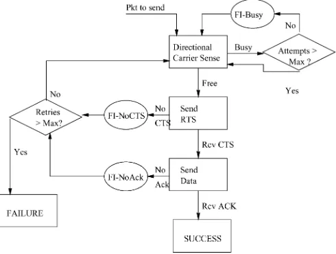
Fig. 1. High-level flow chart of D-MAC.
and ACK only, or the full RTS-CTS-DATA-ACK. We shall only describe the last case here as it largely subsumes the others. All packets contain the position of the transmitting node so the receiver can immediately know the most up-to-date direction for a response.
The D-MAC is by default in idle state. In this state, the D-MAC is in receive mode, switched to the omni antenna. There are two kinds of idle states—natural idle and forced idle. In natural idle, the D-MAC has no packets to send, and is simply waiting for something to “happen.” A forced idle is entered when a node has something to send but is forced by the protocol to desist for some reason (as explained later).3
The general control flow is illustrated in Fig. 1.
When a node has a packet to send, it does directional car-rier sensing (DCS) on the antenna corresponding to the desti-nation for a randomly chosen period called theDCS period. If the channel is free for the duration of the DCS period, then the node sends an RTS. After the RTS is sent, the node listens on the same directional antenna and receives the CTS, sends the DATA and receives the ACK. All of this is done directionally. Reception of the RTS is done omnidirectionally, after which the receiver switches to the best directional antenna for DATA.
If the DCS finds the channel busy, then it goes into a forced idle period (refer Fig. 1) “FI-Busy” up to a certain number of times, after which it persists sensing the channel and transmits as soon as the channel goes free. While this may seem unusu-ally aggressive, this works well for a couple of reasons. First, it prevents unfairness that happens when two very busy nodes al-ternate in transmission, blocking another node out. Second, by upper bounding the delay on transmission as much as possible, it prevents deadlock that can happen if one direction is exces-sively busy and prevents transmission to other directions.
The node goes into a forced idle if one of the following hap-pens: the channel is busy, a CTS is not received, or an ACK is not
3In most respects, the forced idle concept is similar to backoff. However, the
TABLE I
FORCEDIDLECONTROL. THEROWSINDICATE THEEVENTS FORWHICH THEFORCEDIDLEISEXECUTED. THECOLUMNSINDICATEHOW THEVALUES OF RUNNINGVARIABLESLOWFIANDHIGHFI ARERESET,AND THECONTENTIONWINDOW(CWMIN ANDCWMAX) USED FORTHATEVENT. FOR THE
FI-BUSY,THECONTENTIONWINDOWONLYAPPLIES IF THEATTEMPTNUMBERISLESSTHAN ACONFIGUREDTHRESHOLD, OTHERWISE,THE NODEBECOMESPERSISTENT(SEEFIG. 1). THEA ; A ; C ; C ; B ; B ,ANDA ARECONFIGURATIONPARAMETERS
THATCONTROL THEINITIALIZATION ANDGROWTH OF THECONTENTIONWINDOW. THEYWEREDETERMINEDUSING ACOMBINATION OFNUMERICALANALYSIS ANDSIMULATION-BASEDTUNING
received. In forced idle, the node is switched to the omni antenna and may receive packets, respond to RTS, etc., but may not ini-tiate its own RTS or DATA. A forced idle period ends at the later of the completion of such communications and the expiration of a timer that is set when entering forced idle. A “contention window” is maintained and reset after each entry–exit sequence from the forced idle. The timer value is a random number within this contention window. As mentioned earlier, the way the con-tention window is reset depends upon the particular event. This is captured in Table I, and explained next.
Two running variables HiFI and LowFI are maintained, along with several preconfigured constants, as explained in Table I. The last column shows how the contention window changes upon each successive occurrence of the event. Thus, as men-tioned earlier, if the channel is busy, the node backs off, tries again (no change in the window) and repeats this until a cer-tain number of attempts is exceeded in which case the RTS is sent anyway (see Fig. 1). Similarly, if there is no CTS received, the node backs off using a “linear increase” and if there is no ACK received, the node implements an “exponential increase” and “exponential decrease” of the contention window.
Finally, after the ACK is received, the node goes into a forced idle to give other nodes a chance. This forced idle is set as per Table I (row FI-Ack).
B. Power Control and Virtual Carrier Sensing
The first RTS for a given packet is sent at the power indicated in the radio profile (or maximum power if none is specified). The transmit power of subsequent RTSs (that is, upon failure to receive CTS or ACK), is increased for each retry by a con-figured value. The RTS contains the power and its current re-ceive threshold . Then, the CTS is sent with a power equal to , where is the received signal strength indication (RSSI) of the received RTS packet, and MARGIN-POWER is a margin to account for fades, etc. The DATA and ACK are power adjusted in a similar manner.
Virtual carrier sensing, that is, the tracking of transmissions beyond sensing range using overheard RTS/CTS, is typically done by means of a NAV table. Directional virtual carrier sensing, or D-NAV has been suggested in both [4] and [5]. The basic idea is to augment the traditional NAV using a direction (or in the case of fixed antennas, an antenna) field, indicating that the NAV applies only for that direction. We extend the idea further by incorporating power control as an integral part of the NAV, as follows.
The D-NAV table contains, in addition to the duration field, the antenna number,4and theallowed power. This field indicates the power above which interference will occur. It may be used to transmit if it is deemed (see below) that the intended trans-mission is sufficiently low power so as to not bother the busy nodes.
Theallowed powerfield is set as follows. Only RTS/CTS re-ceived when the node is in idle (omni) are processed for NAV. When an RTS (CTS) is received, theallowed poweris set as the smaller of the currentallowed powerand
VCSMarginPower, where is the transmitted power of the RTS (CTS) [indicated in the RTS (CTS)], is the received power, is the current receive threshold of the sender of the RTS (CTS), andVCSMarginPoweris a configured parameter to account for fades, etc.
When a packet is to be transmitted with a power , the following deference procedure is employed. If
allowedPower , then the packet
is allowed to be transmitted, regardless of busy indication of the antenna. Here, is the gain of the antenna that is intended to be used for transmission, and is the gain of the omnidirectional antenna. This is required because the RTS and CTS are received on omni. Otherwise, the node defers for a period indicated by the duration field in the NAV table.
V. NEIGHBORDISCOVERY
In order to exploit the longer range advantage of direc-tional antennas, UDAAN incorporates directional neighbor discovery, that is, the ability to discover neighbors that can only be reached if one or both of the nodes use beamforming. As mentioned earlier, UDAAN has three kinds of links/neighbors in each band: N-BF (without beamforming), T-BF (using transmit-only beamforming), and TR-BF (using transmit and receive beamforming).
The hard problem in directional neighbor discovery, such as for T-BF and TR-BF linkprofiles, is in determiningwhere to point, andwhen to pointthe antenna for transmit and/or receive. For instance, TR-BF neighbors can be discovered only if both the transmitter and the receivers point toward each other at the exact time a heartbeat is sent.
We have developed two methods for this problem:informed discoveryandblind discovery. In informed discovery, a node
4We say antenna number because we are using a switched antenna
has available some form of information about a nonneighbor that will enable pointing. For instance, might have the geo-lo-cation of piggybacked through routing updates, or an explicit position information protocol [13]. Informed discovery is pos-sible when the entire network is connected, and may be used, for instance, when we wish to utilize a long-range single-hop T-BF link instead of several shorter range multihop N-BF links be-tween two nodes. In blind discovery, a node is not even aware of the existence of a node . Conventional (N-BF) neighbor dis-covery is a form of blind disdis-covery. Blind disdis-covery for T-BF and TR-BF links is, however, far more challenging, yet the only approach when the network is disconnected, and we need to create links across the partition(s).
Given three modes (N-BF, T-BF, and TR-BF), and two methods (informed and blind), there are six potential neighbor discovery mechanisms. Of these, informed N-BF is a trivial case, and blind T-BF is a specific case of blind TR-BF (as will be apparent later). Informed TR-BF has been considered earlier (although not by that name) in [5]. Thus, we now describe three neighbor discovery mechanisms, namely, (blind) N-BF, informed T-BF, and blind TR-BF. These operate in parallel in steady state, but are typically started in the order mentioned.
All three of the UDAAN neighbor discovery mechanisms are based on sending and scoring heartbeats, which are periodic control messages broadcast by each node. A heartbeat includes the sending node identifier, the band, the mode (N-BF, T-BF, or TR-BF), and depending on the mode, one or more neighbors considered “up” by this node.5The neighbor discovery mecha-nisms that follow are executed independently for each band and, therefore, we do not consider this field any further.
When a node is activated, it first performs N-BF discovery. Specifically, heartbeats with mode set as N-BF are broadcast using the omnidirectional antenna, and heartbeats received from other nodes are scored. The heartbeat contains the iden-tifiers of all of the neighbors from which it has received an adequately scored set of N-BF heartbeats. This is similar to traditional neighbor discovery and creates an N-BF links-based topology.
Routing updates (sent by the routing module), triggered by links declared as being “up” are then disseminated. These up-dates contain the position of the sending node. As a result, a given node may get to know about the existence and position of a node that is out of N-BF range. For each such node , node performs (informed) T-BF discovery. Specifically, node sends a directional heartbeat to the target . The heartbeat sets the mode field as T-BF, and contains the position of and also whether considers to be “up.” Note that for T-BF, the heartbeat only contains information about the intended target not all neighbors. Assuming that is within T-BF range and it is idle, the heartbeat is received (omnidirectionally), and the po-sition of is extracted. Using this position information, node then beamforms toward sends a directional heartbeat. If and when sufficient scores on the heartbeats are achieved on and , a T-BF link profile is established between and .
5A nodeXconsiders a nodeYto be “up” if a scoring function on the number
of heartbeats received fromY is above a threshold. The exact scoring func-tion is beyond the scope of this paper, but basically, a sliding window-based “k-out-of-n” scheme is used.
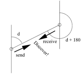
Fig. 2. Blind TR-BF discovery.
We note that in some cases, transmitting in the direction de-termined using the relative positions may not be the best way to communicate. For example, when there is an obstacle in the line-of-sight, one may be able to use reflected paths around the obstacle, and this may imply pointing in a different direction. Exploiting reflected paths is not possible with simple switched beam antennas. It requires adaptive arrays which were not part of the target system. Hence, our neighbor discovery mechanism did not incorporate that feature.
For nodes that are not reachable through N-BF or T-BF, we can perform blind TR-BF discovery. A high-level design is as follows. The main challenge with blind TR-BF discovery is to get two nodes that do not know of each other’s existence to beamform toward each other simultaneously. To accomplish this, we require that the clocks on all of the nodes are syn-chronized with each other, as might be the case if the common clock source is GPS. Periodically, all nodes engaged in blind TR-BF discovery do the following (at the same time). A direc-tion is chosen based on the time—imagine one of the hands of an analog clock. Each node alternates randomly between sending heartbeats in that direction and listening in the opposite direc-tion for such heartbeats.
For example, at a certain point in time that corresponds to 1 o’clock in the imaginary analog clock, all nodes point to-ward 30 east of due north to send heartbeats and 30 west of due south to receive heartbeats. As seen in Fig. 2, for any two nodes, when the direction matches the angle between the nodes, this scheme will cause the transmit beamforming of one node to align with the receive beamforming of the other and create an opportunity for the nodes to transfer a heartbeat. The mode field in the heartbeats is set as TR-BF, and all neighbors perceived to be “up” by TR-BF are included in the neighbor list. As usual, the position of the sending node is included in the heartbeats. After at least one heartbeat is exchanged in each direction, each node knows the position of its potential TR-BF peer, and can send fur-ther heartbeats directly by pointing in that direction and, thus, maintain the link.
VI. LINKCHARACTERIZATION(Linkchar)
The link characterization (Linkchar) module is designed to take information from the link-layer interface and summarize it into a set of metrics for use by other modules. With the excep-tion of occasional requested probes, Linkchar does not send any traffic to test the link, but relies on the traffic sent or received by other modules and the Internet protocol (IP) applications. Linkchar will send an occasional ping-like packet to test a link if it has not received any packets from a neighbor within a pre-defined amount of time. The idea of this packet is to test whether a neighbor is still there or not in the presence of lost heartbeats. This is done notwithstanding the presence of heartbeat packets because the point-to-point ping packets have a higher likelihood of reliable transmission because they are sent using a directional antenna, and they are acknowledged.
The minimum required energy for transmitting on a link is a very useful metric because it gives insight into the error rate, available throughput, and stability of a particular linkprofile. Linkchar determines the minimum required energy and provides this, as well as a tightly quantized version of the required energy to the routing module. The quantized value is used in the SPF calculation for determining the best paths for routing packets. We use this quantized version of the metric in an attempt to take packets that have a high signal-to-noise ratio (SNR), but at the same time not taking as many additional hops as we might if we were using strict minimum energy routing (e.g., no quantization). For the particular hardware and mobility sce-narios we experimented with, our quantization was such that an energy metric of 13 dB over the minimum required was quantized to a value of 20, an energy of 17 dB over the min-imum needed was quantized to a value of 10, and an energy of 20 dB over the minimum was quantized to a value of 1. The reason for the wide range of values is that we want to avoid using any links that are below a certain threshold, unless they are the only links available, while at the same time we do not want to resort to min-energy routing (no quantization) because this typically causes packet to travrse over many more hops than minimum. Note that the routing module also receives the exact (nonquantized) minimum energy and uses that directly for packet-by-packet power control of the MAC layer.
If we assume relatively symmetric pathloss between two nodes and , then we can use the packets received at from to determine the amount of energy needed by to send a packet back to . To do this, we need to know the transmit power, the received power, and the antenna gains for that packet. We include the transmit power in each MAC packet which is then provided to the protocols via tracerecords. In a directional antenna system, determining the appropriate antenna gains is critical because: 1) transmitter and receiver may be using different antennas and 2) direction of the antennas are pointing (regardless of steered or switched) may not be the exact direction of the corresponding receiving/transmitting node, especially, if the packet is received promiscuously.
Within each packet the MAC layer includes the particular an-tenna that was used, as well as the angle relative to true North that the antenna was pointed. The packet also includes the lo-cation of the sending node. When Linkchar at the receiver
pro-cesses the tracerecord, it determines the line composed of the sender and receiver, and determines the angle between that line and the direction relative to true North that each of the sending and receiving antennas were pointed. Linkchar then uses these angles to lookup the appropriate gains from a preloaded 3-D table of all gains for all possible antenna patterns in use.
The instantaneous required power at a particular time is only guaranteed to be useful at the time that it was determined. To use that value in a metric, it needs to filtered and combined with other values. Since we generate datapoints based on received packets, input to a filter will be highly aperiodic and time cor-related. The use of an averaging or low-pass filter throws away most time information with the data points and is, therefore, in-appropriate for this kind of data. Instead, we use a linear predic-tive filter with a recursive least squares algorithm [15]. Similar to a Kalman filter, this filter dynamically updates the coefficients for a linear equation, which expresses the change of values from one time to another. This allows us to linearly extrapolate from the times of previous data to the current time that we wish to use the output data of the filter. Since it is a least squares filter, it also provides amean squared error(MSE), which can tell us if the filter has “converged.” Having such value is critical for metrics that can vary widely and have unpredictable input data points because they tell us whether the value reported seems to be valid, given recent trends, or not. In our case, if the MSE is beyond a particular amount (usually, 6 or 9 dB) routing opts to ignore the value and use maximum power for the MAC’s power control algorithm instead.
We note that the filter is used to predict the right power neces-sary only for the first packet in the exchange (RTS for an RCDA exchange, Data for a DA exchange). The packets following the first packet in the exchange calculate the instantaneous power necessary based on the first packet, since that is now a known, accurate and timely measurement (see Section IV-B).
Linkchar additionally provides a congestion metric for biasing against paths which are typically heavily loaded with traffic. The idea is an attempt to determine the amount of time already being used at this radio/band for transmitting or receiving packets. With this method, we do not take into account promiscuous packet data because with directional antennas, there is no guarantee that anything we overhear will affect our outgoing transmissions to other nodes. Also, this is a node-based, not link-based metric because outgoing transmis-sions and incoming receptions affect all links of a particular band since we only have one transceiver per band. The measure of busy time at the transceiver is not meant to be perfectly accurate. If it were, we would need to also include exact counts of the backoff time and an estimate of how often the MAC has to sense the channel before it can send. Instead, we use a rough estimator, that while not perfect, provides a reasonable tradeoff between complexity and utility.
We take a particular window of time (in seconds). We then subtract the amount of time used for transmitting and receiving packets to us. We do this by observing the tracerecords that ar-rive from the radio over this window of time in the following way.
is the data rate of the packet. We also add the length of
time of RTS , the CTS , and the
ACK . The tracerecords indicate whether the
mode the packet was sent at (D, D/A, R/D, and RCDA) so in some cases the effective size for these extra control packets can be considered to be zero. Note that the date rates between the RTS/CTS, the ACK, and the data packets might be different.
For each transmitted packet of bits, we include the control packet times, but also include the average forced idle time . So the total time for a single transmitted packet is num
. Note that it is important to include failed packets, as well as successfully transmitted packets, since failed packets also take up time at the transceiver.
For each window, we sum the total time taken by all the re-ceived and transmitted packets as described above and subtract it from the window time. The amount left over is the residual transmit time . Higher can be considered “better” than
a low .
It is important to note that this metric works by exploiting a characteristic specific to our directional antenna MAC—hidden terminal protection is not achieved by nodes staying quiet when their one-hop neighbors send an RTS or CTS packet, as they would in an 802.11-style omnidirectional system. By using DNAV, the reception of an RTS or CTS only blocks that partic-ular direction and receiver node, not all one-hop neighbors. If this metric was used in an omnidirectional system, one would have to additionally consider all the traffic sent and received by a node’s one-hop neighbors because in an omni system one-hop neighbors directly affect when a node can transmit.
VII. ROUTING ANDFORWARDING
Thus far, we have considered mechanisms—medium access, neighbor discovery, and link characterization, whose scope is for the most part “local” in nature, that is, confined to imme-diate neighbors. An ad hoc network, however, requires mecha-nisms for discovering routes and forwarding packets along these routes. In this section, we first briefly describe the UDAAN routing protocol and then discuss how control and data packets are forwarded. Since these are not significantly different from routing and forwarding in a traditional (omni-only) ad hoc net-work, our description here will be brief.
Routing in UDAAN is based on the hazy sighted link-state (HSLS) routing protocol. HSLS is a scalable, nonhierarchical, and simple routing protocol that has been well studied and un-derstood [11], [14]. Very briefly, HSLS limits the propagation of link-state updates so that the timeliness of the information is a linear function of the number of hops. This is done by setting the dissemination radius (“time-to-live”) of a link-state update such that the frequency of updates with radius is inversely pro-portional to . A detailed description may be found in [14].
The routing module initializes and updates next-hop for-warding tables for use by the forfor-warding module. The route generation utilizes the metrics assigned by link characterization to support type-of-service (ToS)-based routing. Three types of service are supported, which have varying reliability and delay constraints.
We now consider forwarding. The purpose of the forwarding module is to use the set of tables provided by other modules for use in forwarding, sourcing and sinking packets. This includes application data packets (both originated and in-transit), as well as control packets. Each protocol module (such as routing, link characterization, neighbor discovery) provides a set of radio-profiles to the forwarding module for use in forwarding its own control traffic. When a module sends a packet, the sending call it uses indicates the index of a specific radioprofile, as well as the ToS value for the control packet. The ToS value is used within forwarding to map to a particular queueing discipline or priority queue.
The routing module provides this table of radioprofiles for its control messages, but also provides another set of tables for use in forwarding application traffic: It first provides a ToS-to-nexthop table, which is used to indicate which nexthop table, of potentially many, maps to specific ToS values in an IP packet. Forwarding then uses the packet’s destination address as an index into this ToS-specific nexthop table. The entry in the table provides an index into a ToS-specific neighbor table. The neighbor table contains the actual nexthop address for this ToS/destination pair, as well as a specific radioprofile. The ToS value in an IP packet is also used in a ToS-to-queueing discipline table so that different types of service receive potentially different methods of queueing (such as priority). Forwarding finally enqueues the packet on the appropriate queue in a structure that includes the radio profile.
VIII. EXPERIMENTALRESULTS
We have used OPNET for the simulation results presented here. We used the exact same networking protocol code in our simulations as in the fielded testbed (except for the MAC which was implemented in a real-time operating system in the field and, therefore, needed to be reimplemented within the OPNET simulation environment). The simulations are, therefore, of very high fidelity. The disadvantage is that simulations take very long to run, thereby reducing the number of data points that can be generated in a given time.
All simulations are with a 20 node ad hoc network. The nodes are placed randomly in a 2-D square area of varying size de-pending upon the density parameter. Mobility is similar to the random waypoint model, but nodes do not stop at waypoints.
For all of the results presented in the network, 20 streams are originated, one per node, with the destination chosen randomly. Each stream consists of packets of size 8192 bits and the inter-arrival time is uniformly distributed around a mean rate of 10 packets-per-second (pps) per stream for some experiments and 50 pps for some others. In particular, graphs in Figs. 3 and 4 used 10 pps, while graphs in Figs. 5 and 6 used 50 pps to better accentuate the differences. The raw bit rate of the radio for the random scenarios is 11 Mb/s. The throughput is computed as the total number of bits delivered successfully at the destina-tion. The N-BF and T-BF modes of discovery were utilized for all of the results.
Fig. 3. Throughput dependence on density.
factor of about 10 (at density 5). Throughput increases with in-creasing density with and without directional antennas, though the directional case begins to level off at density 10. The main reason for the large throughput difference here is due to the fact that the network is not as well connected when omnidirectional antennas are used as with directional antennas (thanks to the longer links provided by directional neighbor discovery).
The throughput versus speed graph (Fig. 4) also shows about a factor of 8–10 improvement in throughput with the directional antenna. The throughput in each case is largely unaffected by speed, because for the range of speeds tested, the hazy sighted link state routing was able to adapt quickly enough.
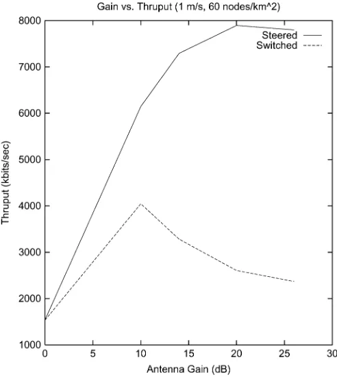
Fig. 5 compares throughput using switched and steered antennas as a function of antenna gain. An important fact to note here for the switched antenna curve is that the number of antennas is kept constant. Thus, when gain is increased (and beamwidth is decreased), the azimuthal “coverage” (the fraction of the 360 plane with at least 0-dBi gain) goes down. Interestingly, as gain increases, the performance of switched antenna still increases up to a certain gain value (10 dBi) indi-cating that the increased gain makes up for the lost coverage, but after that the decreased azimuthal coverage starts to hurt us. For steered antennas, this issue does not arise as the beam can be pointed wherever desired. Thus, the performance continues to increase with gain. Predictably, steered antenna provides better throughput than switched antennas, but the difference is not high at low gains (and probably will not be at higher gains too, if the number of switched antennas is increased commen-surately). However, in some cases, cost and bulk imposes a constraint on the number of antennas that can be used. In such cases, Fig. 5 may be useful in determining what the gain of each antenna should be for best throughput performance.
Fig. 4. Dependence on speed.
Fig. 5. Effect of antenna gain.
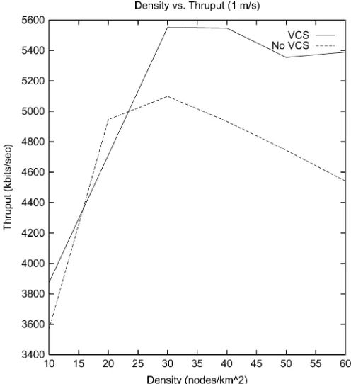
Fig. 6. Effect of VCS.
not being utilized sufficiently, there are not as many collisions even without VCS and so the difference is minimal. After a den-sity of approximately 30 nodes per sq. km when the utilization is higher, operating without VCS causes decreasing throughput as density increases, whereas VCS helps keep it more or less steady. At 60 nodes per sq. km, having UDAAN VCS increases throughput by about 17.3%.
IX. FIELDDEMONSTRATIONS
Six months after beginning the research into the UDAAN pro-tocol design, we were given a deadline of five months to build, integrate, and test the protocols in a government defined set of field experiments. The intention of the tests was to measure the quantitative gains of using directional antennas over existing omnidirectional ad hoc networks.
Specifics were defined for the 3 h, 20 node tests that included the exact locations over time, vehicle routes, vehicle speeds, and traffic loads. Each vehicle in the test was given a govern-ment laptop that sourced and sunk traffic, and each vehicle was driven by a government representative to insure that the sys-tems were truly operating autonomously and motion was un-biased. The system was graded on the throughput, packet loss rates, and delay of individual traffic flows through the network, as described in the simulation section.
The tests were conducted in a sparsely used 4 km 3 km area, which provided little other vehicle traffic to contend with. The area consisted of around 1/3 pine tree forest corridors, 1/3 sparsely clustered 2–4 story buildings, and 1/3 wide open air-field. The vehicle trails varied from paved roads over flat areas to rarely used dirt paths over hilly terrain.
The first field test utilized 20 ground vehicles outfitted with a single 2.4 GHz radio each. The government provided a base-line performance to beat by running their own 20 node test using NRL’s version of OLSR, 6-W power amplifiers and 6 dBi antennas.
Inside each of our vehicles, the UDAAN protocol software (neighbor discovery, link characterization, routing, and for-warding) was hosted on a laptop, while the D-MAC software ran in RT-Linux on a processor, which was part of a custom radio board which utilized a standard CDMA 802.11b 2.4-Ghz RF front end as the PHY layer.
Our UDAAN protocol software was hosted on laptops. The output of the radio was fed to a 6-W 2.4-GHz power amp whose output then went to an antenna switch which fed multiple antennas. Lines were run from the to the antenna switch so the MAC could switch between antennas on a packet-by-packet basis. Multiple switched antennas were used instead of an adaptive array or other steered antenna due to time and cost limitations. For this first demonstration, we used a single omni antenna with 6-dBi gain plus four directional antennas which had 10-dBi gain at boresight and 6-dBi gain at the 45 crossover points. Antennas were mounted with one pointing front, one pointing back, and one on each side. All the antenna patterns were measured at 0 elevation so we could use the exact antenna patterns in the simulation, as well as have the Linkchar module back out, receive, and transmit antenna gains for use in estimating link quality.
Our system soundly beat the omnidirectional OLSR network tested by the government, particularly, in terms of delay, but also in terms of throughput capacity.
The second demonstration added a helicopter node, the addi-tion of high-band (38 GHz) at five of the ground nodes and the helicopter node, multicast requirements, and ToS-based metrics. This demonstration also consisted of 20 nodes, but they were more scattered throughout the area.
The 38-GHz radio system had 22 antennas with 16 dBi gains each. The antennas could be actively combined to have a receive “omnidirectional” capability, but on transmit this meant that we had to divide the power amp among all antennas, and on receive the combination of multiple out of phase signals combination caused the receive gains to be effectively zero. The gain of the 38 GHz antennas was high at all elevations, but very rapid loss off the main lobe. This meant that roll, pitch, and yaw could sig-nificantly effect which antenna was the right one to use. Because of this, we offloaded the work of the MAC of the 386 to a Pen-tium-II 850 MHz running RT-Linux, so we could support cal-culation of 3-D Euler angles between each and every primitive. For assisting in communications with the helicopter, we also added a fifth 2.4-GHz antenna that pointed directly skyward. A switch matrix gave us the possibility of having all five antennas engaged for an omni function or just the four outward pointing antennas (Figs. 7 and 8).
The following are a few of the lessons we learned from our demonstration test experiences.
Fig. 7. Row of demo 1 vehicles. Mounted on top of each vehicle are four directional antennas, an omni antenna, and a mast holding the GPS device away from the vehicle.
Fig. 8. Demo 2 vehicle. Mounted on the roof are three high-band antennas and amplifiers in three 120 spaced boxes. There is also a low-band switching matrix and the low-band antenna. For this second demo, the low-band was changed to a “gumdrop” antenna that contained five antennas pointing front, back, left, right, and up.
noise. Increases in performance are not necessarily gained from higher gain antennas unless the average front-to-back and front-to-side gain ratios are high.
• When switched beams are used in conjunction with an om-nidirectional beam, sufficient overlap must exist between the directional beams so that the choice of a directional antenna never results in a poorer gain than an omnidirec-tional one.
• Using position information to select the right beam mostly works, but not always. Sometimes, multipath and other factors might make an antenna that points in a different direction a better choice
• Antenna patterns can be extremely complex, and difficult to characterize. Even when measuring these patterns by hand, you are only creating discrete approximations to ac-tual performance. The use of the 3-D patterns was critical, but could have been improved if we could have also mod-eled the pitch and hills of the road the vehicles used.
X. SUMMARY ANDCONCLUDINGREMARKS
Directional antennas offer tremendous potential for an order-of-magnitude improvement in the capacity and
connec-tivity of an ad hoc network. Translating this potential into reality requires support for antenna control at several layers of the protocol stack. While specific mechanisms have been developed in prior work, mostly at the MAC layer, the complete system design problem for an ad hoc network with directional antennas has been, thus far, unsolved.
In this paper, we presented the first complete system solution for (UDAAN. The UDAAN architecture is highly modular with the components interacting through well-defined interfaces, key amongst them being the link profile. The implementation of and experimentation with UDAAN utilized a portable switch frame-work (PSF) that allows for the same netframe-working software to be exercised in over both a simulation and a hardware platform. UDAAN supports both switched and steered antennas, but does not require them—that is, if only omnidirectional antennas are available, UDAAN functions competitively in comparison to other ad hoc networking systems.
We reported on experiments using UDAAN—both using high fidelity simulations and using a hardware prototype. Our field demonstrations involved equipping SUVs with switched direc-tional antennas and executing specific mobility scenarios using realistic traffic. One of the scenarios also involved an airborne node (helicopter). We have summarized the lessons learned in this process, so that other researchers in this area do not reinvent the wheel.
UDAAN makes several contributions, many of which were described: a novel CSMA/CA-based D-MAC protocol that manages backoffs in a way that is suited to directional antennas, and fully integrates power control as part of its oper-ation; a novel neighbor discovery mechanism that guarantees TR-BF discovery within one cycle time; and assignment of QoS metrics using link characterization when directional antennas are present.
The reader may observe that we have not compared our solu-tions to any existing work. A chief reason for this is the paucity of work in all but MAC. In particular, there has been no system described that we could model.
Our interest in getting a working system often made us trade off general or optimal solutions for simple ones. We believe there is considerable scope for further research in this area. In our opinion, the key research areas that will most benefit state of the art include: power-controlled directional (multichannel) MAC, integrated power/antenna topology control, reactive ad hoc routing-based directional antenna system, new ways of get-ting poinget-ting direction information (maybe without positions), and prototype development using small smart antennas.
ACKNOWLEDGMENT
The authors would like to thank J. Freebersyser, DARPA, for his support and feedback on this paper. The authors are also grateful to the anonymous reviewers for their excellent com-ments that greatly improved the quality of the paper.
REFERENCES
[2] Y. B. Ko and N. H. Vaidya, “Medium access control protocols using directional antennas in ad hoc networks,” inProc. IEEE INFOCOM, Mar. 2000, pp. 13–21.
[3] N. S. Fahmy, T. D. Todd, and V. Kezys, “Ad hoc networks with smart antennas using IEEE 802.11-based protocols,” inProc. IEEE ICC, vol. 5, Apr.-May 2002, pp. 3144–3148.
[4] M. Takai, J. Martin, A. Ren, and R. Bagrodia, “Directional virtual carrier sensing for directional antennas in mobile ad hoc networks,” presented at the ACM MOBIHOC, Lausanne, Switzerland, Jun. 2002.
[5] R. R. Choudhury, X. Yang, R. Ramanathan, and N. Vaidya, “Using di-rectional antennas for medium access control in ad hoc networks,” pre-sented at the ACM MOBICOM, Atlanta, GA, Sep. 2002.
[6] R. Ramanathan, “On the performance of ad hoc networks with beam-forming antennas,” presented at the ACM MobiHoc, Long Beach, CA, Oct. 2001.
[7] K. Dyberg, L. Farman, F. Eklof, J. Gronkvist, U. Sterner, and J. Rantakokko, “On the performance of antenna arrays in spatial reuse TDMA ad hoc networks,” inProc. IEEE MILCOM, Anaheim, CA, Oct. 2002, pp. 270–275.
[8] L. Bao and J. J. Garcia-Luna-Aceves, “Transmission scheduling in ad hoc networks with directional antennas,” presented at the ACM MO-BICOM, Atlanta, GA, Sep. 2002.
[9] Y.-B. Ko and N. H. Vaidya, “Location-aided routing (LAR) in mobile ad hoc networks,” inProc. ACM/Baltzer Wireless Netw. (WINET), vol. 6, pp. 307–322.
[10] A. Nasipuri, J. Mandava, H. Manchala, and R. E. Hiromoto, “On-de-mand routing using directional antennas in mobile ad hoc networks,” in
Proc. IEEE Int. Conf. Comput. Commun. Netw., Las Vegas, NV, Oct. 2000, pp. 535–541.
[11] C. Santivanez, S. Ramanathan, and I. Stavrakakis, “Making link state routing scale for ad hoc networks,” presented at the MobiHoc 2001, Long Beach, CA, Oct. 2001.
[12] M. S. Gast,802.11 Wireless Networks: The Definitive Guide. Chicago, IL: O’Reilly, Apr. 2002.
[13] S. Basagni, I. Chlamtac, V. R. Syrotiuk, and B. A. Woodward, “A dis-tance routing effect algorithm for mobility (DREAM),” presented at the ACM/IEEE MOBICOM, Dallas, TX, Oct. 25–30, 1998.
[14] C. Santivanez and R. Ramanathan,Hazy Sighted Link State (HSLS) Routing: A Scalable Link State Algorithm. Cambridge, MA: BBN Technologies, Aug. 2001, BBN Tech. Memo BBN-TM-1301. [15] S. Haykin,Adaptive Filter Theory, 4th ed. Englewood Cliffs, NJ:
Pren-tice-Hall, 2001.
Ram Ramanathan(S’92–M’92–SM’97) received the B.Tech. degree in elec-trical engineering from the Indian Institute of Technology, Madras, India, in 1985, and the M.S. and Ph.D. degrees in computer and information sciences from the University of Delaware, Newark, in 1989 and 1992, respectively.
Since 1992, he has been with BBN Technologies, Cambridge, MA, where he is currently employed as a Division Scientist. He serves on the Editorial Board of theAd Hoc Networks Journal. His research interests at present are focused on mobile ad hoc wireless networking, including opportunistic spectrum access, topology control, beamforming antennas, and medium access control.
Dr. Ramanathan is the corecipient of the Best Classified Paper Award at Milcom 2002 for a paper on ad hoc networking with directional antennas. His work on wide area multicasting received the Best Paper Award at the IEEE INFOCOM 1996, and his paper on scheduling algorithms received the Best Student Paper Award at ACM Sigcomm 1992. Over the past few years, he has led several projects on advanced ad hoc networking for the Defense Advanced Research Projects Agency (DARPA). He has served on the ACM MobiHoc Steering Committee and has been on the program committees of several conferences including the IEEE INFOCOM, ACM MobiCom, and ACM MobiHoc.
Jason Redi(S’90–M’98–SM’02) received the B.S. degree in computer engineering from Lehigh Univer-sity, Bethlehem, PA, in 1992, and the M.S. and Ph.D. degrees in computer engineering from Boston Uni-versity, Boston, MA, in 1994 and 1998, respectively. He is presently a Division Scientist in the Mobile Networking Systems Department, BBN Technolo-gies, Cambridge, MA, where he leads numerous projects involved in the design and implementation of mobile ad hoc wireless networks. He is cur-rently on the Editorial Board of Wiley’sWireless CommunicationsandMobile Computing Journal. He has previously been the Editor-in-Chief of theACM SIGMOBILE Mobile Computing and Communica-tions Review(MC2R). He is an author of over 30 papers and patents in the area of mobile computing and communications. His other current work includes ad hoc networking designed for autonomous robots, ad hoc networking for MIMO radios, and low-power communications.
Dr. Redi is a member of the Association for Computing Machinery (ACM), Tau Beta Pi, and Sigma Xi. He received the Best Classified Paper Award at MILCOM 2002.
Cesar Santivanez(S’92–M’02) was born in Lima, Peru, in 1971. He received the B.S. degree (first class honors) and the Electrical Engineering degree from the Pontificia Universidad Catolica del Peru, Lima, in 1993 and 1994, respectively, and the M.S. and Ph.D. degrees from Northeastern University, Boston, MA, in 1998 and 2002 respectively, all in electrical engi-neering.
Since 2001, he has been with BBN Technologies, Cambridge, MA, where he is currently a Network Scientist. His main research focus has been on the area of mobile ad hoc networks, including scalable routing, medium access con-trol, directional antennas, and opportunistic spectrum access.
Dr. Santivanez is a member of the Phi Kappa Phi Interdisciplinary Honors Society and the Phi Beta Delta International Scholars Society. He was a Ful-bright Scholar from 1996 to 1998. He received the Best Student Paper Award at MoMuc’98, Berlin, Germany, in 1998. He won a Silver Medal at the IV Iberoamerican Mathematics Olympics, Havana, Cuba, in 1989.
David Wigginsreceived the B.S. degree in computer science from Louisiana State University, Shreveport, in 1988.
Since 1996, he has been employed as a Senior Scientist at BBN Technologies, Cambridge, MA, where he has worked on projects in the areas of network man-agement, ad hoc wireless networking, multicast routing, and network security.
Stephen Politreceived the B.S. degree in mathematics from Tufts University, Medford, MA, the M.S. and Ph.D. degrees in mathematics from Stanford Uni-versity, Stanford, CA, and the M.S. degree in computer and information science from the University of Massachusetts, Amherst.