50 | P a g e M8-1-1-4-2014
1. INTRODUCTION
Z-Source inverter can be used as buck or boost converter i.e. as a CSI (Current Source Inverter) and also VSI (Voltage Source Inverter). This is the greater advantage compared to
Journal homepage: www.mjret.in
ISSN: 2348 - 6953
Satender Kumar
Department of Electrical Engg. K.J. College of Engineering
Pune,India
Z-Source Inverter Control of
Induction Motor Control
Girish Chaudhari
Department of Electrical Engg. K.J. College of Engineering Pune, India
Ketan Tiwari
Department of Electrical Engg. K.J. College of Engineering Pune, India
Prof. Amit Nehete
Department of Electrical Engg. K.J. College of Engineering Pune, India
Abstract
In induction motor control CSI and VSI techniques were used earlier which produces undesirable harmonics. This harmonic results in reduction in efficiency of induction motor speed control. In order to overcome this drawbacks Z-Source inverter is been used.
By using this inverter the harmonics are reduced which helps in giving better variable speed for speed control of induction motor. In this Z-source inverter consists of two inductors and two capacitors which acts as filter that reduces harmonics.
51 | P a g e M8-1-1-4-2014
CSI or VSI. Because earlier either CSI or VSI were used to control/vary speed of the induction motor. Z-source inverter consists of six switches i.e. MOSFET (Metal Oxide Semiconductor Field Effect Transistor). The voltage obtained by using VSI and CSI is minimum that is not sufficient for proper control/vary speed of induction motor. In other words Z-source inverter used here is acting as a driver circuit and as a filtering circuit as well.
It also allows two switches of the same leg to be gated in the circuit, thus it is eliminating the shoot through fault occurring in traditional converters.
TRADITIONAL METHODS USED FOR SPEED CONTROL OF INDUCTION
MOTOR
1. VOLTAGE SOURCE INVERTER (VSI):
Voltage source inverter provides variable frequency supply from the dc supply. Mostly MOSFET is used in low voltage and low power inverter, IGBT (Insulated Gate Bipolar Transistor) and IGTC (Insulated Gate Commuted Thyristor) are used for high power levels.
VSI can be used as stepped wave inverter or a pulse-width modulated (PWM) inverter. When it is operated as a stepped wave inverter, transistor are switched in the sequence of their numbers with difference of T/6 and each transistor is kept on for the duration T/2, where T is the time period for one cycle. VSI employs capacitor in shunt that acts as a buck converter.
At the end of this paper the simulation result on VSI is shown. It indicates greater amount of harmonics compared to Z-Source Inverter.
2. CURRENT SOURCE INVERTER (CSI):
A thyristorcurrent source inverter (CSI) consist of Diodes D1-D6and capacitors C1-C6 provide commutation of thyristors T1-T6, Which are fired with a phase difference of 60 degree in sequence of their numbers. It also shows the nature of output current waveforms. Inverter behaves as a current source due to the presence of large inductance in dc link. For given speed torque is controlled by varying dc link current by changing the values of source voltage.
Therefore, when supply is ac, a controlled rectifier is connected between the supply and inverter and when supply is dc, a chopper is interposed between the supply and inverter. The major advantage of CSI is its reliability. In case of VSI, a commutation failure will cause two device in same leg to conduct. This connects conducting devices directly across the source.
52 | P a g e M8-1-1-4-2014
get restored in subsequent cycles. Further, less expensive HRC fuses are good enough for protection of thyristors.
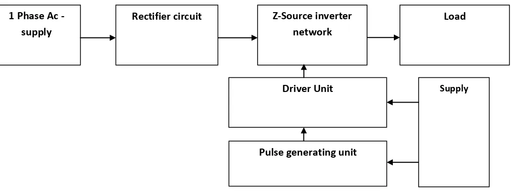
1.1BLOCK DIAGRAM FOR Z-SOURCE INVERTER FED INDUCTION
MOTOR DRIVE SYSTEM:
Fig. 1 Block diagram
Block Diagram description:
Input supply: 1 phase 230 V ac.
Rectifier: Used for converting AC TO DC Supply.
Z Source Inverter: It is a combination of two inductors and two capacitors.
Driver circuit: It consist of
Buffer IC 4050
Small ICs – MCT2E
Transistors
Darlington transistors
Capacitors
Resistors
Connections to the 3phase invertor It has two functions,
a) Amplification b) Isolation.
It can be used to amplify the 5V pulses to 12V for using transistor technology and
provide Isolation for using opto-coupler.
Pulse generating unit
Driver Unit Supply
Z-Source inverter network Rectifier circuit
1 Phase Ac -supply
53 | P a g e M8-1-1-4-2014
Pulse generator: It consist of
Bridge rectifier (1mA)
Electrolytic Capacitors
Crystal oscillator
Resistor – 33 ohm , 5Vdc
IC PIC165877A
Voltage Regulator
Reset , speed varying Buttons
Here we have used PIC microcontroller (PIC 16F877A) to make a switching signal.
MULTILEVEL INVERTER: It can output ac voltage with the same dc power supply,
which has a wider modulation index range than a traditional inverter.
Load: AC load.
1.2 IMPEDENCE SOURCE INVERTER
Fig. 2 Z-Source Inverter
The Impedance Source Inverter is used to overcome the problems in the traditional source inverters. Fig. 2 shows the main circuit of the proposed Z-source inverter based induction drive system. A voltage-type Zsource inverter is utilized, instead of the traditional voltage source inverter (VSI) or current source inverter (CSI), to feed electric energy from the dc source to the squirrel cage induction motor. To obtain the buck/boost ability, the pulse width modulation (PWM) technique should be used to control the Z-source inverter to generate shoot-through states. Unlike the Z-source inverter based ASD system with induction machines, the output currents of the Z-source inverter in the proposed induction drive system are composed of square waveforms of 120° electrical degree. Consequently, the operation principle, the modeling method and the control are all different from the Z-source inverter based ASD system with induction machines.
54 | P a g e M8-1-1-4-2014
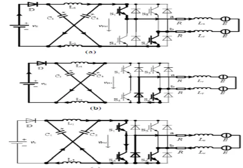
generated via shorting either any one arm or both arms in the bridge For ease of illustration, assume that the upper switches of the bridge operate in chopping modes, while the lower are used to short the bridge arms. The broad-brush lines and arrows indicate the path and direction of the currents, respectively.
Fig 3.Equivalent circuit during non-commutation stage: (a) Open (b) Active (c) Shoot – through.
From Fig.3 (a) and (b), it can be seen that only two semiconductor devices (IGBT or the anti-parallel diode) in different arms of the bridge are conducted in the non-shoot-through modes. While in the through modes, four devices are conducted when the shoot-through occurs in one phase arm, as shown in Fig.2(c).And six devices may be conducted if the shoot-through occurs in two phase arm.
55 | P a g e M8-1-1-4-2014
Fig. 4 Equivalent circuit during Phase commutation stage: (a) Open (b) Active (c) Shoot –
through state
Fig. 5 Waveform of the Gate signal
Taking the duty ratio of S1 is D1 and the duty ratio of S4 is D4, the average output voltage of the inverter is
Vo = (D1 - D4)Vs / (1 – 2D4) , Where 0 < D1, 0 < D4 < 0.5, D4 < D1 And 0 < (D1 - D4) / (1 – 2D4) < ∞
It can be seen that the output voltage can be bucked and boosted within a wide range. A straight line is used to control the shoot-through states. When the triangular waveform is lower than the straight line, the circuit turns into shoot through modes.
2. SIMULATION RESULTS:
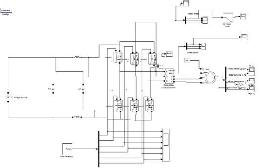
Simulations have been performed to confirm the above analysis. Fig. 6shows the circuit configuration of Z- Source fed Induction motor drive. The simulation parameters are as follows:
AC input voltage: 50 V
Z-source network: L1 = L2 = 1 mH, C1 = C2 = 1000 μF
56 | P a g e M8-1-1-4-2014
Fig.7 Inverter output 3-phase output voltage waveform
Fig.8 Inverter output3-phase current waveform
Total harmonic distortion of simulated VSI and CSI fed Induction motor drive is shown in Fig.9 and Fig.10.
57 | P a g e M8-1-1-4-2014
Fig.10 FFT analysis of VSI fed IM drive
Fig.11 shows FFT analysis of ZSI fed induction motor drive. The total harmonic distortion is found to be 11.67 % which is very less when compare to VSI and CSI fed induction motor drive.
Fig.11 FFT analysis of ZSI fed IM drive
3. HARDWARE CONFIGURATION:
Fig. 12 shows the model of the Z-source fed IM drive. The hardware parameters are as follows:
1. AC input voltage: 50 V AC
2. Z-source network: L1 = L2 =1mH, C1 = C2 = 1000 μF.
58 | P a g e M8-1-1-4-2014
3. CONCLUSION
This paper has proposed a Z – source inverter based induction motor drive. This drive system has the advantages of both PMBDCM and Z-source inverter. The system configuration, operation principle and control method have been analyzed in detail. And based on the equivalent circuits, the mathematical model has been established by state-space averaging method. Simulation results have validated the preferred features as well as the possibility of the proposed drive system. Additionally, the shortcoming of switching loss has been discussed, and a possible improvement method has been presented.
REFERENCES
[1] Fang ZhengPeng and Yi Huang Michigan, “Z-Source Inverter for Power Conditioning and Utility Interface of Renewable Energy Sources,” IEEE Trans , Vol. 23, no. 4, 2004.
[2] F. Z. Peng, “Z-source inverter,” IEEE Trans. Ind. Applicat., Vol. 39, no.2, pp.504–510, Mar./Apr. 2003.
[3] B. Justus Rabi and R. Arumugam, “Harmonics Study and Comparison of Z-source Inverter with Traditional Inverters ”, in American Journal of Applied Sciences 2 (10): 1418-1426, 2005, ISSN 1546-9239 2005 Science Publications. [4] MiaosenShen , Alan Joseph, Jin Wang, Fang Z. Peng and Donald J. Adams,“Comparison of Traditional Inverters and
Z-Source Inverter for Fuel Cell Vehicles,” IEEE Transactions, Vol. 22, NO. 4, July 2007.
[5] M. Shen, J.Wang, A. Joseph, F Z. Peng, L. M. Tolbert, and D. J. Adams,“Maximum constant boost control of the Z-source inverter,” presented at the IEEE Industry Applications Soc. Annu. Meeting, 2004.
[6] Poh Chiang Loh, Sok Wei Lim FengGao, and FredeBlaabjerg, “Three- Level Z-Source Inverters Using a Single LC Impedance Network,” IEEE Transactions on Vol. 22, NO. 2, March 2007.
[7] H.G. Sarmiento and E. Estrada, “A Voltage Sag Study in an Industry with Adjustable Speed Drives,” IEEE Industry Applications Magazine, vol. 2, pp. 16-19, 1996.
[8] A. Van Zyl, R. Spee, A. Faveluke, and S. Bhowmik, “Voltage Sag Ride-Through for Adjustable-Speed Drives with Active Rectifiers,” IEEE Transactions on Industry Applications, Vol. 34, No. 6, pp. 1270-1277, 1998.


