Role of Shunt Active Filter (SAF) for Mitigation
of Harmonics in a Non-Linear Distributed
System
Sujit Kumar Rakeshwri Agrawal
P.G. Student Assistant Professor
Department of Electrical Engineering Department of Electrical Engineering
Trinity Institute of Technology & Research, Bhopal, India Trinity Institute of Technology & Research, Bhopal, India
Abstract
Power quality is an important issue now a days. Especially in distribution network, where different loads are connected through power system network. They disturb quality of voltage and current of the distribution system like voltage sag, swell, harmonics in current and voltage, reduce power factor etc. thereby load draw excessive current for same power output with increase copper losses, reduce efficiency of system, produce excessive heat due to in nonlinear load condition produce pulsation in torque in dynamic load condition and also create disturbance in power quality of neighboring loads. For solution of these entire problems a reactive power compensation device is required. So here put up the work on Shunt Active Power Filter to improve the power quality problems. Shunt Active Power Filter to improve power factor and THD of source current in inductive and nonlinear load respectively. The Fuzzy logic controller based control scheme is used for Shunt Active Power Filter. Fuzzy logic can deal with virtually any proposition expressed in natural language. The input and output membership functions are applied with 49 fuzzy If Then weighted rule bases was designed to maintain the capacitor voltage constant by providing the required reference current amplitude.
Keywords: Quality, SAF, Fuzzy Logic, Harmonics, Non-Linear Loads
_______________________________________________________________________________________________________
I. INTRODUCTION
In the last decade several solutions have been developed in order to mitigate the mains current harmonic content. This research area has reached a major importance because the number of nonlinear loads, which are responsible for the grid current shape deformation, has drastically increased in the latest years. The most effective solutions, designed to work out this problematic, are designated by shunt active power filters – SAPF in short. Different kinds of topologies are available but the most common are the ones based on the multi-phase or single-phase half-bridge inverter with inductive decoupling [1, 2]. Classical topologies, such as those, oblige the use of switching devices rated to operate at voltages equal or above the line voltage. This represents a severe limitation when intending to build SAPFs for medium voltage grids. For this reason, classical topologies are now becoming replaced by new hybrid topologies, aiming to be more reliable and less expensive [3– 5]. These new solutions allow the reduction of the voltages of both the storage capacitors and the switching devices, to voltages lower than the mains peak voltage. This particularity is accomplished by means of introducing an extra passive filter between mains and the inverter. The most common solutions make use of series connected LC passive filters, tuned at the frequency of the mains current most significant harmonics. Given the huge boom observed in the use of electronic devices and the consequent increase of the mains current harmonic content, power grids without any kind of harmonic compensation became very sensitive to power quality problems and their related undesirable effects recalling for harmonic compensation not only at the distribution level but also at the local consumer level. The above mentioned effects are nowadays very familiar to the scientific community since they represent a serious challenge. The list bellow exemplifies only the most common:
Electromagnetic compatibility problems.
Wave shape distortion of mains voltage and current.
Extra dissipative losses.
Electromagnetic radiation.
Ruptures in balanced three-phase neutral buses.
Therefore, a great amount of effort has been made in order to minimize all those unwanted effects and their quite expensive consequences. Among others, two different important policies have been adopted to reach the previous intend: – Legislate electronic products according to their specific characteristics and use purposes, assuring that the produced harmonic content does not exceed the standard stipulated maximum.
mains current. This is true for all frequencies except for the fundamental that should not be compensated. This last principle can be accomplished by different topologies, resulting in more or less expensive, and, more or less bulky solutions that must be considered according to their specific applications.
II. SHUNT ACTIVE POWER FILTER OPERATION
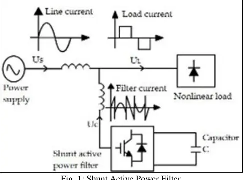
The three-phase shunt active power filter is a three-phase current controlled “voltage-source inverter” (CC-VSI) with a mid-point earthed, split capacitor in the dc bus and inductors in the ac output (It is essentially three independent single phase inverters with a common dc bus). Conventionally, a shunt APF is controlled in such a way as to inject harmonic and reactive compensation currents based on calculated reference currents.
Fig. 1: Shunt Active Power Filter
The injected currents are meant to “cancel” the harmonic and reactive currents drawn by the non-linear loads. However, the reference or desired current to be injected must be determined by extensive calculations with inherent delays, errors and slo w transient response Conventionally, the shunt type APF acts to eliminate the reactive power and harmonic currents produced by linear loads from the grid current by injecting compensating currents intended to result in sinusoidal grid current with unity power factor. This filter has been proven to be effective in compensating harmonic current sources, but it cannot properly compensate for harmonic voltage sources. Many electronic appliances, such as switch mode power supplies and electronic ballasts, are harmonic voltage sources.
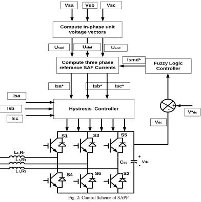
III. CONTROL SCHEME OF SHUNT ACTIVE POWER FILTER
Modeling of control scheme of SAPF system for feeding three phase load is given as follows. Three phase load currents of SAPF feeding load considered as a sinusoidal and hence their amplitude is computed as:
Vt= [2/3(Vsa2 + Vsb2 + Vsc2)]1/2 (1)
The in phase unit voltage vectors are computed by divide individual load current by their amplitude. Usad = vsa/vt; Usbd = vsb/ vt; Uscd = vsc/ vt (2)
The error in DC bus voltage of SAF Vdcer (n) at nth sampling Instant is:
Vdcer(n) = Vdc(n)* - Vdc(n) (3)
Where Vdc(n)* is the reference DC voltage and Vdc(n) is the sensed DC link voltage of the SAF. The output of fuzzy logic controller
for maintaining DC bus voltage of the SAF at the nth sampling instant is expressed as I*
cmd .Vcd(n-1)* is the amplitude of
In-phase component of the reference load voltage at (n-1)th instant. The In-phase components of the reference source current are
computed as;
I*sad=Ismd*.Usad; Isbd*=Ismd*Usbd; Iscd*=Ismd*Uscd (4)
Vsa Vsc
+ -Fuzzy Logic
Controller
Vdc
V*dc
Ismd*
Vdc S1
S2
S3 S5
S4 S6
Lf,Rf
Lf,Rf
Lf,Rf
Cdc
+
-Compute in-phase unit
voltage vectors
Compute three phase referance SAF Currents
Vsb
Usad Usbd Uscd
Isa* Isb* Isc*
Isb Hystresis Controller
Isa
Isc
+
-Fig. 2: Control Scheme of SAPF
IV. THE PROPOSED FUZZY CONTROLLER
Fuzzy logic becomes more popular due to dealing with problems that have uncertainty, vagueness, parameter variation and especially where system model is complex or not accurately defined in mathematical terms for the designed control action. The conception of the fuzzy logic introduced by Zadeh [16] is a combination of fuzzy set theory and fuzzy inference system (FIS). Elements of a fuzzy set belong to it with a certain degree, called degree of membership. The degree of membership is a result of mapping the input to certain rules using a membership function (MF). The progression which maps the specified input data to the output using fuzzy logic is known as fuzzy inference. A fuzzy inference system can be classified as: (a) fuzzification: which is the process of converting any crisp value to analogous linguistic variable based on certain MF, (b) inference engine: simulates human decision, (c) knowledge base: consists MF definitions and necessary rules like IF-THEN or it is combination of condition part with their associated rules (d) defuzzification: is the progression of transforming the fuzzy output into a crisp numerical value. In this paper main control input variable is the DC-link voltage error and output of FLC is the peak value of the reference source current. The range of operating current, normalization and de-normalization is one of the important design factors of fuzzy controller.
V. SIMULATION RESULTS
Table – 1 System Parameters
Fig. 3: Performance of System with 8Kw, Nonlinear Load without Controller
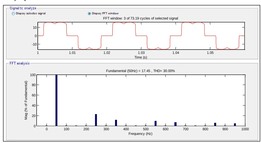
FFT Analysis for Nonlinear Load without Controller
Fig. 4: THD of Source Current for Nonlinear Load without SAPF
FFT analysis for nonlinear load are discussed in which THD (Total Harmonic Distortion) are discussed and we found that THD is very high and system is not successful for connected load. Figure shows that THD is very high without controller and it is 30℅ which is not desirable for system.
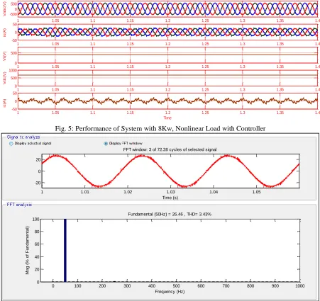
Nonlinear load with controller-This system is also connected with nonlinear load of 8 KW at 0.8s .the voltage of system maintain constant of rated 415VL_L (532.7 peak voltage). The current is increasing up to full load current at 0.8s. For this system waveform of voltage and current are given.
1 1.05 1.1 1.15 1.2 1.25 1.3 1.35 1.4
-500 0 500
1 1.05 1.1 1.15 1.2 1.25 1.3 1.35 1.4
-20 0 20
1 1.05 1.1 1.15 1.2 1.25 1.3 1.35 1.4
0 500
1 1.05 1.1 1.15 1.2 1.25 1.3 1.35 1.4
0 500
i
c
(A
) V
d
c
(V
) V
t(
V
) i
s
(A
) V
a
b
c
(V
)
1 1.05 1.1 1.15 1.2 1.25 1.3 1.35 1.4
-1 0 1
Time
1 1.01 1.02 1.03 1.04 1.05
-10 0 10
FFT window: 3 of 73.19 cycles of selected signal
Time (s)
0 100 200 300 400 500 600 700 800 900 1000
0 20 40 60 80 100
Frequency (Hz)
Fundamental (50Hz) = 17.45 , THD= 30.00%
M
a
g
(
%
o
f
Fu
n
d
a
m
e
n
ta
FFT Analysis for Nonlinear Load with Controller
FFT analysis for nonlinear load are discussed in which THD (Total Harmonic Distortion) are discussed and we found that THD is very less and system is successful for connected load. Figure shows that THD is very less with controller and it is 3.43℅ which is desirable for system. In this work system which is used for compensation of reactive power is found to be good and desirable for improvement in power quality. Results shown in the above satisfied that system is good.
Fig. 5: Performance of System with 8Kw, Nonlinear Load with Controller
Fig. 6: THD of Source Current for Nonlinear Load with SAPF
VI. CONCLUSION
In the present paper, a three-phase three-level shunt active filter with neutral-point diode clamped inverter based on fuzzy logic current controller is presented. Use of the filter is aimed at achieving the elimination of harmonics introduced by nonlinear loads. Several simulations with various nonlinear loads (AC/DC converter with R, L) under different conditions are performed using the fuzzy current controllers. The results show the superiority and effectiveness of the proposed fuzzy controller in terms of eliminating harmonics and response time, The THD is significantly reduced from 30% to 3.43% for fuzzy controller (with APF) in conformity with the IEEE standard norms. The current source for the controllers after compensation is sinusoidal. Hence, the proposed fuzzy logic current controller is an excellent candidate to control shunt active filters based on inverter topology to eliminate the harmonic currents without scarifying performance.
REFERENCES
1 1.05 1.1 1.15 1.2 1.25 1.3 1.35 1.4
-500 0 500
1 1.05 1.1 1.15 1.2 1.25 1.3 1.35 1.4
-50 0 50
1 1.05 1.1 1.15 1.2 1.25 1.3 1.35 1.4
0 500
1 1.05 1.1 1.15 1.2 1.25 1.3 1.35 1.4
0 500 1000 i c (A
) V
d
c
(V
) V
t(
V
) i
s
(A
) V
a
b
c
(V
)
1 1.05 1.1 1.15 1.2 1.25 1.3 1.35 1.4
-50 0 50
Time
1 1.01 1.02 1.03 1.04 1.05
-20 0 20
FFT window: 3 of 72.28 cycles of selected signal
Time (s)
0 100 200 300 400 500 600 700 800 900 1000
0 20 40 60 80 100 Frequency (Hz)
Fundamental (50Hz) = 26.46 , THD= 3.43%
[3] Fang Zhuo Pengbo Zhang “Study on the Influence of Supply-Voltage Fluctuation on Shunt Active Power Filter” IEEE Transactions on Power Delivery, vol.22, no.3, July2009
[4] Lee Cheulheui Seo Seonhak IEEE I999 “Analysis of the Typical Fuzzy Logic Controller Using Cell Concept” IEEE Transactions 0-7803-5406-0-1999 [5] Syamnaresh, Gupta “Shunt Active Power Filter as Front End Converter for DC Loads” Rajesh IEEE Transactions on Power Delivery, 978-1-4673-0939-
December2012
[6] Mahajan Alka, kumar Pramod “Soft computing techniques for the control of an active power filter” IEEE Transactions on Power Delivery, vol.24, no.1, January 2009
[7] Mahbub Upal “Synchronous Detection and Digital control of Shunt Active Power Filter in Power Quality Improvement” IEEE Transactions 978-1-4244-8052-4-2011
[8] Rattan Kuldeep s “Tuning of fuzzy logic controller using neural network” IEEE Transactions 0-7803-6262-4-2000
[9] Singh Bhim,Chandra Ambrish, “A new approach to three phase Active power filtering of harmonic currents in distributed system” IEEE Transactions -2012 [10] Singh B.N.,Chandra A. “Performance of sliding mode and fuzzy controller for a static synchronous series compensation IEE Conference Vol.146 No.2 March [11] Singh Bhim “Series active filter based voltage controller for an isolated asynchronous generator” IEEE Conference Bengaluru India 0-7803-3104-4 December
2012
[12] SangChul Ahn, Yong Ho Kim “Design of a Fuzzy Logic Controller Mod Controller” IEEE Transactions 0-7803-3104-4 January 1996
[13] Zeng F.P.,Tan G.H “Novel single phase five level voltage source inverter active power filter” IET Power Electron Delivery, vol.3, no.1, Aug 2010 [14] M. S. Janko Nastran, Rafael Cajhen and P. Jereb, “Active power filter for nonlinear ac loads,” IEEE Trans. on Power Electronics, vol. 9, pp. 92–96. [15] M. George and K. P. Basu, “Three-phase shunt active power filter,” American Journal of Applied Sciences, vol. 5 (8), pp. 909–916-2008.
[16] J. M. Joo Afonso, Carlos Couto, “Active filters with control based on the p-q theory,” IEEE Industrial Electronics Society Newsletter, vol. 47, no. 3, ISSN: 0746-1240-2000.
[17] M. A. E. H. Watanabe, R. M. Stephan, “New concepts of instantaneous active and reactive powers in electrical systems with generic loads,” IEEE Trans. on Power Delivery, vol. 8, no. 2, pp. 697–703.
[18] E. H. W. M. Aredes, “New control algorithms for series and shunt three phase four-wire active power filters IEEE Trans. on Power Delivery, vol. 10, no. 3, pp. 1649–1656.
[19] E. W. J. M. Joo Afonso, Maurcio Aredes, “Shunt active filter for power quality improvement,” International Conference UIE 2000 – Electricity for a Sustainable Urban Development Lisboa, Nov. 2000.
[20] H.Akagi, “New Trens in Active Filters for Power conditioning”. IEEE Transactions Ind Applicat., Vol.32, No.6, pp.1312-1322, Nov /Dec.1995. [21] Bhim Singh, Kamal Al-Haddad, Ambrish Chandra, “A review of active filters for power quality improvement”. IEEE Trans on I.E. Vol.46, No.5,
pp.960-971. October, 1999. 931
[22] M.EI-Habrouk, M.K.Darwish,P.Mehta.“Active power filters: a review”. IEE Proc. Electr. Power. Appl., Vol.147, No.5, pp.403-413, Sept. 2000.
[23] S. Buso, L. Malesani, and P. Mattavelli, “Comparison of current control techniques for active filters applications”. IEEE Trans. Ind. Electron, vol. 45, pp. 722–729, Oct. 1998.
[24] P. Agarwal, A. Chandra, K. Al-Haddad, and K. Srinivasan, “Active power filter to compensate only customer generated harmonics simulation study,” in Proc. 11th Nat. Power Syst. Conf., Bangalore, India, Dec. 20–22, 2000, pp. 614–619.