ISSN : 2581-7175 ©IJSRED: All Rights are Reserved Page 503
Design and Implementation of Computer Interfaced Voice
Activated Switch using Speech Recognition Technology
Nwankwo P. N.*, Orji M. N.**
*(Department of Computer Engineering; Federal Polytechnic Oko, Anambra State, Nigeria Email: [email protected])
** (Department of Computer Science; Federal Polytechnic Oko, Anambra State, Nigeria Email:[email protected])
---
************************
---Abstract:
This paper presents the design and implementation of “Computer Interfaced Voice activated switch” using speech recognition technology. Computer (PC) based electrical appliances control is useful for industrial applications, home automation, and supervisory control applications. This project gives exact concept of interfacing high voltage electrical devices to a computer system. The project involves speech activation or deactivation of electrical load using voice command or manual method. This is achieved by developing a speech application using visual basic 6.0 and then linking it to a program that drives the parallel port of the computer. Two stages were implemented in the design of this system; the hardware and software design stages. All stages were carried out carefully, adhering strictly to the design specifications. This proved useful as the results obtained after construction and testing were extremely satisfactory because the system was able to switch the connected loads ON and OFF using voice command and manual control method. This is a secure and reliable system which can be used in homes, industries, churches, offices, etc. The system involves the AT89C52 microcontroller, Max232 (IC), actuators (relays), and other active and passive electronic components connected together to form the hardware unit. The AT89C52 microcontroller was used to store all the machine codes of the system. The computer was used to establish an interface or a communication link with the microcontroller. The communication link used in this project was the parallel port. The computer sends the corresponding signal to the microcontroller anytime a voice instruction/manual command is received, then the microcontroller executes the instruction by switching ON/OFF the corresponding load connected to it through the actuator. Satisfactory results based on the design specification were achieved after construction.
Keywords: Voice Activated Switch (VAS), Graphic User Interface (GUI), Computer Interface (CI), Parallel Port (PP), Speech Recognition Technology (SRT), Visual Basic (VB)
---
************************
---I. INTRODUCTION
Home automation is not a new concept in today‘s world, it is used to provide convenience for user to remotely control and monitor home appliances and processes [1]. With the recent advancements in personal computers (PC), internet, mobile phone, wireless and speech
recognition technology, it makes it easy and simple for a user to remotely access and controls home appliances and processes. A lot of research has been done and many solutions have been proposed to remotely control home appliances, and voice recognition technology is one of such control systems.
ISSN : 2581-7175 ©IJSRED: All Rights are Reserved Page 504 A. Statement of the Problem
1. In the radioactive process, manual switching poses great health hazards to the operator due to the side effects of exposure to the radioactive elements.
2. Manual switching is an uphill task for the physically challenged persons and the aged due to movement constraints.
3. Sometimes, we are victims of electric shocks from our devices when we try to switch them ON/OFF due to leakage currents from the electric switches.
B. Significance of Project
Implementing this system will be of great benefit to our ever demanding and developing society. Some of these benefits include;
1. Accidental switching of devices will be reduced to minimum in our industries and homes.
2. Walking from point to point to switch ON/OFF appliances will be reduced. 3. It is cost effective compared to other
automated systems.
4. Switching can be done from a far distance to safeguard people during hazardous industrial control.
5. Our industries and homes will become friendly to physically challenged persons. 6. Explore and expand the capability and the
compatibility of the computer system in controlling physical processes.
C. Aim of the Project
The aim of our system is to build a perfect home automated system that can switch ON/OFF three electrical devices: one electric bulb, and two sockets using voice command or manual method.
D. Objectives of the Project
1. Communicate with a microcontroller via a PC parallel port using VB 6.0.
2. Control home appliances using voice recognition technology or manual method.
3. Demonstrate how to use the computer system and the microcontroller to control home appliances and industrial processes.
4. Demonstrate the need and importance of adopting voice recognition technology in home automation and hazardous industrial control. E. Methodology
The designed system “Voice Activated Switch” is all about automating real life processes using speech recognition technology. It involves developing a speech application using visual basic 6.0 and then linking it to a program that drives the parallel port of the computer. Visual basic 6.0 has some objects that enable one to develop voice applications like Microsoft direct text to speech, direct speech synthesis, voice dilation, and voice command. These are some of the applications developed by Microsoft and incorporated into visual basic 6.0 components library which must be invoked into the object window and subsequently included into the form before their properties and settings will be configured for use.
For visual basic 6.0 to access the Microsoft Voice applications, a Speech engine DLL (dynamic link library) must be deployed in the system 32 of the computer. The devices to be controlled are interfaced to the computer through the parallel port. Based on the fact that VB 6.0 is an event driven program, the events of a voice command must be registered and listed as a menu item in the program.
The particular voice command to actuate a particular device must be registered, so that whenever the command is spoken the sound goes into the computer through the microphone and the right event will be generated. The VB 6.0 codes handle the events and their various cases. The desired code to actuate a particular device will be written under its case.
ISSN : 2581-7175 ©IJSRED: All Rights are Reserved Page 505 transistor. This is passed through a buffer to
strengthen/boost the voltage signal. The transistor is used to activate or deactivate (ON/OFF) the
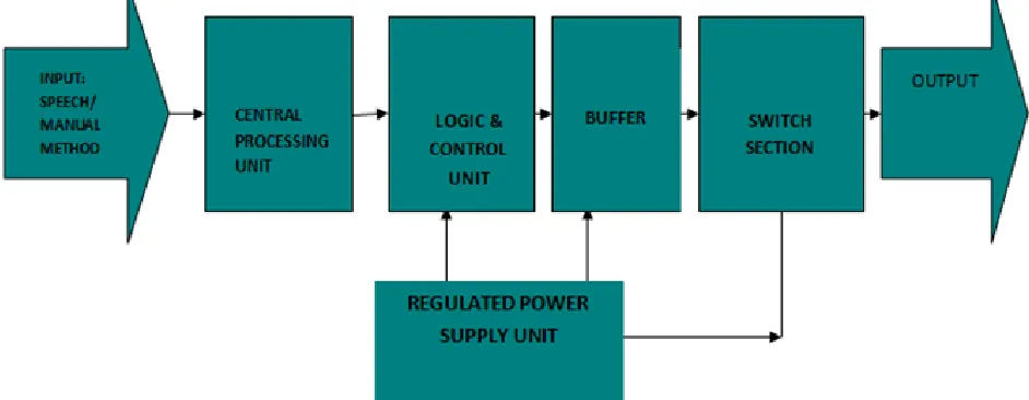
relay depending on the command/instruction. The block diagram of the Computer Interfaced Voice Activated switch is shown in fig.1 below.
Fig. 1: The Block Diagram of the Computer Interfaced Voice Activated Switch
II CONCEPTS OF COMPUTER INTERFACING
Computer interfacing is the art of connecting computers and peripherals. An interface device is a hardware component or system of components that allows a human being to interact with a computer, a telephone system, or other electronic information
system [2].
A. The Computer External Bus
The computer bus is a group of conductor lines that allows the memory, Central processing unit (CPU) and the I/O devices to exchange data. External devices are connected to the computer through an I/O interface called a port. A port is a hardware that allows data to be shared, enter or exit a computer, network node or a communication device. There are basically two types of ports, the parallel and serial port; but in this project, the
parallel port was used.
B. The Parallel Port
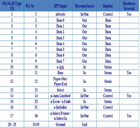
The Parallel Port is the most commonly used port for interfacing homemade projects. This port will allow the input of up to 9 bits or the output of 12 bits at any one given time, thus requiring minimal external circuitry to implement many simpler tasks. The port is composed of 4 control lines, 5 status lines and 8 data lines. It's found commonly at the back of the PC as a D-Type25 Pin female connector. There may also be a D-Type 25 pin male connector. This will be a serial RS-232 port and thus, is a totally incompatible port [3]. The primary use of parallel ports is to connect printers to computers and specially designed for that. See table 1 below for the pin assignment of the D-type 25 pin.
TABLE 1:
ISSN : 2581-7175 ©IJSRED: All Rights are Reserved Page 506 Visual basic 6.0 cannot access the computer
parallel port directly unlike serial port. Some DLL (Dynamic Link Libraries) that was built in embedded C must have been deployed in the system32 (the system registry) first. And a module that can reference to this DLL must have been declared in the program. This module contains some functions like VB-in and VB-out, which VB 6.0 uses to read from and write to the port respectively.
They are often used to connect devices or receive large amount of data such as printers. They transfer 8 bits (one byte) of a time using a cable with 8 data line-they’re also known as DB 25 since they have 25 female pin connector.
The lines in DB 25 connector are divided into; Data line (data bus) = 8 lines, Control lines = 4 lines, and Status line = 5 lines. Each section is accessed by its own address and will act independently from the rest. This is almost as if they were different ports. The addresses show in table 2 below.
TABLE 2:
ADDRESS OF THE DIFFERENT PORT LINES
The Data register has 8 non-inverted lines and is used to write to the parallel port i.e. for outputting. It has port address of 888 or 378 hex. The control register has 4 lines of which 3 of the lines are inverted and is to control peripheral devices and also for outputting [4]. It has port address of 890 or 39A hex. The status register is has 5 lines of which only one is inverted it is use to read from the parallel port i.e. for inputting .It has port address of 889 or 379 hex.
Data is transferred over data lines while the control lines are used to control the peripheral. The peripheral returns status signals back to the computer through status lines.
Fig. 2 below shows the DB-25 connector.
Fig. 2: The DB-25 connector
C. Concepts of Libraries
ISSN : 2581-7175 ©IJSRED: All Rights are Reserved Page 507 other through the process known as linking, which
is typically done by a linker. The main reason for libraries are to prevent the redesign of software each time a function is needed in a task and also for resource sharing. There are actually two types of libraries: dynamic and static library.
1. Static Library
In computer science, a static library or statically-linked library is a set of routines, external functions and variables which are resolved in a
caller at compile-time and copied into a target application by a compiler, linker, or binder, producing an object file and a stand-alone executable [6]. This executable and the process of compiling it are both known as a static build of the program. Historically, libraries could only be static. Static libraries are either merged with other static libraries and object files during building/linking to form a single executable, or they may be loaded at run-time into the address space of the loaded executable at a static memory offset determined at compile-time/link-time.
2. Dynamically Linked Libraries
Dynamic linking means that the subroutines of a library are loaded into an application program at runtime, rather than being linked in at compile time and remain as separate files on the disk. Only a minimal amount of work is done at compile time by the linker; it only records what library routines the program needs and the index names or numbers of the routines in the library. The majority of the work of linking is done at the time the application is loaded (load time) or during execution (runtime). The necessary linking code, called a loader, is actually part of the underlying operating system.
III. SYSTEM IMPLEMENTATION
A. Hardware Implementation
ISSN : 2581-7175 ©IJSRED: All Rights are Reserved Page 508
DB 25 connector
1 2 V 1 2 V 1 2 V C 1 ? C 2 ? P A R E L L E L P O R T M ic ro c o n tr o lle r u n it OCTA BUFFER 74244 P 1 .0 P 1 .1 P 1 .2 P 2 .0 P 2 .1 P 2 .2 1 8 1 9 2 0 Q 3 Q
2 Q1
D 1 D 2 D 3 R 1 1 0 0 ? R 2 1 0 0 ? R 3 1 0 0 ? L ig h t2 L iv e L ig h t1 L ig h t3 L iv e L iv e V C C
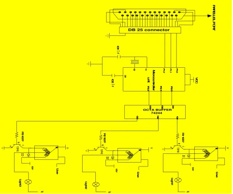
Fig. 3: Circuit diagram of the Computer Interfaced Voice Activated Switch
B. The AT89C52 Microcontroller
The microcontroller is used to store the assembly language codes that reads the communication port of the computer and controls the home appliances via the actuators (relays). The AT89C52 is a low-power, high-performance CMOS 8-bit microcomputer with 8K bytes of Flash programmable and erasable read only memory (PEROM). The device is manufactured using Atmel’s high-density non-volatile memory technology and is compatible with the
ISSN : 2581-7175 ©IJSRED: All Rights are Reserved Page 509 signifying the instruction about to be carried out,
decodes the instruction, and carries it out according to the steps required [8].
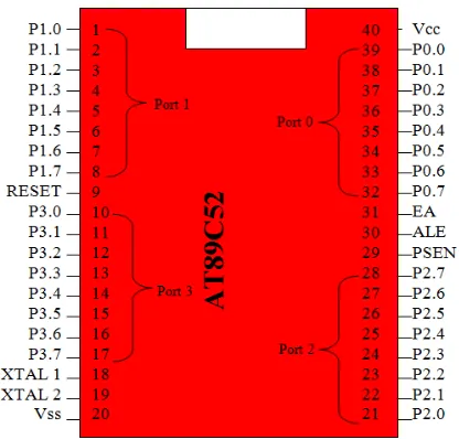
Fig. 4 below shows the pin configuration of the AT89c52 microcontroller.
Fig 4. The pin configuration of the AT89C52 microcontroller
C. The Regulated Power Supply Unit (RPSU):
Electronic components require a steady dc power supply. Thus; a regulated dc power supply unit was built to this effect, to provide the power requirements of the system. The RPSU is made up of the following sections:
Transformer (Transformation): This section scales down/reduces the supply voltage to 12v Ac (from 220vAc to I2Ac). value close enough to the desired DC value (12V). Rectifier (Rectification): This
section converts the scaled down AC signal to a varying DC signal (12Dc). Capacitor (Filtration): This section removes ripples from the rectified signal to give a fairly constant dc value. Regulator (Regulation): This section fixes a positive Dc output voltage (+5V) by eliminating ripples. Fig. 5 below shows the circuit diagram of the +5v regulated power supply.
Fig. 5: Circuit Diagram of the +5v Regulated Power Supply
D. Microcontroller, Buffer, and Relay Interface
Fig. 6: Microcontroller, Buffer, and Relay Interface
Fig. 6 above shows how the buffer and the relays are interfaced with the microcontroller. The buffer is used to strengthen (boost) the signal from the microcontroller. The signal is then used to drive the actuators (relays) which are used to control the home appliances by switching between normally op (NO) and normally close (NC) of the relay. Note: our system can control three home appliances, thus; the three relays.
IV. SOFTWARE IMPLEMENTATION AND SYSTEM FLOWCHAT
ISSN : 2581-7175 ©IJSRED: All Rights are Reserved Page 510 interface (GUI) for operators. It also entails the
assembly language code programmed into the microcontroller for effective control of the home appliances.
1. Speech Engine (DLL):
Speech automation is all about automating real life devices with the aid of speech. This is achieved by registering some command in the voice command menu of the program. Based on the fact that VB 6.0 is an event driven
programming language the event of the registered command will be fired whenever the event listener hears any sound that is the same with registered speech command. The corresponding task will be coded under the voice Recognized sub procedure. Meanwhile before VB 6.0 can access speech some speech Engine DLL must have been deployed in the system directory. VB 6.0 uses the Ms Voice Command object to access speech, while it uses Ms Direct Text-To-Speech object to convert text to speech. Fig. 7 below shows the two speech objects.
ISSN : 2581-7175 ©IJSRED: All Rights are Reserved Page 511 2. Graphical User Interface (GUI)
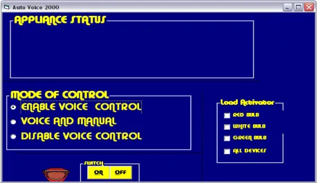
Fig. 8. Voice Activated Switch Graphical User Interface
The application package for the voice activated switch has a graphical user interface (GUI) as shown in fig. 8 above. The Control of the devices connected to this system is done by speaking the appropriate word stored in the database of the computer system like (bulb 1 come on, or fan go off) or by simply clicking the required ON/OFF button associated with the loads. The software design provides two different types of control to the load. They are; Mode 1 control and mode 2 control
1. Mode 1 control
This type of control provides only a simple ON/OFF control of the load. The load is put ON or OFF by simply clicking the ON or OFF command button respectively.
2. Mode 2 control
Mode 2 allows the control of the load from both a manual switch and the voice activated switch. It has the enable voice control, voice and manual, and the disable voice control command buttons. The enable voice control command button is used to activate voice control of the load. The disable manual control button is used to disable the manual switching of the load.
3. Visual Basic Code of the System
ISSN : 2581-7175 ©IJSRED: All Rights are Reserved Page 512
Fig.9: Complete Visual Basic Code of the Computer Interfaced Voice Activated Switch.
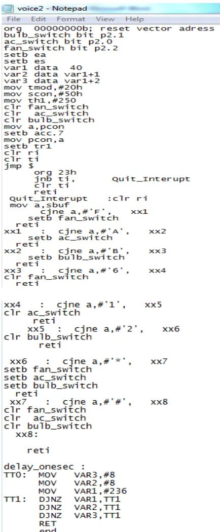
4. Assembly Language Program of the System
ISSN : 2581-7175 ©IJSRED: All Rights are Reserved Page 513
www.ijsred.com
ISSN : 2581-7175 ©IJSRED: All Rights are Reserved Page 514 5. System Flowchart
Fig11. Flow Chat of the Computer Interfaced Voice Activated Switch START
INITIALIZE PROGRAM
CHOOSE CONTROL METHOD
IS IT MANUAL?
TICK DEVICE CHECK BOX
CLICK THE APPROPRIATE BUTTON
IS DEVICE OFF?
PUT OFF DEVICE
STOP
SPEAK APPROPRIATE COMMAND
PUT ON DEVICE YES
NO
YES
www.ijsred.com
ISSN : 2581-7175 ©IJSRED: All Rights are Reserved Page 515 V. CONCLUSION
After the construction and testing of the system, the following results were achieved:
• Switching of loads ON and OFF using the voice commands.
• Switching of loads ON and OFF using the manual control.
The design and implementation of computer interfaced “Voice Activated Switch” using speech recognition technology and manual method had been proven to be a reasonable advancement in speech recognition technology and control system technology. The work done here is original and has not been published. The computer interface has expanded the flexibility of the multi-functional Microcontroller. This is a major breakthrough in speech recognition and technological advancement in general.
We therefore conclude that this system switches reliably using manual and voice methods. It is a secure and reliable device which can excel in this day and age.
REFERENCES:
[1] Amrutha S, Aravind S, Ansu Mathew, Swathy Sugathan, Rajasree R, Priyalakshmi S, (2015), “Voice Controlled Smart Home”, International Journal of Emerging Technology and Advanced Engineering”, Volume 5, Issue 1.
[2] R. P. Jain, (1998), Modern Digital Electronics, Tata Mc Graw- Hill Publishing Company Ltd, New Delhi 110008, Second Edition, pp 97 [3] http://geekgoing.blogspot.com/2011/05/parallel-port-basics.html [4] M.A.A. Mashud, M. R. Hossain, Mustari Zaman, M.A. Razzaque., (2014) “PC Guided Automatic Vehicle System”, International Journal on Cybernetics & Informatics (IJCI) Vol. 3, No. 6, December 2014. [5] Gray A.B. (2001): Learning Visual Basic, Published by Garret and Garret house.
[6] Hart.K.A. Johnson .W.A. (2005.): Windows System Programming, Third Edition Published by Morgan Kaufmann Publishers.
[7] Nwankwo, P. N, (2017), “8051/8951 Microcontroller: Instruction formats, Assembly Language, and Hardware Interfacing”, Awka, Benzero Grapfix, pg 80-83.