International Journal of Research Publications
Performance Analysis Ionic Thruster and Grid Configuration Ei Ei Khainga, Kyaw Kyaw Shweb aDepartment of Space Systems Engineering, Myanmar Aerospace Engineering University
Myanmar
b
Department of Propulsion and Flight Vehicles,, Myanmar Aerospace Engineering University Myanmar
Abstract Electric propulsion is a technology aimed at achieving thrust with high exhaust velocities, which results in a reduction in the amount of propellant required for a given space mission or application compared to other conventional propulsion methods. Reduced propellant mass can significantly decrease the launch mass of a spacecraft or satellite, leading to lower costs from the use of smaller launch vehicles to deliver a desired mass into a given orbit or to a deep-space target. In general, electric propulsion (EP) encompasses any propulsion technology in which electricity used to increase the propellant exhaust velocity. Naturally, spacecraft designers are then concerned with providing the electrical power that the thruster requires to produce a given thrust, as well as with dissipating the thermal power that the thruster generates as waste heat. Total voltage across the screen and accelerator grid take 1-2 kV and screen grid voltage is 200 V. Total voltage and ion current density applied in finding the distance between screen grid and accelerator grid. Parameters of the grid are to get thruster parameters such as thrust force, exhaust velocity, specific impulse and thruster efficiency.
© 2018 Published by IJRP.ORG. Selection and/or peer-review under responsibility of International Journal of Research Publications (IJRP.ORG)
Keywords: Electric propulsion; propellant; space mission; accelerator grid; thruster efficiency
International Journal of Research Publications
Volume-21, Issue-1,January 2019
Accepted and Published Manuscript
Performance Analysis Ionic Thruster and Grid Configuration
Ei Ei Khaing
PII : Ei Ei Khaing.10021112019500
DOI: 10021112019500
Web: http://ijrp.org/paper-detail/501
To appear in: International Journal of Research Publication (IJRP.ORG)
Received date: 17 Jan 2019
Accepted date: 05 Feb 2019
Published date: 07 Feb 2019
Please cite this article as: Ei Ei Khaing , Performance Analysis Ionic Thruster and Grid Configuration ,
International Journal of Research Publication (Volume: 21, Issue: 1), http://ijrp.org/paper-detail/501
International Journal of Research Publications
Performance Analysis Ionic Thruster and Grid Configuration
Ei Ei Khaing
a, Kyaw Kyaw Shwe
baDepartment of Space Systems Engineering, Myanmar Aerospace Engineering University
Myanmar
bDepartment of Propulsion and Flight Vehicles,, Myanmar Aerospace Engineering University
Myanmar
Abstract
Electric propulsion is a technology aimed at achieving thrust with high exhaust velocities, which results in a reduction in the amount of propellant required for a given space mission or application compared to other conventional propulsion methods. Reduced propellant mass can significantly decrease the launch mass of a spacecraft or satellite, leading to lower costs from the use of smaller launch vehicles to deliver a desired mass into a given orbit or to a deep-space target. In general, electric propulsion (EP) encompasses any propulsion technology in which electricity used to increase the propellant exhaust velocity. Naturally, spacecraft designers are then concerned with providing the electrical power that the thruster requires to produce a given thrust, as well as with dissipating the thermal power that the thruster generates as waste heat. Total voltage across the screen and accelerator grid take 1-2 kV and screen grid voltage is 200 V. Total voltage and ion current density applied in finding the distance between screen grid and accelerator grid. Parameters of the grid are to get thruster parameters such as thrust force, exhaust velocity, specific impulse and thruster efficiency.
© 2018 Published by IJRP.ORG. Selection and/or peer-review under responsibility of International Journal of Research Publications (IJRP.ORG)
1.Introduction
Ionic thrusters generally use heavy inert gases such as xenon as the propellant. Other propellant materials, such as argon and krypton, have investigated in the past. Xenon is generally preferable because it is not hazardous to handle and process, it does not condense on spacecraft components that are above cryogenic temperatures, its large mass compared to other inert gases generates higher thrust for a given input power, and it is easily stored at high densities and low tank mass fractions. Therefore, the focus will be on xenon as the propellant in ionic thrusters, although performance with other propellants can examine using the basic information provided here.
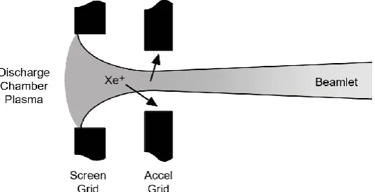
Ion engine consists of a cylindrical structure delimited by a set of two (or three, depending on the thruster) precisely placed grids at the end side. Such grids have a matrix of tailored holes in order to extract the ion beam. The first grid called screen grid, whereas the second one referred to as the accelerator grid. When a third grid used, it known as decelerator grid. The other side of the cylinder bounded by a flat plate. The volume delimited by this structure (cylinder, grids and flat plate) refer to as the discharge chamber or ionization chamber.
The design of the grids is critical to the ion thruster operation and is a trade between performance, life, and size. Since ion thrusters need to operate for years in most applications, life is often a major design driver. However, performance and size are always important in order to satisfy the mission requirements for thrust and specific impulse (Isp) and to provide a thruster size and shape that fits onto the spacecraft.
The life time of ionic thrusters is based on the accelerator grid erosion from ion sputtering. The erosion geometry is naturally divided into two regions. The first region is barrel erosion and the second region is caused by charge ions generated downstream of the accelerator grid.
Accelerator grid structure failure is the bridge between the holes has fractured by erosion, whole the structure was destroyed and cannot extract ion beam any normal. Structure damage caused by the accelerator grid ion sputter erosion involves two mechanisms.
(1) Beam ions that energy equivalent to total acceleration voltage sputter on the upstream surface of accelerator grid.
(2) Charge-exchange (CEX) ions that energy equivalent to accelerator grid voltage sputter on the downstream surface of accelerator grid that made pit and groove erosion.
The first type erosion mechanism can avoided by a reasonable geometry design and the second type erosion mechanism is the main factor that can lead to structure failure of accelerator grid.
1.1.Grid Configuration
To accelerate ions, a potential difference must be established between the plasma produced inside the thruster plasma generator and the ambient space plasma for two singly charged ion current densities at an acceleration voltage 1000-2000V.
For xenon, the characteristic aperture diameter at this voltage is on the order of 2 to 5 mm and will decrease if the applied voltage is reduced or the current in the aperture is increased. The ion current obtainable from each grid aperture is then limited by space charge. Multiple apertures must be used to obtain higher beam currents from the ion engine to increase the thrust.
sputtering. In practice, the grids are made of refractory metals or carbon-based materials, and the apertures are close-packed in a hexagonal structure to produce a high transparency to the ions from the plasma generator.
The high-voltage bias supply (called the screen supply) is normally connected between the anode and the common of the system, which is usually connected to the neutralizer cathode (called “neutralizer common”) that provides electrons to neutralize the beam. Positive ions born in the discharge chamber at high positive voltage accelerated out of the thruster. The accelerator grid is biased negative relative to the neutralizer common to prevent the very mobile electrons in the beam plasma from back-streaming into the thruster, which produces localized heating in the discharge chamber by energetic electron bombardment, and ultimately overloads the screen supply if the back-streaming current becomes large. The ion beam is current neutralized and quasi-neutral (nearly equal ion and electron densities) by the electrons extracted from the neutralizer cathode.
A three-grid accelerator system, where a final grid called the “decelerator grid” placed downstream of the accelerator grid. This grid shields the accelerator grid from ion bombardment by charge exchanged ions produced in the beam back-flowing toward the thruster, and eliminates the downstream “pits-and-grooves erosion”. Three-grid systems then potentially have longer accelerator grid life than two grid systems and generate less sputtered material into the plume that can deposit on the spacecraft. These benefits offset by the increased complexity of including the third grid.
In actual design, the diameter of each accelerator grid aperture is minimized to retain unionized neutral gas in the plasma generator, and the screen grid transparency is maximized so that that the grids extract the maximum possible number of ions from the plasma.
In the two- or three-grid configurations, the geometry of the grid apertures and gaps intended to eliminate or at least minimize direct impingement by beam ions on the most negative potential electrode in the system, namely, the accelerator grid. This is required to minimize sputtering of the grid by the high-energy beam ions. Sputter erosion of the screen grid then becomes an issue only at high discharge voltages or due to the production of high-energy ions in the hollow cathode region that can bombard the screen grid. Likewise, the decelerator grid is biased near the beam plasma potential and back-flowing ions produced in the beam by charge exchange impact with very low energy, which causes little or no sputtering. For two grid systems, the back-flowing ions bombard the accelerator grid with essentially the grid bias voltage. This can cause significant sputtering of the downstream face of the accelerator grid and may determine the grid life. Ions generated between the grids by either charge exchange with unionized neutral gas escaping the plasma generator or by ionization from the most energetic back-streaming electrons do strike the accelerator grid and erode it. Charge exchange ion erosion of the accelerator grid ultimately limits the grid life.
2.Design Methodology
2.1.Ion Accelerator Basics
The thruster ion optics assembly serves three main purposes: (1) Extract ions from the discharge chamber
(2) Accelerate ions to generate thrust (3) Prevent electron back-streaming
not available to become part of the beam. The goal for screen grid design is to maximize the grid transparency to ions by minimizing the screen thickness and the webbing between screen grid holes to that required for structural rigidity. The maximum beam current density is limited by the ion space charge in the gap between the screen and accelerator grids. The maximum beam current density is,
3
2
4
2
2
9
V
e
o
T
J
max
M d
(1)Where = the total voltage across the sheath between the two grids d = the distance between screen and accelerator grid
M = mass of a xenon atom e = electron charge (1.602176487
= permittivity of free space (8.8542 F/m)
Fig.1. Showing enlarged section of the double grid for an electron bombardment of ion thruster
The ion velocity leaving the accelerator is
2
eV
b
v
i
M
(2)Where, eVb= the net beam energy
The effective electric field in the acceleration gap is
V
T
E
L
e
(3)Where, = the total voltage across the accelerator gap (the sum of the screen and accelerator grids) = sheath thickness
V
T
V
s
V
acc
(4)Where, = screen grid voltage
Beams of ions flow through grid holes
= accelerator grid voltage
The maximum Isp that is achievable is limited by the voltage that can be applied to the grids to extract a given
current density before electrical breakdown or electron back-streaming occurs. The thrust provided by the thruster computed, by using this equation is
6.18 10
12
2
(
)
2
D
aperture
F
t
V
acc
N
aperture
d
(5)Where = aperture diameter = number of aperture The exhaust velocity of the thruster is
13800
V
acc
V
exhaust
M
(6)Where, = accelerator grid voltage
2.2. Grid Expansion and Alignment
A significant issue in ion thrusters that utilize refractory metal grids is thermal expansion of the grids during thruster operation changing the acceleration gap dimension between the screen and accelerator grids. This will directly affect the ion trajectories and the perveance of the ion optics. Since the screen grid heated by direct contact with the discharge plasma and is usually dished outwards and designed with a minimum thickness to increase the effective transparency, the screen grid expansion is usually larger than the accelerator grid and the gap tends to decrease as the thruster heats up. For ion thrusters with refractory metal grids designed with concave grid curvature, the screen grid expands away from the accelerator grid and the perveance decreases, as the gap gets larger. In addition, concave grids have a smaller discharge chamber volume for a given thruster size, which adversely affects the discharge loss.
Another significant grid issue is alignment of the grid apertures. The ion trajectories assumed perfect alignment of the screen and accel grid apertures, and the resultant trajectories are then axis-symmetric along the aperture centerline. Displacement of the accel grid aperture relative to the screen grid centerline causes an off-axis deflection of the ion trajectories, commonly called beam steering.
Mechanical misalignment of the grids due to manufacturing tolerances or thermal deformation can also produce aperture displacement and unintended beamlet steering. For this reason, precise alignment of the grid apertures and grid support mechanisms that minimize non-uniform thermal deformation are generally required to provide stable ion optics performance with minimal beam divergence.
2.3. Ionic Thruster Accelerator Grid Life
surface of the accelerator grid aperture, which results in enlargement of the aperture barrel. As the barrel diameter increases, the grid must be biased more and more negatively in order to establish the minimum potential required in the aperture to prevent neutralizer electrons from back-streaming into the discharge chamber. Thruster failure occurs when, at its maximum voltage, the accelerator grid power supply is unable to stop electron back-streaming.
The second region of grid erosion is caused by charge exchange ions generated downstream of the accelerator. Since the beamlets are long and thin, inside each beamlet the radial electric forces dominate and expel the slow, charge-exchange ions into the gaps between the beamlets. Charge exchange ions generated in the region before the beamlets merge to form a continuous ion density attracted back to the accelerator grid by its large negative potential. On impact, these ions sputter away material from the downstream surface of the accelerator grid. Sputter erosion by these back-streaming ions results in a hexagonal “pits-and-grooves” erosion pattern on the downstream grid surface, which can lead to structural failure of the grids if the erosion penetrates all the way through the grid. Erosion of the accelerator grid aperture edge by back-streaming ions can also effectively enlarge the accelerator grid aperture diameter, leading to the onset of electron back streaming.
Fig. 2. Ions that cause barrel erosion generated by charge exchange upstream and within the accelerator grid aperture
Fig.3. Ions that cause pits and grooves erosion generated between the downstream surfaces of the accelerator grid
2.4.Barrel Erosion
and the accelerator grid thickness. The number of grid apertures is approximately the grid open area divided by the area per aperture.
2
2
f
a
r
grid
N
apertue
r
aperture
(7)Where,
= open area fraction
The number of apertures can be from hundreds to thousands and total force depend on it.
2.5.Calculation of Grid Parameters,
Assuming,
V
1000 2000
V
t
V
200
V
screen
V
800 1800
V
acc
D
1 5
mm
aperture
D
15 30
cm
grid
The thrust range of ionic thruster is 25-250mN.The calculated grid parameters are used to get the maximum thrust force and exhaust velocity for ionic thruster of communication satellites.
For xenon propellant,
Total voltage across the accelerator gap,
V
1300
V
t
V
200
V
screen
V
1100
V
acc
V
1100
V
acc
(for accelerator grid)
r
gri
d
14.5
cm
1.45 10
1
m
r
aperture
1.25
cm
1.25 10
3
m
2
2
f
a
r
grid
N
apertue
r
aperture
1 2
0.24
(1.45 10
)
3 2
(1.25 10
)
3229.44
J
i
139 /
A m
2
Proton mass
1.6726 10
27
kg
Molecular mass
=131.293AMU
ion massproton mass
molecular mass
1.6726 10
27
131.293
2.196 10
25
kg
Electron charge,
e
1.6022 10
19
C
1
3
2
2
4
2
9
V
e
o T
d
J
i
m
i
3
1
12
2
19
4 8.8542 10
1300
2 1.6022 10
2
(
)
25
9 139
2.196 10
0.00127m
1.27 10
3
mm
D
2.5 10
3
m
aperture
Force,2
12
2
6.18 10
D
aperture
F
V
acc
d
3
2.5 10
12
2
2
6.18 10
1300
(
)
3
1.27 10
2.916 10
5
N
The thrust provided by the thruster,
F
F N
2.916 10
5
3229.4
0.094N
94mN
13800
V
acc
V
exhaust
M
13800
1100
131.293
39.944
km s
/
For Krypton,
N
3229.44
aperture
d
0.00147
m
1.47 10
3
mm
F
2.2 10
5
N
F
0.0698
N
69.8
mN
t
V =49998.687m / s= 49.999km / s
ex
For Argon,
N
3229.44
aperture
d
0.00179m
1.79 10
3
mm
F
1.46 10
5N
F
0.0470
N
47
mN
t
V
72414.8
9
m s
/
ex
72.415km / s
The largest diameter of the grid and the smallest diameter of aperture use to achieve the largest number of aperture. The largest number of aperture decide the value of thrust. Exhaust velocity change depending on the voltage of accelerator and the molecular mass of the gas. If the dimension of the gap distance between grids is large, ions will miss the aperture and rapidly erode the surface of grid. The smaller gap distance will increase the temperature of grid and cause thermal deformation.
2.6.Definition and Ionic Thruster Parameters
2.6.1.Thrust
F
mv
T
ex
(8)Where,
= total thrust force
= propellant mass flow rate = exhaust velocity
Propellant mass flow rate,
F
T
m
v
ex
(9)2.6.2.Kinetic Power
The kinetic power of an object is the energy that it possesses due to its motion. It is defined as the work needed to accelerate a body of a given mass from rest to its stated velocity. Having gained this kinetic energy unless its speed changes. The kinetic thrust power of the beam, called the jet power, defined as
1
2
2
P
je
t
m
v
e
x
(10)Where,
= kinetic power
= propellant mass flow rate = exhaust velocity
2.6.3.Input power
The electrical power input, Pin, to the thruster in watts, is usually the product of the electrical current and
all associated voltages (hence the -sign).
P
in
IV
(11)Where,
= input power I = total current V = total voltage
The exhaust velocity is the function of the accelerator voltage, Vacc, imposed across the accelerating
chamber or girds, the mass of the charged particle, , and its electrical charge . In the conservation of energy equation, the kinetic energy of a charged particle must equal the electrical energy gained in the field, if there are no collisional losses. In its simplest form,
1
2
2
v
ex
eV
acc
(12)And another form,
2
1
2
v
e
ex
V
acc
(13)Where,
Vacc = accelerator gird voltage
v
ex= exhaust velocityThe total current, I, across the accelerator represents the sum of all the propellant mass (100% singly ionized) carried per second by the particles accelerated:
I
( )
e
m
(14)Where,
I = total current
= propellant mass flow rate = mass of the charge particle = electrical charge
2.6.4.Specific Impulse
Specific impulse, termed Isp, is a measure of thrust efficiency and is defined as the ratio of the thrust to the
rate of propellant consumption. Specific impulse for constant thrust and propellant flow rate is
0
v
ex
I
sp
g
(15)Where,
= specific impulse = exhaust velocity = specific gravity
2.6.5.Thruster Efficiency
Thruster efficiency is the kinetic energy of the exhaust jet emitted per second divided by the electrical input power into the device. Overall system energy efficiency is determined by the propulsive efficiency. Some thrusters can vary exhaust speed in operation, but all can be designed with different exhaust speeds. At the lower end of specific impulse, Isp, the overall efficiency drops, because ionization takes up a larger
percentage energy and at the high end propulsive efficiency is reduced. Optimal efficiencies and exhaust velocities for any given mission can be calculated to give minimum overall cost. The electrical efficiency of the thruster is defined as the kinetic power, Pjet , out of the thruster divided by the total input power , Pin.
100%
P
jet
P
in
(16)Where,
= thruster efficiency Pjet = kinetic power
Pin = input power
2.7. Thruster parameter calculation
The most propellant used in ion propulsion is xenon. Sometimes krypton and argon are used. So, thrusters using these three propellants are calculated.
Molecular mass of Xenon,
M 131.293 AMU
Accelerator grid voltage,V
1
100 V
acc
Discharge voltage,
V =350 V
d
Total thrust force,
F
94
T
mN
Exhaust velocity,
v
39.944
/
s
ex
km
Specific gravity,
9.8
/
2
0
1
g
m s
Calculated data;
Specific Impulse,
0
v
ex
I
sp
g
3
39.944 10
9.81
=4071.79 s
Propellant mass flow rate,
m
F
v
ex
3
94 10
3
39.944 10
2.35
10
6
kg s
/
Kinetic power,
1
2
2
P
m
je
t
v
e
x
1
2.35 10
6
(39.944 10 )
3 2
2
1
.875 kW
Total current,
I
( )
e
m
2
1
2
v
e
ex
V
acc
3 2
1
(39.944 10 )
2
1100
7.25 1
0 C/ g
5
k
I
7.25 10
5
2.35 10
6
1.7
A
Input power,
P
IV
in
V
acc
V
d
I
1100 350
1.7
2.465 kW
Thruster efficiency,
100%
P
jet
P
in
3
1.875 10
100%
3
2.465 10
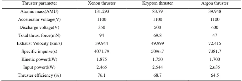
Table 1. Comparison results of three propellant thrusters
Thruster parameter Xenon thruster Krypton thruster Argon thruster
Atomic mass(AMU) 131.293 83.79 39.948
Accelerator voltage(V) 1100 1100 1100
Discharge voltage(V) 350 500 600
Total thrust force(mN) 94 69.8 47
Exhaust Velocity (km/s) 39.944 49.999 72.415
Specific impulse(s) 4071.79 5096.7 7381.7
Kinetic power(kW) 1.875 1.750 1.700
Input power(kW) 2.465 2.544 2.635
Thruster efficiency (%) 76.1 68.7 64.5
3.Conclusions
The total thrust force, specific impulse, input power and thruster efficiency are 94mN, 4071.79s, 2.465kW and 76.1% respectively in xenon propellant thruster. Thus, xenon propellant of thruster parameter result is reached within the thruster parameter limitation.The most propellant used in ionic thruster is xenon, which is easily ionized and has high atomic mass, thus generating a desirable level of thrust. Although the input power and exhaust velocity is smaller than krypton and argon, xenon propellant is higher thrust and thruster efficiency more than the two propellants. Therefore, xenon propellant is affordable for ionic thruster. For comparing the ion thruster thrust force results of the different types of propellant, the ion current density is the main parameter for thrust formation calculation. In calculation of plasma's electron current density at thermionic cathode and double sheaths the result is so large to compare the suitable result because it is difficult to determine those parameters in plasma.
Acknowledgements
The author expresses appreciation for the criticism of the referees, as a way of improving this paper. This project was supported by MAEU.
References
[1] M. Lieberman and A. Lichtenberg, “Principles of Plasma Discharges and Materials Processing”, New York: John Wiley and Sons, 1994.
[2] F. F. Chen, “Introduction to Plasma Physics and Controlled Fusion”, vol. 1, New York: Plenum Press, 1984.
[3] D. M. Goebel and I. Katz, “Fundamentals of Electric Propulsion: Ion and Hall Thrusters”, 1st ed. Hoboken, New Jersey: John Wiley & Sons, 2008.
[4] I. G. Mikellides, I. Katz, and M. Mandell, “A 1-D Model of the Hall-Effect Thruster with an Exhaust Region,” 37th Joint Propulsion Conference, Salt Lake City, Nevada, July 8–11, 2001.
[5] G. R. Brewer, “Ion Propulsion Technology and Applications”, New York: Gordon and Breach, 1970.
[6] D. G. Fearn, Angela S. Cox, D. R. Moffitt, "An investigation of the initiation of hollow cathode discharge" Royal Aircraft Establishment Technical Report.
[7] R. H. Goddard, “The Green Notebooks”, vol. 1, The Dr. Robert H. Goddard Collection at the Clark University Archives, Clark University, Worchester, Massachusetts.