Copyright © 2014 IJECCE, All right reserved
Simulation and Determination of the Laws Control of
the SRM for the Integrated Starter Generator
Application
M. Boudouda
GMP-CReSTIC Laboratory University of Champagne-Ardenne 9, Rue du Québec 10023 Troyes Cedex- Frence,
Email: [email protected]
F. Naceri
Department of Electrical Engineering, Batna University
Email: [email protected]
Abstract–This paper deals with the design of an integrated starter generator system for a car flywheel based on the Switched Reluctance Machine (SRM) technology. First, we discuss about the starter generator problematic following the results of our bibliography research. Secondly, we briefly remained generalities about the SRM and the determination of the laws control. In addition, we designed the converter associated to the machine using (Matlab/Simulink) software in order to identify the laws control and to adapt the operating modes (motor, generator, booster, brake). Finally, simulations of the open and closed loop model were performed on the converter with the (SRM).
Keywords–Switched Reluctance Machine (SRM), Starter-Generator, Law Control, Matlab-Simulink, Dspace System.
I. I
NTRODUCTIONDemands of the European automotive sector to reduce fuel consumption and pollutant emissions need an optimised exploitation of electrical energy [1].
In this type of system, an electrical device should function as both a motor and generator [2], operates at high power variations under very wide speed range. In addition, this application must be embedded in a car. This, implies that the physical envelope is highly constrained (limited to the space available under a hood) and the temperature could vary from -30°C to +130°C
Moreover, the end users require that these solutions should be reliable, robust and inexpensive. For this application, the switched reluctance machine is a better solution, because of its robust structure, than other types of machines [3], such as asynchronous machines or the wound rotor of synchronous machines [4].
That is why the work presented here suggests to evaluate the potential of this technology. Initially, the paper presents the problem of the starter/generator based of the switched reluctance machine (SRM).
Then, we detailed the constitution, the principle and the SRM structure.[5] Finally, simulations were carried out in order to validate technical specifications for all operating modes (starter, generator, booster , braking) and to determine the laws control on open loop, then closed loop [6].
II. S
TARTERG
ENERATORP
ROBLEMATICDuring the last years, the automotive manufacturers have been interested in combining the starter and the generator into one unit [7].
The concept of this integrated starter/generator system is to use an SRM, that incorporates the flywheel mounted on the crankshaft, between the engine and the gear box [8].
A. Choice of the Starter Generator based on the
switched reluctance machine
The SRM was chosen for its structural simplicity, low cost, robustness, capability to develop high torque at low speed and good efficiency. It is successfully used in many applications such as: electric traction motors, starter-generators for aircraft engine [9], high speed applications.
However, it has some disadvantages: auto-control necessity, high current ripple and a consequently noise[10].
B. Integrated Starter Generator Functions
This system must ensure the following operating modes: •
Starting:
From 0 to 100rpm, the system should ensure the starting of the engine during a time that not exceed few milliseconds, then the SRM must provide a high torque about 160Nm in order to activate the thermal engine pistons•
Generator:
From 800rpm, the SRM should function as a traditional alternator in order to recharge the engine battery and provide the power for the accessories (headlights, various actuators...). It must deliver a constant power of 3KW between 800-6000rpm•
Booster:
Stop and Go function for urban traffic, i.e. the restarting of the thermal motor in order to decrease the pollutants emissions.III. S
WITCHEDR
ELUCTANCEM
ACHINEA. Constitution of the SRM
This type of switched reluctance machine [11], has a toothed rotor with Nbtr: number teeth of the rotor, and a toothed winding stator with Nbts: number teeth of the stator. This machine does not contain the excitation circuit (see fig.1). The two pole parts are carried out by sheet stacking of ferromagnetic material.
B. Flux- Position- Amps- Turns diagram
In the Switched reluctance machine, the flux varies versus the rotor position and the amps turns injected into a phase:Φ= function (Ns.i,θ)
As shown in fig.2, we represent the characteristic of the machine and this form of the inductance (or of permeance) [12].
Fig.1. Constitution of the SRM
Fig.2. flux- position- amps-tour Diagramm Notions of energy and coenergy are defined by
Energy: Wem
i. Eq. 1-1Coenergy: Wcem
. i Eq. 1-2 Which represents the hatched surfaces on the Figure 2.IV. G
EOMETRY OF THES
TARTERG
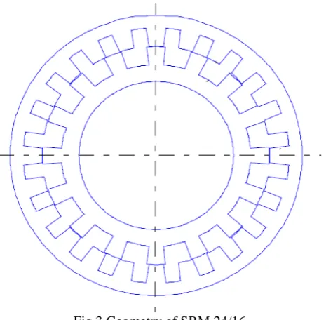
ENERATORFig 3 Geometry of SRM 24/16
Electromagnetic characteristics:
• q = 3 Number of phases
• Ns = 10 Number of wires per phase • Nbdr = 16 Rotor tooth number • Nbds = 24 Stator tooth number • Pn = 3 kW Nominal power
Fig.4. flux- position- amps- turns SRM 24 /16 Diagram Figure 4 illustrates the saturation phenomenon which occurs when current values exceed 100amps.
V. S
IMULATIONSCopyright © 2014 IJECCE, All right reserved We also developed the control parameters for the look up
tables for the closed loop system. A. Simulation principle
The purpose is to simulate the function of the switched reluctance machine in motor and generator operating mode from static data Flux = function (position, current) calculated by finite elements.
We numerically solve the principal equation for different control angles, for input speed under a battery voltage, taking account the number of other sensitive parameters of the Electrical system . [14]
The principle schematic is as follow:
Electrical Equation
The following equations describe the voltage (V) applied into the machine phase [15] :
Eq. 1-3 In the linear case:φ= L(θ)i and the last equation can be written as :
Eq. 1-4 The inductance variation term versus the position i.ω.(dL/dθ) is called counter electromotive force (e.m.f).
Fig.5. Block diagram of the open loop control
B. Presentation of the simulation model
In this part, we explain the principle of our simulation model and the function of different blocks. Figure 5 presents the complete model used for different simulations and connection between the main diagrams blocks.
The (srm3ph) block, presents the SRM model functioning on motor and generator. This one, was designed by (Flux 2D, Flux 3D) software, and calculated by finite element. In the output of this block, we recover the 3 added currents, flux and the torque. Then, the
currents are reinjected in the current limitation block (dmic3ph), compared to the order value which is the maximum one. Each speed corresponds to a position injected in the input of the machine model. All the data processed by (com3ph) block has the following inputs: Rotor Angle : Motor position
θON,θFW,θOFF: From these control angles and for each
M/G : To select between functioning modes (1 : Motor– 0 : Generator).
Bottom_Cmd In: The input value of the current limitation (Chopping Current ).
In the output of this block, we recover the laws control which are reinjected to the inverter power bridge (block adts3ph) and the (batt+Filtre1) block, represents our battery state model and the parameters.
Efficiency and average values (capacitor, battery power, battery current) are displayed during the simulation. Otherwise, the efficiency, average currents values and losses of (MOS & Diode) for the inverter are calculated with (Power Device
Calculator) block. However, in this case we don’tdesign the load of the engine equipment, we oriented our model for the possibility to use our machine us a starter and generator.
VI. S
IMULATIONSR
ESULTSSimulations were carried out from Matlab programs and the design developed with Matlab/Simulink [16]
A. Open loop simulations
The problematic of the open loop simulations of proposed machine is in the following terms :
- To findθON,θFW,θOFF, control angles used to define the
control parameters of our machine.
- Simulations of our battery model with different values of capacity and resistance.
θON: Conduction angle θFW: Freewheel angle θOFF: OFF angle
B. Wave forms
The simulation results in open loop model of the system allow to study different operating modes. We did many simulations with different control parameters in order to determinate the operating envelope.
The table represents the data for simulation points in each operating mode:
Motor modes : Starter & Booster
Motor Mode Starter Booster
Torque (N.m ) 100 28,73
Speed (rpm) 300 2000
Motor Power (W) 3142 6017
Battery Power (W) 12780 9327
Battery losses (W) 5450 2022
Min battery (Volt ) 21,8 28
DC Instantaneous Power (W)
7804 6104
Transistor losses (W) 419 156
Diodes losses (W) 31 22
Bridge losses (W) 2701 1068
Cap losses (W) 209 77
Total losses (-batt) 2991 1175
Motor losses (W) 6648 2135
Filter losses (W) 290 107
Starter Mode :
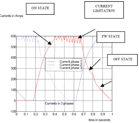
From 0 to 850 rpm, the system must ensure starting during a time that not exceed one hundred milliseconds and the SRM must provide a high torque (100Nm) [17].
Figure 6 shows the wave form of the 3 current phases in the case of a cold start operation (Rbat=35mΩ) with current limitation (600amps) and frequency (8Khz). In order to generate these currents in theSRM, it’s necessary to supply these phases during the inductance decrease [18] by modifying the control parameters (θON,θFW,θOFF).
In starting mode, we are interesting to obtain average torque greater than 100Nm. Figure 7 shows the waveforms of the battery voltage, corresponding to the power or required torque and the minimum voltage, which should not drop below 21V (min Ubat≥21V). So, if we decrease the battery voltage Ubat (less than 21V ), we reduce the torque ripple.
Fig.7. Wave forms of the Starter battery voltage
Alternator Mode Generator Braking
Torque (N.m ) -21,03 -26,56
Speed (rpm) 3000 2500
Motor Power (W) -6607 -6953
Batterie Power (W) -5087 -5244
Batt losses (W) 283 303
Min battery (Volt ) 42,5 42,0
DC Instantaneous Power (W)
Copyright © 2014 IJECCE, All right reserved
Transistor losses (W) 7 9
Diodes losses (W) 52 55
Bridge losses (W) 351 387
Cap losses (W) 22 46
Total losses (-batt) -377 -438
Motor losses (W) -1143 -1271
Filter losses (W) 26 51
Generator Mode:
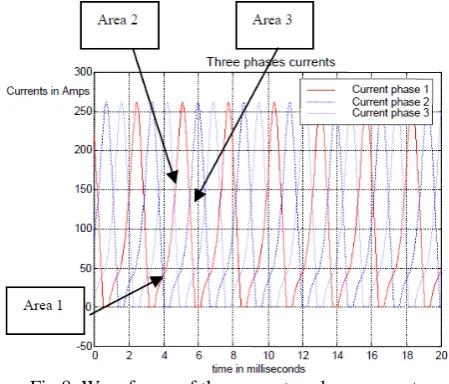
In this mode, the motor turn between 700 and 6000 rpm and should provide a 40.5V voltage on the continue network with a good efficiency and battery power of 6KW. Regarding the currents, we can distinguish 3 ranges; an up current area (see Area 1), an increase current area due to the counter electromotive force of the inductor variation (see Area 2), and decreasing current until its extinction in the process of free wheeling (see Area 3). The waveforms of the currents are shown bellow
Fig.8. Waveforms of the generator phase current The voltage waveform shows the various voltage resistive drops. Also, regarding the simulation on generator mode, our purpose is to find the control parameters that allow to maintain the battery voltage, low ripple of the battery voltage (Ubat) and the power battery delivered. (see Fig. 8).
Fig.9. Waveforms of the Generator battery voltage
C. Closed loop simulations
Initially, the open-loop simulations identified a range of control parameters on the basis of some predetermined angles, by manual calculation for different modes. It is from this angle that we created our look up tables and located them in our closed-loop system [19].
The diagram of the closed-loop simulation is the same as open-loop diagram, except the adjustment of laws control which is done by using the block (Generator Control Law).
In this case, speed is re-injected at the input block, and the torque order too, which takes the following values: - 0 to 100% : Motor mode
- 0 to–100% : Generator mode
Each torque and speed value, permit to determinate angles θON, θFW, θOFF and the current limitation value
(Chopping).
The table below represents the simulation results in closed loop.
Explanation of the table content:
The speeds (80rpm, 160rpm, 320rpm, 640rpm) correspond to the cold starting mode, which the required torque value is the maximum (Tmax≥100Nm). Then, we simulated with the torque values (80%Tmax, 40%Tmax, 20%Tmax, 10%Tmax).
We did the same for the speeds (1280rpm, 2560rpm, 5120rpm), that correspond to the booster mode operation at constant power 6KW and the torque value is calculated by the following equation:
P =T *ωT =P/ω
Example: for the speed 1280 rpmω= (1280 2*pi)/ 60 = 134.04 rd/sec
Torque = 6000/ 134.04 = 44.76Nm
This means that for each speed, the look up table dimension is (7X5), each speed value versus the torque, gives the θON, θFW, θOFF, Chopping parameters, which
allow to generate the control laws and to implement them in the block "Generator Control Law". Furthermore, if we want to simulate a value of speed that is not in the table, the block model provides an interpolation until desired values are found.
Speed
(rpm)
80 160 320 640 1280 2560 5120
Tmax
(Nm) 106.
9
105.8 99.05 72.55 44.76 22.38 11.28
ON (%) 56 54 52 40 37 21 23
OFF (%) 90 88 8 77 87 72 71
FW (%) 100 98 99 87 92 80 83
Chop
(Amps
600 600 600 600 600 600 600
D. Look up tables model
Fig.10. Look up tables schematic
VII. C
ONCLUSIONThe work carried out on this paper consisted of developing a calculated model on the Matlab/Simulink, in order to explore the possibilities of the switched reluctance machine on the starter/generator modes for automobiles applications and to simulate the operating machine in open loop and closed loop.
This model, also used to study the influence of inductor waveforms on the laws control and the study, has confirmed the relation between the currents and the inductor characteristics. At the same time, this model allowed us to make many simulations, which enable the confirmation of the compromise between our achieve design (maximum torque, power battery …etc) and our constraints (threshold voltage battery… etc.),especially, to determined the laws control of the look up tables.
Finally, all theses simulations enabled to validate our design model, and to verify experimentally the implementation of the look up tables of the laws control in the real time on the D space system (Hardware in the Loop), in order to check the tests and simulations results. The comparison between the experimental results and the simulations of the laws control will be presented in a future paper.
R
EFERENCES[1] Jawad faiz and K. Moayed zadeh, " Mode design of switched reluctance machine for starter/ generator of hybrid electric vehicle", Electric Power systems research, volume 75, Issues 2– 3, August 2005, pp. 153–460.
[2] A.V. Radun, C.A. Ferreira, E.Richter, “Twochannel switched reluctance starter/generator results” IEEE Transactions on Industry Applications, Issue Date: Sep/Oct 1998, Volume: 34 Issue 5, pp.1026–1034.
[3] A.Emadi, M.Ehsani, J.M. Miller “Vehicular Electric Power Systems”-land, sea, air and spaceapplications” Marcel Dekker Inc, New York, 2004, pp. 496.
[4] Liuchen Chang , " Switched reluctance motors: small motors of the next generation for automobiles ", Vehicular Technology Conference, 2003. VTC 2003-Fall. 2003 IEEE 58th on issue date: 6-9 Oct. 2003, Volume: 5, pp 3316–3320.
[5] Journal of Electric Engineering, http://www.jee.ro
[6] J.-P. Lecointe and R. Romary, " Five methods of statoral frequency determination: case of induction ans switched reluctance machines", Mechanical systems and signal processing, Volume 18, Issue 5, September 2004, pp. 1133– 159.
[7] M. Gabsi, A. De vires, and Al, «A Switched Reluctance Machine for a car starter alternator system", Proceedings IEMDC 2001. [8] Giuseppe S. Buja and Maria I. Valla «Variable structure control
of SRM Drive »,IECON’92, 9-13 November 1992,Vol. 1, pp. 482,487.
[9] M. Ali Akcayol and Cetin Elmas, NEFCLASS-based neuro fuzzy controller for SRM drive ,Engineering Applications of Artificial Intelligence, Volume 18, Issue 5, August 2005, Pages 595-602.
[10] A. Matveev, V. Kuzmichev, and E. Lomonova " A new comprehensive approach to estimation of end-effects in Switched Reluctance Motors ", Proceeding ICEM 2002, Bruges, Belgium, August 2002.
[11] Guy Grellet et Guy Clerc, "Actionneurs électriques ", Eyrolles 1999
[12] M. Gabsi, " Création d’effortsélectromagnétiques Machines à reluctance variable, Machines à aimants permanent", Polycopié de cours Maîtrise EEA-GE
[13] R. Inderka, M. Menne, and R. W. DeDonker, "Generator Operation of a Switched Reluctance Machine Drive for Electrical Vehicles", EPE'99.
[14] Hao Chen, J.J, Gu, "Implementation of the Three-Phase Switched Reluctance Machine System for Motors and Generators", Mechatronics, IEEE/ASME Transactions on, Issue Date: June 2010, Volume: 15 Issue:3, pp 421–432
[15] Sami Hassine, " Optimisation des paramètres de commande en tension des machines à réluctance variable autopilotées en régime permanent ", Thèse de l’université Paris 11 1992 [16] Stephen R. MacMin and William D. Jones, "A Very High Speed
Switched Reluctance Starter / Generator for Aircraft Engine Applications", IEEE IAS Conf. , 1989, pp1158-1764.
[17] I.Husain, " Minimization of torque ripple in SRM drives", IEEE Transactions on Industry Electronics , Vol 49, No 1 February 2002, pp 28-39
[18] M.Ehsani, I.Husain, and A.B. Kulkarni,“Elimination of discrete position sensor and current sensor in switched reluctance motor drives,” IEEE Trans. Ind. Appl.,vol 28, PP. 128-135, Jan./Fev 1992.