On the Design and Test of a Prototype of Biped
Actuated by Shape Memory Alloys
Amin Tohidi
a, Majid M. Moghaddam
aand Alireza Hadi
ba- Amin Tohidi: Mechanical Engineering Dept., Tarbiat Modares University, Tehran, 14115-111, IRAN Tel: +98 21 8283358; E-mail: amintohidi@ modares.ac.ir, and m.moghadam@ modares.ac.ir
b- Alireza Hadi, Ph.D. Graduate, University of Tehran, E-mail: [email protected]
A R T I C L E I N F O A B S T R A C T
Keywords:
Biped robot, SMA Actuator 5DOFs
In this paper the design of a biped robot actuated with Shape Memory Alloy (SMA) springs with minimum degrees of freedom is presented. SMA springs are a class of smart materials that are known for their high power to mass and volume ratios. It was shown that utilizing spring type of SMAs have many advantages as large deformation, smooth motion, silent and clean movement compared to ordinary type of actuators. In this work a Biped robot actuated through SMA springs with four DOFs is modeled and designed. Walking trajectory is generated validating the Zero Moment Point (ZMP) Criteria and the number of DOFs is modified accordingly. To verify the design, acomplete model of the biped actuated with SMA is modeled through computer simulation in MATLAB and Visual Nastaran. Finally to validate the results, a prototype is manufactured and tested. Experimental results showed reasonable agreement with simulation results.
1. Introduction
Most of biped walking robots consists of actuators (heavy servomotors), transmission systems (gearbox) and many DOFs to locomotate ([1, 2, 3]), resulting in relatively heavy (and large) walking robots.
Recently, miniaturization and simplification of robots has received increasing attention for multi-purpose use. In particular, the simplification of biped walking robots is an interesting and challenging problem. The first step of simplification is to delete extra parts or unnecessary DOFs. As we know, none of the existing biped walking robots is under 7 DOFs. In this paper, we present a walking robot that locomote through only5 DOFs. Further, to reduce the size and weight of the robot, we decided to use the SMA based spring materials to actuate the legs of the biped.SMA composites are class of smart materials that are known for their high power to mass and volume ratios. These actuators have many advantages as large deformation, smooth motion, silent and clean movement. These types of actuator don’t need any lubrication or protection from dust.
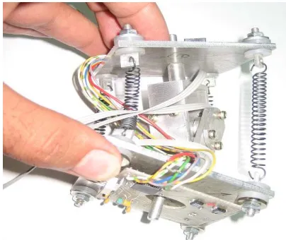
Fig. 1: Module parts
2. The Robot Design
The design of the robot consists of two parts: mechanical design and electrical design. The mechanical design is divided to two parts by itself: the module and the body design.
Fig. 2: The manufactured module 2.1. The Module Design
There are some studies on SMA module (joint), [5, 9]. Liu and Liao introduce a module with one DOF, [5]. This module is very simple but the deflection is limited and it has just one DOF, but locomotion needs at least two DOFs. Ying and Wang presented a two DOFs module that revolved in to plane [9], this module has high lost of energy because of friction in contact of SMA winding on disk. To provide two DOFs, large deflection and reduce friction, Hadi developed the Felexibot which is shown in Fig.1, [10]. Fig.2 shows the manufactured module.
This module consist of 7 parts, two flat plate, two U parts that make universal motion, two angular sensor to detect position, SMA connections and reserved space for electrical boards. This module has space work between + 30 deg to -30 deg in each revolution plan. Double couple of Hadi’s module was used in this biped as hip joints. Each joint has 2 DOFs and 6 SMAs.
2.1.The Body Design
At first a mechanism of locomotion with just four DOFs was proposed, but it was found that a mechanism with less than five DOFs is not appropriate to locomate the system . Adding a sliding part on top of the 4DOFs robot, the drawbacks of the motion was solved. The robot consists of six parts, two modules, two legs connected to the modules, a slider and few SMAs. The slider weight is used to transfer the center of the gravity of the biped. A rigid block sliding on a bar is used for this case, however, in practice it can be replaced with camera, battery pack, and other devices. Fig. 3 shows the biped including the actuator modules and the sliding weight COG compensator.
Fig. 3: Robot design 2.3 The Electrical Design
The block diagram of the module’s electrical hardware is shown in Fig. 4. It includes a microcontroller (ATMEGA32), SMA drivers (Darlington transistors, TIP122), position sensors, and communication drives. The microcontroller is used to manage the driving of the SMAs, to handle the communication requirements, and to provide A/D conversion.
SMA Spring Electronic
Board
Angular Sensor
Fig. 4: Electrical board overview
3. Modeling
To model robot motion, we should develop kinematic model of robot body and model of SMAs actuator behavior.
Fig. 5: Robot links and joint defenition 3.1. Kinematic Model
According to Fig. 5, robot is divided into 4 links and 5 joints. Refer to low reaction of SMAs actuators and ZMP criteria, acceleration terms is ignored, so ZMP criteria reduced to eq.1, describe kinematic model of robot and its stability region.
4 1 4 1 0 0 i i i i CGi CGm
R
m
R
(1)Where, 0
RCG is position matrix, in base coordinate
system.
3.2. SMAs Behavior Model
According to [11]:
Deflection of shape memory alloys as function of force and the martensite fraction can be expressed as:
s Gd D N F Gd N D
y
3 2 4 3 8 (2)
Which y is deflection, F is force, G is the elastic shear modulus, the phase transformation tensor (which can be calculated from ELwhere E is the elastic
modulus andLthe maximum recoverable strain), s is the stress induced martensite, D is outer diameter of shape memory alloys spring coil, d is wire diameter and N is number of winding.
In addition to the SMA spring model, the heat transfer model of the SMA is defined as:
) ( 2
I R hcAcT T dt
dT p
mc (3)
Ac=pi*d*L (4)
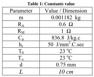
Which m is the mass, cpthe specific heat constant of
SMA, I current, R resistance of SMA, hc convection heat transfer constant, Acouter environment of SMA, d
SMA spring wires diameter and T ambient
temperature. Constant values are shown in Table 1.
Table 1: Constants value
Value / Dimension Parameter
0.001182 kg
m
0.6 Ω RA
1 Ω RM
836.8 J/kg.c
Cp
50 J/mm2.C.sec
hc
23 oC T0
23 oC T∞ 0.75 mm d 10 cm
L
The final model of the system in Simulink Matlab is shown in Fig. 6.
Communication Bus to other
modules Current CPU Memor y A/D Converter Communicatio n I/O
SMA Driver
SMA
Micro‐Controller
RS‐485
Communicatio n Module
Position
1 Force T
dT/dt eq deq/dt
s
Phase Transformation V
T
T
dT/dt Heat Transfer
du/dt Derivative Y
s
F
Constitutive Model -K-Constant 2
Deflection 1 Voltage
Fig. 6: SMA modeling in MATLAB software 4. Simulation
MATLAB and Visual Nastran software are used to simulate the locomotion of the robot. Actuators was are modeled in MATLAB environment and their actions are transformed to the Visual Nastran software to generate the biped body motion.
Both software are linked together in a range of 0.01s period. In doing so, inputs and outputs are defined in each software accordingly and the data in transferred through these for the communication purposes The input to the Matlab is the SMA’s positions are input and the resulting forces of the SMA’s based on their models are outputs to the V.N. software. Simulations are performed for a typical biped model and the results are shown in fig .7.
As it shows, the locomotion consists of tenth parts: first, move the slider to left, second, take off the right leg of the ground, third, swing forward the suspended leg, fourth, put the right leg to the ground, fifth, move the slider to the right, sixth, take forward robot with get back right let to first position and robot repeats above steps but support on right leg, thus continues trajectory makes walking forward.
5. Trajectory Generation
Through simulation, walking trajectories are generated. Then, through kinematic modeling of the biped, desired motions of the robot’s legs are calculated. It requires the motion of the modules that is actuated through SMA’s. The SMA’s are activated through two individual drivers. Fig .8 shows the simulation result.
Fig.8: Simulation results
6. Experiments
A scaled version of the biped is designed and manufactured to verify the simulation results in practice. Fig.9 shows the experimental setup. Specification parameter of assembly robot is collected to Table 2.
Fig. 9: Experimental setup Table 2: Robot specification
quantity parameter
1483 gr mass
30 cm Total Height
22 cm Leg Length
10 cm Width
SMA Actuator
14 Number Of Actuators
5 DOF
70*80 cm2 Foot Dimension
6 Amp- DC Supply
Aluminum Material
ATMEGA32 Microcontroller
33 mm per min. Locomotion Speed
Fig.10 shows SMAs spring arrangement in module and robot. To take off robot weight, should use double SMAs spring in corner of each module.
Fig. 10: SMA springs arrangement
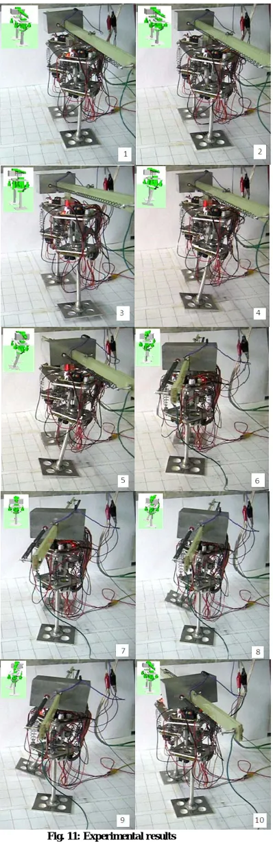
Fig. 11: Experimental results
generated automatically, and are repeated for a number of walking steps. Fig. 11 shows locomotion steps. It was found that the robot behaves stably, but due to the slow reactions of the SMA’s the overall speed of the robot was very slow. However, the SMA’s were shown to be properly strong to push the biped forward. Even though, the walking pattern was not very smooth in practice, but it proved that the motion can be generated through only 5 DOFs mechanisms.
7. Discussions
This paper presents the design of a biped robot actuated with Shape Memory Alloy (SMA) springs with minimum degrees of freedom. Modeling of SMAs and modeling of robot was shown, and the curved result used for experimental motion. So to simplify biped, extra DOF was deleted, therefore the biped moved with just 5 DOFs and actuated by SMAs. Finally a prototype of biped manufactured and locomate like simulation result.Experimental shows that SMA actuators in biped robot is useful, but apply this robot in corrosion surround, where other actuator will corroded, is suggested. Other advantage of this robot actuated by SMAs is maintenance free. This actuators work under water and in high duty conditions well.
References
[1] M. Vukobratovic and D. Juricic, “Contribution to the Synthesis of Biped Gait”, IEEE Trans. on Bio-Medical Engineering, 16, no.1,1969,1-6.
[2] K. Hirai, “Current and Future Perspecive of Honda Humanoid Robot”, IEEE/RSJ International Conference on Intelligent Robots and Systems, 2, 1997, 500-508.
[3]Y. Kuroki, “A small biped entertainment robot”,
International Symposium on Micromechatronics and Human Science, 2001, 3-4.
[4]Hyung-Min Son, Jun-Bum Gul, Se-Hoon Park, Yun-Jung Lee, Tae-Hyun, “ Design of new quadruped robot with SMA actuators for dynamic walking”, SICE-ICASE
International Joint Conference, Bexco, Busan,
Korea,2006.
[5]C. Y. Liu, W. H. Liao,” A Snake Robot Using Shape Memory Alloys”, International Conference of IEEE on Robotics and Biomimetics, Shenyang, China, August 2004, 601 – 605.
[6]Mami Nishida, Kazuo Tanaka, Hua O. Wang,” Development and Control of a Micro Biped Walking Robot using Shape Memory Alloys”, International Conference of IEEE on Robotics and Automation,Orlando, Florida , May 2006, 1604 – 1609.
[7]Ehsan Tarkesh Esfahani, Mohammad H. Elahinia,” Stable Walking Pattern for an SMA-Actuated Biped”
,IEEE/ASME Transaction on Mechatronics,
12(5),October 2007.
[8]Junichi Urata, Tomoaki Yoshikai, Ikuo Mizuuchi and Masayuki Inaba,” Design of High D.O.F. Mobile Micro Robot Using Electrical Resistance Control of Shape Memory Alloy”, International Conference of IEEE/RSJ on Intelligent Robots and Systems,San Diego, CA, USA,
Oct 29 - Nov 2, 2007, 3828 – 3833.
[9]Shenshun Ying, Xianshen Qin and Qiong Liu,” Design and Research of Robot Joint Actuated by SMA Wire”,
Proceedings of the IEEE International Conference on
Robotics and Biomimetics ,sanya,china, December
2007.
[10] A. Hadi, A. Yousefi-Koma, M. M. Moghadam, M.Elahinia ,A. Ghazavi, “Developing a Novel SMA-Actuated Robotic Module,” Sensors and Actuators A: Physical, 162:72-81, 2010.
[11] L. C. Brinson, “One-dimensional constitutive behavior of shape memory alloys: Thermo-mechanical derivation with non-constant material functions and redefined martensite internal variable,” Journal of intelligent material systems and structures, 4, April 1993, 229–242. Biography of Authors
Majid M. Moghaddam received his
B.Sc. degree in Mechanical Engineering in 1988 from Sharif University of Technology, Iran, and M. Eng. degree in Mechanical Engineering in 1993 from McGill University, Canada, and Ph.D. degree in Mechanical Engineering in 1996 from University of Toronto, Canada. He is a professor of mechanical engineering at Tarbiat Modares University, Tehran, Iran. His current research, which focuses on applied robotics and robust H∞ control, is concerned with haptic
robotics, rehabilitation robotics, inspection robotic sand rough terrain mobile robot design. He is a member of the Administrative Committee of Mechatronics Society of Iran. He has served as co-chair for many national/international conferences in Iran.
Alireza Hadi received a B.S. degree