0 INTRODUCTION
Nuclear power plants are designed for more than 40
years of service life [1], but due to the aggressive
operational conditions, unforeseen environmental conditions and material behaviour at elevated temperatures, the overall service life of the plant is
affected [2]. One such problem was encountered in
the residual heat removal system of the Civaux-1
power plant, France [3]. Due to higher toughness
and superior corrosion resistance, austenitic stainless steels are used in the piping system of nuclear reactors
[4]. AISI 321 is used in the secondary circuits of the water-water energetic reactor (WWER) nuclear power plants and heat exchangers. SS304 and SS304L are
frequently used in pressurized water reactors [5].
SS316, SS316L, and SS316LN are mostly used in
the piping system of light water reactors (LWR), and
liquid metal cooled fast breeder reactors (LMFBR)
[6]. Although tough, these components undergo
complex thermo-mechanical cycles during plant operations [7]. Varying temperatures in piping systems due to thermal stratifications, turbulent mixing of the hot and cold fluid and vortex penetration in different regions of the system, such as mixing tees,
joints, and valves [8], result in thermal fatigue of
such components [9]. Austenitic stainless steel can
be primarily affected by these thermal fluctuations because of their high thermal expansion coefficient
and low fatigue endurance limit [10]. The mechanism
of fatigue crack initiation and propagation is similar in the case of thermal and mechanical loading conditions
[11] and [12]. Though thermal fatigue damage has
been proven to be more damaging than uniaxial isothermal fatigue [13] and [14], both are administered by the same fatigue mechanism. Out of these multiple cracks, only dominant cracks grow faster [15]. Cracks may nucleate from the well-developed slip bands, defects, inclusions, non-metallic impurities, or surface imperfections [16]. These geometrical discontinuities
Studying the Effect of Thermal Fatigue on Multiple Cracks
Propagating in an SS316L Thin Flange on a Shaft Specimen
Using a Multi-Physics Numerical Simulation Model
Mukhtar, F. – Qayyum, F. – Hassan Elahi, H. – Shah, M.Fariha Mukhtar1 – Faisal Qayyum2 – Hassan Elahi3,* – Masood Shah1
1 University of Engineering and Technology, Department of Mechanical Engineering, Pakistan 2 Technische Universität Bergakademie Freiberg, Institute for Metal Forming, Germany 3 Sapienza University of Rome, Department of Mechanical and Aerospace Engineering, Italy
After more than a decade of research on thermal fatigue cracking in nuclear reactor components, the science remains incomplete. It is essential to understand the crack propagation behaviour and the influence of multiple cracks on the fatigue life of a component due to thermal fatigue load. Accurate numerical simulation modelling can help in better understanding the influence of different factors on failure propagation. In this research, a finite element-based numerical simulation model has been developed using ABAQUS commercial software to obtain insight into crack propagation and crack arrest in an SS316L thin flange on shaft specimen; the assembly is cooled internally, and cyclic thermal loading is applied on the flange rim. The experiment was carried out on a specially designed rig using an induction coil for heating the outer rim. Thermocouples were attached radially on the rim to collect detailed temperature profiles. Real-time temperature-dependent elastic-plastic material data was used for modelling. The boundary conditions and thermal profile used for the numerical model were matched with experimental data. The stresses responsible for crack initiation, the effect of crack number and crack lengths on stresses, energy absorbed at the crack tip after every thermal cycle and the threshold values of cracks are evaluated in the current work. The obtained simulation results were validated by comparing experimental observations. The developed simulation model helps in better understanding the evolution of stresses and strains in uncracked and cracked SS316L discs mounted on a flange due to thermal cycling. It also helped in better understanding the crack propagation behaviour and the evolution of energy release at crack tips. Such a model can help future researchers in designing components undergoing thermal fatigue loading, for example, in nuclear power plants.
Keywords: thermal fatigue, numerical simulation, SS316L, hoop stress, crack propagation, J-integral
Highlights
• Thermal loads occurring in nuclear power plants were used as boundary conditions. • A detailed temperature-dependent material model of SS316L was used during the simulation. • Crack initiation and propagation were observed to estimate the fatigue life of the SS316L disc. • Ratcheting behaviour of SS316L results in plastic deformation and blunting of the crack tip.
are present due to the adopted manufacturing process
[17] and act as crack initiation sites during service
[18] and [19]. The number of cycles to fatigue failure will significantly be decreased if the temperature
is increased abruptly [20]. A fatigue crack, when
initiated, grows slowly until the critical crack length is reached, after which the fatigue crack growth rate increases and leads to the failure of the component. Due to the lack of a thermal fatigue test standard, different experimental arrangements have been proposed by researchers for the thermal fatigue testing
of materials [12] and [21]. Generally, researchers
develop setups that are closer to actual conditions. For example, a two- and three-dimensional loading
condition Splash test facility and FAT3D [22]. Other
researchers for thermal fatigue testing of austenitic stainless-steel grades 304L, 316L were carried out under different temperature ranges for evaluating the crack initiation and propagation in pressurized water reactor (PWR) and LMFBR conditions using a SPLASH test facility [23].
Although several well-equipped experimental setups have been developed by researchers, it is still problematic and sometimes impossible to record critical material deformation and failure data while the test is in progress. Numerical simulation models developed in the past to study the fatigue life of metals
[24], ceramics [25] and [26] and polymers [27] and [28]
help understand the material deformation and failure behaviour under varying boundary and geometric conditions. They significantly contribute to reducing design cost and time.
Ullah et al. [29] showed that numerical simulation models could help in better understanding the fatigue crack propagation in material under complex thermo-mechanical loading conditions. Such models were also used to estimate the fatigue life of composite
materials under dynamic loading conditions [30] and
[31]. Recently, based on elastic-plastic material data and realistic boundary conditions, a method was
developed by Qayyum et al. [15] to numerically model
the crack propagation in complicated structures due to thermal fatigue. Such a model helps in successfully obtaining a deep insight into the complex thermal fatigue phenomena and therefore is adopted here.
In this research, a flange-shaft specimen made of SS316L is experimentally tested under thermal fatigue loading provided by induction heating and internal cooling. The simulation was developed by incorporating real-time temperature-dependent elastic-plastic material data to obtain insight into stress distribution and crack propagation in a flange rim.
1 EXPERIMENTATION
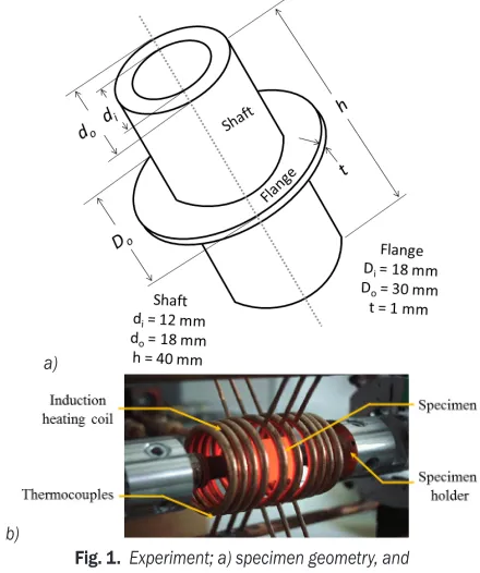
The specimen consisted of a hollow shaft of SS316L on which a flange was machined as an integral part. Specimen geometry and dimensions are shown in Fig. 1a. The idea behind using a thin flange is to have a plane stress condition at the crack tip for a more straightforward analysis. The experiment was carried out in collaboration with French partners at Ecole D’ Mines, Albi, France. The specimen was heated rapidly by 2 MHz high-frequency induction heating and cooled internally by flowing water at room temperature. One thermal cycle lasts for 16 seconds, with 4 seconds of heating and 12 seconds of subsequent cooling. The experimental arrangement is shown in Fig. 1b.
The intended temperature profile was maintained and recorded with the help of spot-welded thermocouples at 0 mm, 2.75 mm, and 4.4 mm from the outer rim of the flange. The temperature profile obtained from experimentation is shown in Fig. 2 with the help of solid lines.
a)
b)
Fig. 1. Experiment; a) specimen geometry, and b) induction heating of the specimen
2 NUMERICAL SIMULATION
thermo-mechanical approach is used with a non-linear rate-independent elastic-plastic material model, as suggested by Fissolo et al. [13].
Fig. 2. Thermal profile matching the description of thermocouple positioning
2.1 Material Data
SS316L is a non-hardenable and non-magnetic grade of stainless steel. It is used where toughness and
corrosion resistance are equally important [10]. The
temperature-dependent material properties of SS316L, which are listed in Table 1, were incorporated in the numerical simulation model. The flow curves of the material at different temperatures are presented in Fig. 3. This temperature-dependent elastic-plastic material data was used in the numerical model definition.
Table 1. The temperature of dependent mechanical properties of SS316L [32]
Temperature [°C]
Young’s modulus [GPa]
Thermal conductivity [W/(mm·K)]
Thermal expansion coefficient
[10–5/°C]
Specific heat [kJ/(kg·K)]
25 200 0.014 1.60 464.68
100 194 0.0149 1.66
-200 185 0.016 -
-300 177 0.0173 -
-400 169 0.0186 - 515.6
500 160 0.0199 -
-800 135 0.02 569.2
871 - - 1.98
-2.2 Loading and Constraints
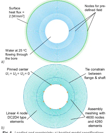
Thermal heat flux of 2 W/mm² was applied at the rim of the disc in all simulation models. The temperature profiles at different depths in the numerical simulation model were matched with experimentally observed profiles by tuning the amplitude of heat flux and
cooling. The simulation was run for 30 fatigue cycles to obtain a stabilized stress-strain response. The boundary conditions defined for all simulation models are shown in Fig. 4a. Pinned boundary condition was applied at the internal periphery of the shaft. Element type DC2D4 (4-node linear heat transfer quadrilateral) was used to generate a total of 4260 linear quadrilateral elements on the whole assembly. The meshed assembly of disc and shaft
Fig. 3. Temperature-dependent plasticity data of SS316L [32]
a)
b)
is shown in Fig. 4b. The model was checked for the mesh dependency and, during meshing, the aspect ratio (which is a measure of how well structured the mesh is, i.e., the perfect aspect ratio is 1.0) was maintained below 1.05. The readers are encouraged to refer to previous publications [33] and [34] to obtain more details about the numerical simulation model development, meshing, boundary conditions, and post-processing of data.
2.3 Mechanical Model
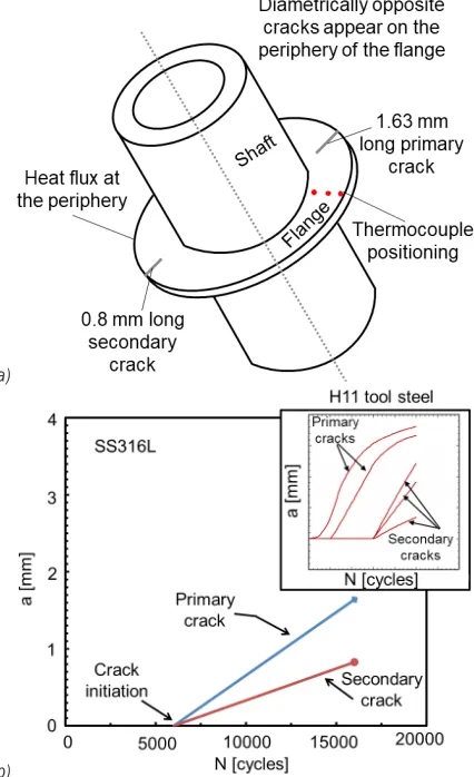
A total of 29 models were developed for this research with different crack lengths and numbers of cracks. The simulations were based on the sequence published earlier [12] and [35]. A thermal analysis was run, and the temperature evolution at each node was recorded to obtain nodal temperature distributions. A model was developed to study the effect of thermal cycling on the uncracked sample, which results in the highest hoop stresses. Twenty-seven models with different crack numbers and crack lengths were analysed to study the effect of varying crack numbers and crack lengths on evolving stresses at the periphery of the disc. The description of peripheral cracks is shown in Fig. 5.
Fig. 5. Description of peripheral cracks in the specimen
3 RESULTS
Experimentally, it is observed that two diametrically opposite cracks initiate at the outer periphery of the flange. Cracks initiate in the flange after 6,000 thermal cycles. The two cracks originated were 180° apart from each other, the fatigue crack growth behavior of these cracks is presented in Fig. 6b. The same phenomenon of cracking was observed previously in the case of the H-11 tool steel disc [15]. In the case
of H-11 tool steel, multiple cracks originated on the periphery, out of which only eight cracks propagated throughout the experiment, which was validated through numerical simulation, whereas in this case only two noticeable cracks initiated and propagated up to 16,000 cycles. One of the cracks propagated to a crack length of 1640 µm, and the other grew up to 825 µm for the same number of cycles. The number of cycles to crack initiation and the significant crack lengths attained by the two cracks are shown in Fig. 6b.
a)
b)
Fig. 6. Experimental results; a) no. of cycles to crack initiation, and b) diametrically opposite cracks as a result of thermal fatigue
3.1 Temperature- Stress Correspondence
first cycle (from 0 to 1) shows a sudden increase in stress with increased temperature. Compressive stresses develop in the disc (from 1 to 2) when the temperature is raised while they start to transform into tensile stresses (from 2 to 3) during the cooling period. Tensile stress reaches a maximum magnitude of 396 MPa in the last cycle at point 4, which shows a 21 % increase in stress as compared to the 1st cycle.
These stresses are responsible for the crack initiation in the disc. When the first and last cycle compressive stresses are compared, 13.4 % elevation is observed at point 2.
Fig. 7. Stress-temperature hysteresis of SS316L and H11 tool steel (for comparison)
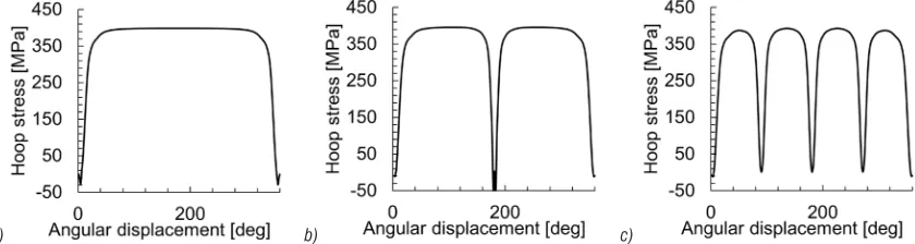
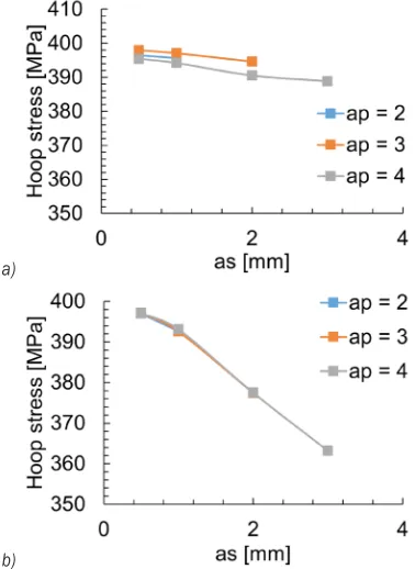
3.2 Effect of Crack Lengths and Number of Cracks on Hoop Stress
Maximum hoops stress is observed on the rim of the flange. The variation in hoop stress on the rim due to cracking forms plateaus of hoop stresses which are presented in Fig. 8. In this figure, n is the number of cracks, ap is the length of the primary crack, as is the length of the secondary crack. The graph shows that
hoop stress suddenly falls when a crack is introduced in the specimen. The initiation of the crack and its opening in the cooling cycle results in stress relief. An increasing number of cracks results in an overall decrease in hoop stress on the rim. By comparing Fig. 8a with Fig. 8b, it is observed that introducing a crack causes sudden stress relaxation at a particular point on the rim.
In the case of the SS316L disc, only two cracks initiate and propagate to significant lengths during the experimentation. This validates the numerical simulation results in which a 7 % drop in hoop stress is recorded when the crack number increases from 2 to 4, i.e., from Fig. 8b to Fig. 8c.
In Fig. 9, the secondary crack length is plotted as a function of hoop stress for different primary crack lengths. For every set of primary crack lengths, i.e., 2 mm, the hoop stress decreases with an increase in secondary crack length; the same is true for the set where primary crack length is kept at 3 mm and 4mm respectively. For a 2 mm secondary crack, hoop stress has a maximum value of 396 MPa. The minimum
value of hoop stress for n = 4 is recorded when the
primary crack length is 4 mm, and the secondary crack length is 3 mm.
3.3 Crack Propagation Phenomenon
Anderson [36] has explained that either J-integral or the crack tip opening displacement (CTOD) can be used as a fracture criterion for time-independent, elastic-plastic behaviour of materials that are to be dealt with in non-linear elastic-plastic fracture mechanics. Both J-integral and CTOD give information about the crack- tip condition. Researchers have also associated the fatigue crack growth to the cyclic J-integral [37]. The time response of J-integral resulted in spikes, as shown in Fig. 10. Spikes are formed as a result of sudden rises and falls in the values of J-integral, which is governed by continuous thermal cycling of
a) b) c)
the flange. During the tension cycle, the crack opens, which results in the release of energy while in the compression cycle the crack remains closed; hence, no energy is being released. This release in energy results in crack propagation during the cooling cycle. The J-integral trend, in this case, is comparatively different from that observed in the case of H-11 tool steel. Although the spikes formed in the case of H-11 tool steel were comparable to that of SS316L, the J-integral does not become stabilized with subsequent thermal cycling in SS316L; the values seem shifted from the horizontal axis.
a)
b)
Fig. 9. Maximum hoop stress as a function of secondary crack length; a) for n = 2, and b) for n = 4
Fig. 10. J-integral vs. time; for n = 1
The graph shown in Fig. 11 is the response of crack mouth opening displacement (CMOD) with respect to time. CMOD increases with time after every cycle. It is maximum at the instance at which tensile stress is maximum, i.e., at the end of every thermal cycle. The overall shift in the value of CMOD from the horizontal axis represents the cumulative plastic deformation at the crack tip, which is adding specific value to its displacement response taken for the last 12 cycles.
Fig. 11. CMOD vs. time for last 12 cycles, n = 1, ap = 1 mm
4 DISCUSSION
Maximum hoop stress is observed on the rim of the flange. The hoop stress is compressive during heating, reduces to zero, and eventually becomes tensile during cooling due to retained plasticity. In this research, these stresses were analysed using calibrated thermal and mechanical models, and it was observed that an energy hysteresis is observed in the case of SS316L with an increasing area. This shows that there is continuous energy absorption at the crack tip.
The crack initiation was not the main focus in this research but has been previously investigated to occur due to dislocations accumulation at grain boundaries, or inclusions or voids to form micro-cracks, which eventually join together to form a bigger crack, which grows larger under the influence of tensile stresses.
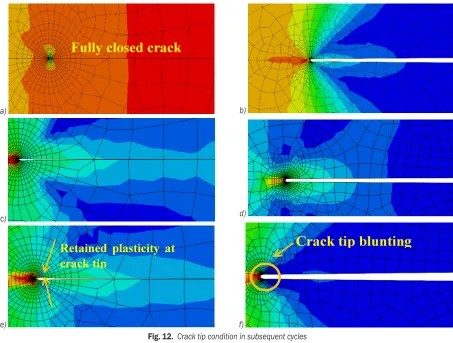
During each thermal cycle, a complex phenomenon occurs at the crack tip. This research was carried out to see and understand this phenomenon in a better way. In the first thermal cycle during heating, the material softens, and compressive hoop stresses accumulate on the rim of the flange, and the crack faces close, as shown in Fig. 12a. Tensile hoop stresses originate during cooling, which is responsible for crack opening, as can be observed in Fig. 12b.
behaviour. Energy absorption at crack tip results in crack tip blunting and with subsequent thermal cycles the crack tip does not close even at the highest temperature. This can be seen for the 5th cycle in Figs.
12c and d and for the 30th cycle in Figs. 12e, and f.
The J-integral shows an increasing trend with the increase in crack length in Fig. 10. The J-integral reaches its maximum value after 30 cycles. It is observed that the J-integral increases with an increase in crack length up to 2 mm. There is a 15.33 % increase in energy release rate when the crack grows from 1 mm to 2 mm. On further increasing the crack length up to 3 mm, the maximum value of the energy release rate was approximately the same as that for a crack length of 1 mm. On further increase in crack length from 2 mm to 3 mm and 4 mm, 15.34 % and 29 % drops in corresponding values of J-integral are recorded.
CMOD and CTOD are the two parameters that are also used to estimate the crack growth rate. Researchers have associated the fatigue crack
propagation to the CMOD [38]. CMOD increases
a)
c)
e)
b)
d)
f)
Fig. 12. Crack tip condition in subsequent cycles
a) 1st compression cycle, b) 1st tension cycle, c) 5th compression cycle, d) 5th tension cycle, e) 30th compression cycle, f) 30th tension cycle
with an increase in crack length, as shown in Fig. 11. 0.61 % decrease in hoop stress is observed where the number of cracks remains the same while secondary crack length increases from 1 mm to 2 mm. For both the cases, i.e. n = 2 and n = 4, CMOD increases with an increase in secondary crack length. An overall
decrease can be seen in Fig. 11, when n = 4 which
points towards the limitation of the number of cracks on the periphery. Fig. 11 shows that CMOD increases with an increase in primary crack length. The relationship curve between primary crack length and CMOD for n = 4 overlaps with n = 2. It shows that for greater crack length, CMOD will be more independent of the number of cracks.
5 CONCLUSIONS
of the disc type specimen of SS316L under cyclic thermal loading provided by the induction heating and internal cooling. The experiment resulted in two diametrically opposed cracks, which propagated to 1640 µm and 825 µm in length. The results of the numerical simulation give the agreeable validation of the experiment. The obtained results can be concluded as follows:
• Material permanently deforms in the first thermal cycle. During thermal cycling, stress reverses itself and results in a stress-strain hysteresis. The pair of stresses developed in the specimen exceeds the fatigue endurance limit of the material. • Hoop stress on the flange stands responsible for
crack initiation in it. When the number of cracks
is increased from n = 2 to n = 4, a maximum
drop of 6.4 % in hoop stress is recorded, which justifies the two-crack formation phenomenon during experimentation.
• The J-integral gave us the possible range of primary crack length, which is 0.5 mm ≤ ap ≤ 2.5 mm while there is enough energy available in the specimen to drive the secondary crack up to 2 mm.
• CMOD increases regardless of the number of cracks or crack length, thus cannot be relied on as a suitable identifier of thermal fatigue damage. • The time response of J-integral and CMOD points
towards the ratcheting behaviour of SS316L and crack blunting in the specimen.
7 NOMENCLATURE
n number of cracks
N number of cycles
a crack length, [mm]
as secondary crack length, [mm]
ap primary crack length, [mm]
U1 displacement in X-direction
U2 displacement in Y-direction
U3 displacement in Z-direction
di pipe inner diameter, [mm]
do pipe outer diameter, [mm]
h height of pipe, [mm]
Di flange inner diameter, [mm]
Do flange outer diameter,[mm]
t thickness of flange, [mm]
8 REFERENCES
[1] Le Duff, J.-A., Ould, P., Bernard, J.-L. (1996). Fatigue crack initiation and propagation in austenitic stainless steels for light water reactors. International Journal of Pressure Vessels
and Piping, vol. 65, no. 3, p. 241-253, DOI:10.1016/0308-0161(94)00135-6.
[2] Paffumi, E., Nilsson, K.-F., Szaraz, Z. (2015). Experimental and numerical assessment of thermal fatigue in 316 austenitic steel pipes. Engineering Failure Analysis, vol. 47, p. 312-327,
DOI:10.1016/j.engfailanal.2014.01.010.
[3] Cipière, M.F., Le Duff, J.A. (2002). Thermal fatigue experience in french piping: Influence of surface condition and weld local geometry. Welding in the World, vol. 46, no. 1-2, p. 23-27,
DOI:10.1007/BF03266362.
[4] Avner, S.H. (1974). Introduction to Physical Metallurgy. McGraw-Hill, New York.
[5] Kadlec, M., Haušild, P., Siegl, J., Materna, A., Bystrianský, J. (2012). Thermal fatigue crack growth in stainless steel.
International Journal of Pressure Vessels and Piping, vol. 98, p. 89-94, DOI:10.1016/j.ijpvp.2012.07.005.
[6] Prasad Reddy, G.V., Kannan, R., Mariappan, K., Sandhya, R., Sankaran, S., Rao, K.B.S. (2015). Effect of strain rate on low cycle fatigue of 316LN stainless steel with varying nitrogen content: Part-I cyclic deformation behavior. International Journal of Fatigue, vol. 81, p. 299-308, DOI:10.1016/j. ijfatigue.2015.07.033.
[7] Wang, Y., Charbal, A., Hild, F., Vincent, L. (2018). High cycle thermal fatigue of austenitic stainless steel.
MATEC Web of Conferences, p. 19009, DOI:10.1051/ matecconf/201816519009.
[8] Paffumi, E., Nilsson, K.-F., Taylor, N.G. (2008). Simulation of thermal fatigue damage in a 316L model pipe component.
International Journal of Pressure Vessels and Piping, vol. 85, no. 11, p. 798-813, DOI:10.1016/j.ijpvp.2008.06.002.
[9] Zhan, J., Li, M., Huang, J., Bi, H., Li, Q., Gu, H. (2019). Thermal fatigue characteristics of type 309 austenitic stainless steel for automotive manifolds. Metals, vol. 9, no. 2, p. 129,
DOI:10.3390/met9020129.
[10] McGuire, M.F. (2008). Stainless Steels for Design Engineers. ASM International, Materials Park.
[11] Qayyum, F., Kamran, A., Ali, A., Shah, M. (2017). 3D numerical simulation of thermal fatigue damage in wedge specimen of AISI H13 tool steel. Engineering Fracture Mechanics, vol. 180, p. 240-253, DOI:10.1016/j.engfracmech.2017.05.020.
[12] Elahi, H., Eugeni, M., Gaudenzi, P., Qayyum, F., Swati, R.F., Khan, H.M. (2018). Response of piezoelectric materials on thermomechanical shocking and electrical shocking for aerospace applications. Microsystem Technologies, vol. 24, no. 9, p. 3791-3798, DOI:10.1007/s00542-018-3856-8.
[13] Fissolo, A., Amiable, S., Ancelet, O., Mermaz, F., Stelmaszyk, J.M., Constantinescu, A., Robertson, C., Vincent, L., Maillot, V., Bouchet, F. (2009). Crack initiation under thermal fatigue: An overview of cea experience. Part I: Thermal fatigue appears to be more damaging than uniaxial isothermal fatigue.
International Journal of Fatigue, vol. 31, no. 3, p. 587-600,
DOI:10.1016/j.ijfatigue.2008.03.038.
[15] Qayyum, F., Shah, M., Shakeel, O., Mukhtar, F., Salem, M., Rezai-Aria, F. (2016). Numerical simulation of thermal fatigue behavior in a cracked disc of AISI H-11 tool steel. Engineering Failure Analysis, vol. 62, p. 242-253, DOI:10.1016/j. engfailanal.2016.01.015.
[16] Mukhtar, F., Qayyum, F., Anjum, Z., Shah, M. (2019). Effect of chrome plating and varying hardness on the fretting fatigue life of AISI D2 components. Wear, vol. 418-419, p. 215-225,
DOI: j.wear.2018.12.001.
[17] Klesnil, M., Lukác, P. (1992). Fatigue of Metallic Materials. Elsevier, Amsterdam.
[18] Kerezsi, B.B., Price, J.W.H. (2002). Using the ASME and BSI codes to predict crack growth due to repeated thermal shock.
International Journal of Pressure Vessels and Piping, vol. 79, no. 5, p. 361-371, DOI:10.1016/S0308-0161(02)00023-6.
[19] Swati, R.F., Elahi, H., Wen, L.H., Khan, A.A., Shad, S., Mughal, M.R. (2018). Investigation of tensile and in-plane shear properties of carbon fiber reinforced composites with and without piezoelectric patches for micro-crack propagation using extended finite element method. Microsystem Technologies, vol. 25, no. 6, p. 2361-2370, DOI:10.1007/ s00542-018-4120-y.
[20] Srivastava, A., Joshi, V., Shivpuri, R. (2004). Computer modeling and prediction of thermal fatigue cracking in die-casting tooling. Wear, vol. 256, no. 1-2, p. 38-43, DOI:10.1016/ S0043-1648(03)00281-3.
[21] Memmolo, V., Elahi, H., Eugeni, M., Monaco, E., Ricci, F., Pasquali, M., Gaudenzi, P. (2019). Experimental and numerical investigation of pzt response in composite structures with variable degradation levels. Journal of Materials Engineering and Performance, vol. 28, no. 6, p. 3239-3246, DOI:10.1007/ s11665-019-04011-4.
[22] Khan, M.U., Butt, Z., Elahi, H., Asghar, W., Abbas, Z., Shoaib, M., Bashir, M.A. (2018). Deflection of coupled elasticity– electrostatic bimorph PVDF material: theoretical, FEM and experimental verification. Microsystem Technologies, vol. 25, no. 8, p. 3235-3242, DOI:10.1007/s00542-018-4182-x.
[23] Amiable, S., Chapuliot, S., Constantinescu, A., Fissolo, A. (2006). A comparison of lifetime prediction methods for a thermal fatigue experiment. International Journal of Fatigue, vol. 28, no. 7, p. 692-706, DOI:10.1016/j. ijfatigue.2005.09.002.
[24] Wang, Y., Charbal, A., Hild, F., Roux, S., Vincent, L. (2019). Crack initiation and propagation under thermal fatigue of austenitic stainless steel. International Journal of Fatigue, vol. 124, p. 149-166, DOI:10.1016/j.ijfatigue.2005.09.002.
[25] Elahi, H., Eugeni, M., Gaudenzi, P. (2019). Design and performance evaluation of a piezoelectric aeroelastic energy harvester based on the limit cycle oscillation phenomenon.
Acta Astronautica, vol. 157, p. 233-240, DOI:10.1016/j. actaastro.2018.12.044.
[26] Butt, Z., Anjum, Z., Sultan, A., Qayyum, F., Ali, H.M.K., Mehmood, S. (2017). Investigation of electrical properties & mechanical quality factor of piezoelectric material (PZT-4A).
Journal of Electrical Engineering & Technology, vol. 12, no. 2, p. 846-851, DOI:10.5370/jeet.2017.12.2.846.
[27] Najabat Ali, M., Ansari, U., Sami, J., Qayyum, F., Mir, M. (2016). To develop a biocompatible and biodegradable polymer-metal
composite with good; mechanical and drug release properties.
Journal of Material Sciences & Engineering, vol. 5, no. 5, p. 1-4, DOI:10.4172/2169-0022.1000274.
[28] Mir, M., Ali, M.N., Ansari, U., Smith, P.J., Zahoor, A., Qayyum, F., Abbas, S. (2019). Aqua-gel pH sensor: Intelligent engineering and evaluation of pH sensor based on multi-factorial testing regimes. Sensor Review, vol. 39, no. 2, p. 178-189,
DOI:10.1108/sr-06-2017-0104.
[29] Ullah, M., Pasha, R.A., Chohan, G.Y., Qayyum, F. (2015). Numerical simulation and experimental verification of CMOD in CT specimens of TIG welded AA2219-T87. Arabian Journal for Science and Engineering, vol. 40, no. 3, p. 935-944,
DOI:10.1007/s13369-015-1569-1.
[30] Asghar, W., Nasir, M.A., Qayyum, F., Shah, M., Azeem, M., Nauman, S., Khushnood, S. (2017). Investigation of fatigue crack growth rate in CARALL, ARALL and GLARE. Fatigue & Fracture of Engineering Materials & Structures, vol. 40, no. 7, p. 1086-1100, DOI:10.1111/ffe.12566.
[31] Swati, R.F., Wen, L.H., Elahi, H., Khan, A.A., Shad, S. (2019). Extended finite element method (XFEM) analysis of fiber reinforced composites for prediction of micro-crack propagation and delaminations in progressive damage: A review. Microsystem Technologies, vol. 25, no. 3, p. 747-763,
DOI:10.1007/s00542-018-4021-0.
[32] Kim, J.-B., Lee, H.-Y., Park, C.-G., Lee, S.-H., Lee, J.-H. (2005). The temperature dependent inelastic material characteristics of cold worked 316L for NONSTA. Proceedings of the Korean Nuclear Society Conference, p. 1-2.
[33] Anjum, Z., Qayyum, F., Khushnood, S., Ahmed, S., Shah, M. (2015). Prediction of non-propagating fretting fatigue cracks in TI6AL4V sheet tested under pin-in-dovetail configuration: Experimentation and numerical simulation.
Materials & Design, vol. 87, p. 750-758, DOI:10.1016/j. matdes.2015.08.070.
[34] Qayyum, F., Shah, M., Manzoor, S., Abbas, M. (2015). Comparison of thermomechanical stresses produced in work rolls during hot and cold rolling of cartridge brass 1101.
Materials Science and Technology, vol. 31, no. 3, p. 317-324,
DOI:10.1179/1743284714Y.0000000523.
[35] Khan, F., Qayyum, F., Asghar, W., Azeem, M., Anjum, Z., Nasir, A., Shah, M. (2017). Effect of various surface preparation techniques on the delamination properties of vacuum infused carbon fiber reinforced aluminum laminates (CARALL): Experimentation and numerical simulation. Journal of Mechanical Science and Technology, vol. 31, no. 11, p. 5265-5272, DOI:10.1007/s12206-017-1019-y.
[36] Anderson, T.L. (2005). Solutions Manual for Fracture Mechanics: Fundamentals and Applications. Taylor & Francis, Abingdon-on-Thames.
[37] Sadananda, K., Shahinian, P. (1980). Fracture Mechanics,
ASTM International, West Conshohocken.
[38] Schweizer, C., Seifert, T., Nieweg, B., von Hartrott, P., Riedel, H. (2011). Mechanisms and modelling of fatigue crack growth under combined low and high cycle fatigue loading.
International Journal of Fatigue, vol. 33, no. 2, p. 194-202,