A New Phase Shift Full Bridge LLC Resonant
Converter with Auxiliary Circuit
Li-Ting Chou and Chih-Chiang Hua
Electrical Engineering Department, National Yunlin University of Science and Technology, Yunlin, Taiwan Email: {m10712001, huacc}@yuntech.edu.tw
Abstract—A new Phase-Shift Full-Bridge LLC auxiliary circuit converter (PSFBLLC) controlled by phase-shift pulse width modulation and LLC resonance is proposed in this paper. The proposed converter integrates an LLC resonant circuit and an auxiliary circuit to transfer energy as well as to achieve zero voltage or zero current switching. The advantages include lower circulating current, less conduction loss and secondary side ringing, and less required components, thereby improving overall efficiency. The converter is of input voltage of 400V, frequency of 38kHz, output voltage of 48V, and output power of 850W. The efficiency of proposed converter at light load increases by 2.54% compared with the traditional LLC converter. The converter efficiency at half load is 97.73%, and the efficiency is up to 98.51% at full load.
Index Terms—full-Bridge, phase-shift, LLC
I. INTRODUCTION
Pulse Width Modulation (PWM) is a common control for switching power converters. Due to the system constant period, the supplied power may be much smaller than the rated power under different load conditions. The duty ratio must be controller to maintain the optimal output state. Due to the fixed cycle limit, it is not possible to vary the load and supply the optimum output power. Phase-Shift (PS) pulse width modulation is widely used in Full-Bridge (FB) converters, mainly to prevent short-circuiting of both arms at the same time, and then derivative zero-voltage phase-shift pulse-width-modulation technology. Switches with zero voltage and zero current switching (ZVS/ZCS). It can be minimized switching losses and achieves high efficiency at high power. In order to decrease the secondary side conduction loss and ringing phenomenon of the conventional converter, a ZVS/ZCS conventional auxiliary circuit converter is propose. Although the circulating current loss and the secondary side ringing phenomenon are reduced, the secondary circuit is caused by the auxiliary circuit. The conduction loss on the side increases, resulting decrease efficiency.
Phase-shift pulse width modulated DC buck converters are widely used in automotive battery charger [1]. Whether the load is light or full, the efficiency was better than the traditional phase-shifted full-bridge converter (PSFB). Due to the soft switching of the switch, the
switching loss and the circulating current will reduced, and the transmission loss and the voltage stress of the component are reduced by the secondary side auxiliary circuit resonance. Because the hybrid buck converter can easily switch the resonance and the PWM mode to make the capacitor energy. The inductive energy is selectively transferred to the diodes in the output current path to easily transfer energy. However, the primary side non-resonant element can resonance, the transformer must transmit the energy in a large current at a short time, resulting in unnecessary energy loss.
The soft-switching hybrid converter was using in the Power Factor Corrector (PFC) stage to charge battery with a Phase-Shifted Full-Bridge converter (PSFB) and a half-bridge resonant converter (HBLLC). In addition to the wide output range and zero voltage switching, the circuit uses a full-bridge (FB) converter to reduce freewheel conduction loss and clamp the voltage of the secondary rectifier when it resonates on the secondary side. Although the circuit architecture has a wide output voltage range (250V-450V), which can meet different loads, when the output power is 1.2 kW output voltage is 332V, the efficiency starts to drop rapidly to 97.3% [2]. The closer to the minimum output voltage of 250V, will be the lower efficiency. As stated above, the wide output voltage range and efficiency of this circuit must alternative.
Today many battery charger architectures integrate full-bridge PWM converters with full-bridge LLC converters [3]. Many different control methods and architectures are proposed in the literature [4]-[9]. As stated above, wide output voltages must have trade-offs. However, integrated LLC converters can improve efficiency. The good phenomenon makes the overall efficiency improved. Although most of them was used variable frequency control, the efficiency is not good at light load, but the energy required for the load could transmitted by the resonance, and the ZVS/ZCS can reduce the switching loss. Compared with the traditional phase-shift full-bridge converter, it can reduce circulating current loss ,and reduce the stress on the switching element and reduce the size in the dead zone, but an additional set of converters requires twice the number of components required, increase cost.
conduction loss and reduce the circulating current, and avoid the disadvantage that the LLC is inefficient light load at the same time. Inductor and capacitor in the auxiliary circuit start to store energy due to the energy transfer from the primary side, which can reduce circulating current, secondary side conduction loss and ringing. The proposed converter can simultaneously improve the shortcomings of the above traditional phase shift converter and improve the efficiency.
Figure 1. Circuit of the proposed converter.
II. THE PROPOSED CONVERTER OF MODE ANALYSIS
In this paper, the full-bridge phase-shift LLC auxiliary circuit converter controls the switches S1-S4 with phase-shift pulse width modulation. As shown in Fig. 2, α is the phase shift angle, Lr is the resonant inductor, Cr is an resonant capacitor, D1-D4 is a rectifying diode, and D5, D6, Cr, Lr are auxiliary circuits, Co is an output capacitor, and Ro is a load.
Figure 2. Key waveforms of switches.
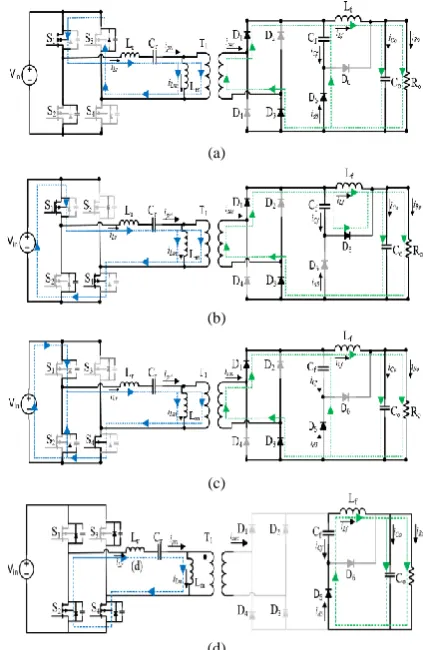
The analysis of the proposed converter is analyzed with ideal components in this paper. There is a dead zone (tdead) in each cycle to prevent two arms turned on at the same time, causing a short circuit, as shown in Fig. 3. According to the switching of the switches at steady state, it is divided into eight different modes, as shown in Fig. 4. Since the positive and negative half-cycle modes are the same, only four of them were described below. Fig. 5 shows the equivalent circuit from mode 1 to mode 4. Different modes have different resonant frequency.
According to the following formula calculates LLC resonant frequency:
𝑓𝑟1=2𝜋√𝐿1
𝑟𝐶𝑟 (1)
𝑓𝑟2=2𝜋√(𝐿1
𝑟+𝐿𝑚)𝐶𝑟 (2)
Since the secondary side auxiliary circuit participates resonance, the resonant frequency expressed by:
𝑓𝑟= 1
2𝜋√(𝐿𝑟+𝐿𝑚+𝑛2𝐿𝑓)∗𝐶𝑟𝐶𝑓 (3) (3)
Figure 3. Key waveforms of the proposed converter.
(a)
(b)
(c)
(d)
Figure 4. Pattern analysis of the proposed converter. (a) Mode1 (t0≦ t<t1) (b) Mode2 (t1≦t<t2) (c) Mode3 (t2≦t<t3) (d) Mode4 (t3≦t<t4). 𝛂
Mode 1 [t0, t1]
Switch S1 is turned on, S2, S3, S4 are turned off, Ipri rises from zero, Lr, Cr stores energy, diodes D1 and D2 turned on, Lf, Cf start energy storage, when ICf is less than Id5, diode D5 turned on, D6 turned off, because D5 was turned on, the current will countercurrent to Cf, causing Cf to discharge.
Mode 2 [t1, t2]
The switches S1 and S4 turned on, S2 and S3 turned off, Lr and Cr resonate and transfer energy to the secondary side, and the diodes D1 and D2 turned on. When ICf is equal to ID5, the diode D5 turned off, and D6 turned on, Cf Charging. The relevant formula is as follows, using Fourier transformer:
𝐼𝑝𝑟𝑖(s) =
𝑉𝑖𝑛 𝑠
𝑠𝐿𝑟+𝑠𝐶𝑟1
(4)
𝐼𝐷_𝑏𝑖𝑑(s) =𝑛𝐼𝑠𝑜−𝑠2𝐿𝑉𝑖𝑛
𝑟+𝐶𝑟1 (5)
𝐼𝑝𝑟𝑖(t) =𝑉𝑖𝑛√𝐿√𝐶𝑟
𝑟 × sin
1
√𝐿𝑟𝐶𝑟𝑡 (6)
𝐼𝐷_𝑏𝑖𝑑(t) =
𝑉𝑖𝑛∙sin √𝐿𝑟𝐶𝑟1 𝑡−𝐿𝑟∙𝐼𝑜∙𝑛∙√𝐿𝑟𝐶𝑟1
𝐿𝑟∙√𝐿𝑟𝐶𝑟1 (7)
Mode 3 [t2, t3]
Switch S4 is turned on, S1, S2, S3 are closed, the voltage across the transformer is zero, iD_bidi is gradually reduced, D5 is turned on, because iD_bidi is gradually reduced, iCf, id5 are discharged, auxiliary circuits Cf, Lf release energy, make up the transformer A shortage of energy to supply the load.
Mode 4 [t3, t4]
The switches S2, S4 turned on, and S1, S3 are turned off, and the iD_bidi drops to zero due to the secondary freewheel. At this time, iCf and id5 are zero, and the diode D6 turned on. Since ipri is zero, second side no energy. Lf and Cf to release energy.
Figure 5. Equivalent circuit of proposed converter.
III. SIMULATION
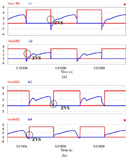
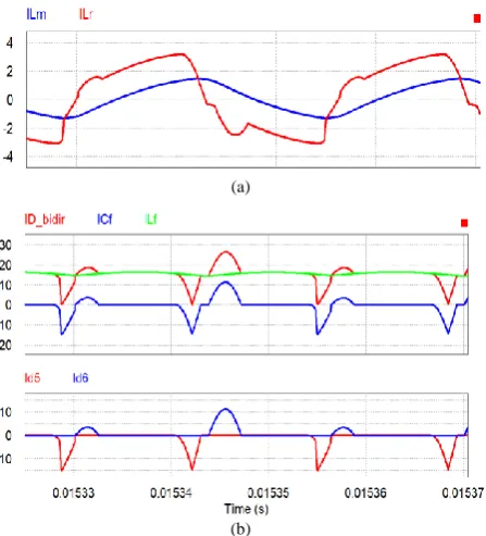
Fig. 6 shows the switches key waveforms. The rear arm of the traditional phase-shift converter is susceptible to the phase shift angle, resulting in large switching losses and cannot be zero voltage or zero current switching. However, the converter in this paper can improve this problem. Fig. 7 shows the waveform of the
primary and secondary currents. Although the conventional auxiliary circuit converter can improve the secondary side ringing phenomenon and reduce the circulating current, the circuit has no resonant component, and the energy transmission must be transmitted by a large triangular wave. The converter of this paper uses LLC resonance to transmit energy with less current during resonance and reduce circulating current loss. Compared the traditional phase shift converter, the efficiency increased by 8.86%. Compared the traditional phase shift full-bridge auxiliary circuit converter efficiency increased by 15%.
(a)
(b)
Figure 6. Switches waveform. (a) S1, S2 (b) S3, S4.
In order to compare the fairness, this paper takes the rated output power as the main reference, and performs efficiency analysis with the parameters of the fixed converter and the turns ratio of the slight drop.
The load efficiency analysis of the converter (PSFBLLC_auxi) and the traditional phase-shifted full-bridge LLC converter (PSFB_tr_LLC), the traditional phase-shifted full-bridge efficiency (PSFB_tr) and the traditional phase-shifted full-bridge auxiliary circuit (PSFB_tr_auxi) converter, As shown in Fig. 8 is the proposed converter primary side and secondary side current.
Table I shows the proposed converter parameters, Table II shows the parameters of the traditional full-bridge phase-shift auxiliary circuit converter, Table III shows the parameters of the traditional phase-shifted full-bridge LLC converter, and Table IV shows the traditional full-bridge phase-shift auxiliary circuit converter parameter.
Fig. 9 shows the efficiency of the converter and the other traditional phase-shifted full-bridge circuit
ZVS
ZVS
ZVS
converter. Fig. 10 shows the component loss analysis of the converter and the traditional phase-shifted full-bridge auxiliary circuit converter. The proposed converter greatly reduces losses.
(a)
(b)
Figure 7. Analog current waveforms. (a) primary side (b) secondary side.
Figure 8. Proposed converter current.
Figure 9. Converter efficiency comparison.
Figure 10. Loss analysis.
TABLEI. PARAMETERS OF THE PROPOSED CONVERTER
Parameter Value Parameter Value
Vin 400V Cr 51nF
Vo 48V Lf 60µH
Po 850W Cf 94µF
fs 38kHz Co 220µF
Lr 46µH n 8.33
TABLEII. PARAMETERS OF THE TRADITIONAL PSFBCONVERTER
Parameter Value Parameter Value
Vin 400V fs 25kHz
Vo 48V Co 220µF
Po 850W n 8.33
TABLEIII. PARAMETERS OF THE TRADITIONAL LLCCONVERTER
Parameter Value Parameter Value
Vin 400V Lr 225µH
Vo 48V Cr 180nF
Po 850W Co 470µF
fs 25kHz n 8.33
TABLEIV. PARAMETERS OF THE TRADITIONAL AUXILIARY CONVERTER
Parameter Value Parameter Value
Vin 400V Lf 20µH
Vo 48V Cf 660µF
Po 850W Co 940µF
fs 1kHz n 8.33
IV. CONCLUSION
The new full-bridge phase-shift LLC converter with auxiliary circuit proposed in this paper can effectively improve the characteristics of the traditional converter, and the full load efficiency can reach 98.51%. With the integration of the converter, the number of components can be reduced by half, thereby reducing conduction losses, switching losses and system costs, and greatly improving the overall efficiency of the circuit. The proposed converter achieves zero voltage or zero current switching, which allows it operate at high frequency,thus to reduce conduction loss and switching loss. The circuit 76%
78% 79% 81% 82% 84% 85% 87% 88% 90% 91% 93% 94% 96% 97% 99%
1 0 % 2 0 % 3 0 % 4 0 % 5 0 % 6 0 % 7 0 % 8 0 % 9 0 % 1 0 0 %
ef
ficie
n
cy
load
PSFBLLC_auxi PSFB_tr_auxi
PSFB_tr_LLC PSFB_tr
0 2 4 6 8 10 12 14 16
PSFBLLC_aux PSFB_tr_aux
L
O
SS
ES
(W
)
resonance is utilized to transfer energy to the secondary side with minimum current.
The proposed converter has the following advantages: 1) Zero voltage or zero current switching can reduce
switching losses.
2) Reduced circulating current and conduction loss, the efficiency is effectively increased.
3) The number of components is reduced by half, thus significantly reduces system costs.
4) The efficiency of the proposed converter at light load is 8.86% higher than that of the conventional converter with auxiliary circuit.
5) Reduced secondary side ringing and conduction loss.
6) The efficiency of the traditional LLC circuit at light load increases, which is improved by 2.54%. 7) The efficiency of proposed converter at full load
can reach 98.51%.
REFERENCES
[1] B. Gu, J. Lai, N. Kees, and C. Zheng, “Hybrid-Switching full-bridge DC–DC converter with minimal voltage stress of full-bridge rectifier, reduced circulating losses, and filter requirement for electric vehicle battery chargers,” IEEE Transactions on Power Electronics, vol. 28, no. 3, March 2013.
[2] C. Liu, et al., “High-Efficiency hybrid full-bridge–half-bridge converter with shared ZVS lagging leg and dual outputs in series,” IEEE Transactions on Power Electronics, vol. 28, no. 2, February 2013.
[3] H. Vu, D. Tran, and W. Choi, “A novel hybrid soft switching full-bridge PWM and full-full-bridge LLC converter for on-board battery
charger applications,” in Proc. IEEE 8th International Power Electronics and Motion Control Conference, 2016.
[4] J. Teng and W. Ou, “Hybrid zero-voltage and zero-current-switching phase-shift FULL-bridge converter,” master's thesis, Department of Electrical Engineering, National Sun Yat-Sen University, Kaohsiung, July 2013.
[5] H. Wang, “A pulse width modulated LLC type resonant topology adapted to width output voltage range,” in Proc. IEEE Applied Power Electronics Conference and Exposition, 2016.
[6] H. Wang and Z. Li, “A PWM LLC type resonant converter adapted to wide output range in PEV charging applications,” IEEE Transactions on Power Electronics, vol. 33, no. 5, May 2018. [7] H. Zou and H. Song, “Design of a snubber circuit for switching
power supply,” Sichuan Institute of Solid—State Circuits, China Electronics Technology Group Corp, PR China, Feb. 2008. [8] K. Murata and F. Kurokawa, “An interleaved PFM LLC resonant
converter with phase-shift compensation,” IEEE Transactions on Power Electronics, vol. 31, no. 3, March 2016.
[9] J. Lee, J. Kim, J. Kim, J. Baek, and G. Moon, “A high-efficiency PFM half-bridge converter utilizing a half-bridge LLC converter under light load conditions,” IEEE Transactions on Power Electronics, vol. 30, no. 9, September 2015.
Li-Ting Chou received the B.S. degree in electronic engineering from the National Chin-Yi University of Technology, Taiwan. She is currently studying master degree in electrical engineering at Yunlin University of Science and Technology, Taiwan. She is doing research about LLC power electronics converters.