255
Research JournalVolume 10, No. 31, Sept. 2016, pages 255–262
DOI: 10.12913/22998624/64019 Research Article
ALGORITHMS FOR TENNIS RACKET ANALYSIS BASED ON MOTION DATA
Maria Skublewska-Paszkowska1, Edyta Lukasik1, Jakub Smolka1
1 Institute of Computer Science, Lublin University of Technology, 36 Nadbystrzycka St., 20-618 Lublin, Poland, e-mail: [email protected], [email protected], [email protected]
ABSTRACT
Modern technologies, such as motion capture systems (both optical and marker-less), are more and more frequently used for athlete performance analysis due to their great precision. Optical systems based on the retro-reflective markers allow for tracking motion of multiple objects of various types. These systems compute human kinetic and kinematic parameters based on biomechanical models. Tracking additional objects like a tennis racket is also a very important aspect for analysing the player’s technique and precision. The motion data gathered by motion capture systems may be used for analysing various aspects that may not be recognised by the human eye or a video camera. This paper presents algorithms for analysis of a tennis racket motion during two of the most important tennis strokes: forehand and backhand. An optical Vicon system was used for obtaining the motion data which was the input for the algorithms. They indicate: the velocity of a tennis racket’s head and the racket’s handle based on the trajectories of attached markers as well as the racket’s orientation. The algorithms were implemented and tested on the data ob-tained from a professional trainer who participated in the research and performed a series of ten strikes, separately for: 1) forehand without a ball, 2) backhand without a ball, 3) forehand with a ball and 4) backhand with a ball. The computed parameters are gathered in tables and visualised in a graph.
Keywords: motion algorithms, tennis racket analysis, motion capture.
INTRODUCTION
Today the process of athlete training is sup -ported by modern technologies. Simply recording the players’ movements by a video camera may no longer be sufficient. Modern technologies can also be applied to tracking the movements of both the tennis player and the racket. They are expensive, but due to their accuracy they are more frequently used. Modern technologies are capable of moni-toring many useful biomechanical parameters in-dicating the athlete’s components of performance (e.g. angles, forces, ranges of motions, ground reaction forces). A motion capture system is an example of such technology. An optical system can record an athlete’s movements in a specially designed laboratory (or a shaded room) because of special infra-red cameras placed on the walls or
tripods that track the positions of markers attached to the human body, to a special suit or other objects (e.g. a tennis racket). Moreover, in modern motion capture systems the motion data may be combined with electromyography tests, providing synchro -nized information on muscle activity. However, the laboratory is not a natural environment for a player, so he or she may feel uncomfortable. The movements are limited to the walls. There is also a possibility of hitting and damaging the expensive cameras. To prevent such mishaps, a markerless motion capture system (e.g. Xsense) may be used while playing tennis on a court, which is an advan -tage. This kind of system computes the linear and angular motion usually based on readings from three gyroscopes and accelerometers installed in Inertial Measurement Units (IMUs). However, it is hard to track a tennis racket during such tests. Received: 2016.06.06
Advances in Science and Technology Research Journal Vol. 10 (31), 2016
256
This paper presents algorithms implemented in C++ designed for analysis of the tennis racket movement in two types of tennis strokes: forehand and backhand. These strokes are performed with and without a tennis ball. The recorded motion data is the source for the presented algorithms. The results obtained were used to compare these two types of strokes. The velocity of the tennis racket head and handle are analysed in both cas-es. The time at which the tennis racket reaches its greatest speed is indicated. The orientation of the racket is also analysed in both sagittal and axial planes. A professional trainer participated in the research and performed a series of ten strokes, separately for: 1) a forehand without a ball, 2) a backhand without a ball, 3) a forehand with a ball and 4) a backhand with a ball.
The racket movements (e.g. its velocity and orientation) while performing two most important tennis strokes provide information on the player’s technique. The aim of the analysis is to verify the proposed algorithms in practice and to verify the selected parameters of forehand and backhand strokes with and without a ball.
RELATED RESEARCH
Motion may be captured using professional equipment, but also Kinect devices [5]. Tracking the motion of the tennis racket together with the player’s movements has been studied in many papers [2, 3, 4, 9, 12, 13, 14, 15]. Three aspects of the racket are analysed: its velocity, swing and orientation. Both motion capture systems (optical and markerless) and video cameras are used for the research.
The motion and pose in 3 dimensions were computed from a video recording [4]. This meth -od also allows for computing racket performance. The swing of the racket was investigated in [2]. The speed of a tennis racket (as well as that of a golf club and a baseball bat) was analysed using 3-dimentional images obtained from two cam -eras. Reflective tape was placed on the elbow, around the wrist and around the racket’s handle in two places. The maximum effort (both in stand -ing and sitt-ing positions) was calculated for each swing. The swing speed was approximately con -stant during the test.
Tracking a tennis racket using a markerless system (based on multiple cameras) and a visual hull is presented in [3]. Views of a tennis racket
were recorded and segmented into binary images. The racket’s shape was obtained. The visual hull of the racket was created using the intersection of the volume of space formed by back-projecting the silhouettes from all input views.
In [11] the velocity of the tennis racket was calculated based on a monochrome recording made using a high-speed camera.
The Vicon system and a model consisting of sixty retro-reflective markers used to study the player’s biomechanical parameters while serving on a full size court is presented in [14]. Three 7-millimetre retro-reflective markers were attached to the tennis racket so that its velocity could be measured. An overall biomechanical analysis was performed. The orientation of the racket was expressed by its rotation. Twenty-two Vicon system cameras were used to study the ki -nematics of the player, racket and the tennis ball. Serving was divided into two groups: correct serves and service faults [12]. The racket’s ve -locity was estimated in [13]. The timing of peak forward racket velocity, considered critical to ac -curacy in the first serve, was one of the results. The arm mechanics, racket kinematics, impact location and ball speed in the tennis serve were studied in [15].
The influence of three various rackets on the shoulder net joint movements of tennis players is presented in [1]. Six cameras of the Eagle motion analysis system were used. The framerate was set at 256 fps. While serving, the racket and domi -nant upper limb kinematics were captured. Three spherical reflective markers were attached to the racket’s head frame: two at the mid-height of both racket-face sides to determine the centre of the racket-face and one at the top of the handle. Mo-ments, powers and rotations were calculated for each racket while serving.
The joint forces and torques were calculated using recordings from 12 Vicon system cameras with a frequency set at 300 Hz [6]. The player had 38 retro-reflective markers attached to the body. Five markers were attached to the tennis racket. The hand and the racket were assumed to be one segment. The relationships between segmental angular momentum and ball velocity between the following events-ball toss, maximal elbow flex -ion, racket lowest point, maximal shoulder exter -nal rotation, and ball impact-were studied in [7]. Also five markers were attached to the racket.
ad-257
dition, the moment of inertia, swing speed andvelocity of the rod using 12 cameras of the Mo -tion Analysis Corpora-tion mo-tion capture system were determined [9]. Two markers were attached to the rod base and rod tips. The results indicate that there is a relationship between swing speed and moment of inertia.
In the research presented above in which an optical system was used, reflective markers were attached to the racket. The number varied from three to five. Very often reflective tape was placed on the racket’s handle. All research focuses main-ly on the biomechanical anamain-lysis of the body, while the racket is an additional factor. Most pa -pers analysed the serve.
There is a lack of racket’s movements analy -ses while performing tennis strokes, especially an analysis focusing on the forehand and back-hand. There is a lack of implemented algorithms for determining the parameters needed for tennis racket motion analysis. The research presented in this paper concerns an analysis of a tennis racket which has seven retro-reflective markers attached. The markers define the overall shape of the racket. The research also includes a more precise analysis based on the described algo-rithms which are implemented in C++. Two basic strokes (forehand and backhand) are taken into consideration. The research is performed with a Babolat tennis racket.
METHOD
One left-handed 32 year-old tennis coach was the participant in this study. He was 192 cm tall and weighed 86 kg. He signed the ethical ap -proval form for this research.
A passive optical motion capture system was used to track the participant and the racket while performing tennis strokes at the Laboratory of Motion Analysis and Interface Ergonomics at the Lublin University of Technology in Poland where interdisciplinary tests are performed [10]. The research was conducted in a shaded room (without windows) so that no additional reflec -tions appeared, which might have affected the quality of the data obtained. The motion capture system consisted of: eight NIR T40S cameras operating in near infrared, two reference video Bonita cameras, a Giganet hub collecting data, a desktop computer and a set of accessories (e.g. markers, a calibration wand, double-sided tape).
The system recorded the positions of the markers placed on the subject’s body (each marker must be seen by at least two cameras). The reference video may be used both for data post-processing and for generating video files with a biomechanical model overlay. The equip -ment was supplied with Vicon’s Nexus 2.0 soft -ware, used for system calibration, data recording and data processing.
Experimental procedure
The participant was prepared for the experi -ment according to the Plug-in Gait Model [8]. 39 retroreflective markers were attached to the participant using hypoallergenic double-sided tape as specified in the model. This model al -lows for calculating angles, torques and forces in a subject’s joints. Each participant was mea -sured for the purpose of creating and scaling a new subject in Nexus software. The measured dimensions are: height, weight, leg length, arm offset, knee, ankle, elbow and the thickness of both hands. The subject’s calibration was per -formed as the next step in preparation. The par -ticipant stood in a “motorbike” pose which was captured. Apart from calibration, this procedure is important because it verifies the markers’ vis -ibility and placement.
The participant was told to perform two separate strokesstrikes, forehand and backhand, while running and avoiding a bollard placed on the floor. Because the participant was running, the strokes were more natural than hitting the ball from a standing pose. At first ten forehand strokes without a ball were performed, followed by ten backhand strokes without a ball. Next, these ex -ercises were repeated with a ball. The participant hits a ball which is caught by a special net.
Tracking the racket
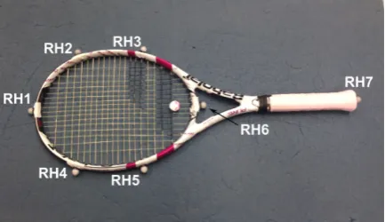
The racket was tracked during the research. Seven retro-reflective markers were attached to the racket according to the scheme presented in Figure 1. They allow one to reconstruct the shape of the racket. The markers were used for analys -ing the racket’s movement.
Post-processing
Advances in Science and Technology Research Journal Vol. 10 (31), 2016
258
using interpolation methods, data cleaning (e.g. deleting all unlabelled markers) and applying the Plug-in-Gait model (only for human body). A new subject was created for the racket. It consist -ed of seven markers. The post-process-ed record -ings were exported as C3D files. These files were used for further analysis. The files were processed by the authors’ own piece of software created in C++ using the Biomechanical toolkit (b-tk) and Eigen libraries.
Algorithms
The first algorithm calculates the velocities in frames for the particular marker’s coordinates. The time between two frames is the inverse of the markers frequency, set prior to the motion capture session. A Euclidean metric is used for computing the distance between the marker’s positions in two consecutive frames. Then, the array of velocities is filled in with the computed values. The results are expressed in millimetres per second. A pseudo code of the above algorithm is presented in Figure 2.
The second algorithm calculates the inclina -tion values of the angle of the vector defined by the two markers to reference plane in R3. The in -put parameters of the algorithm are the two spe -cific markers and the names of the coordinates
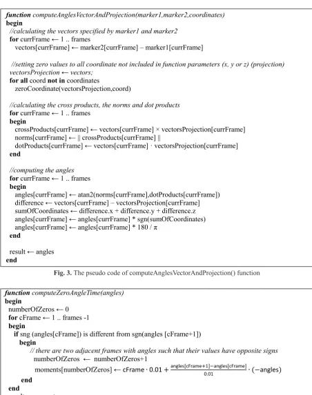
designating the plane (i.e. x and y, or x and z, or y and z). The angle values are determined in each frame of the recording. The results are placed in an array of size corresponding to the length of the analyzed recording. They show the change of the angle between the vector and its projection. The principle of the algorithm is: (1) to calculate the cross product of the 3D vector and its orthogonal projection, (2) to calculate the norm of the cross product (i.e. the value proportional to the sine of the angle between vectors) and (3) to compute the dot product (i.e. the value proportional to the co -sine of the angle between vectors). The next step is to use the atan2 function, which produces an angle value within the range of [0, pi] (the range is limited because the norm is non-negative). In order to determine whether the vector is pointing above or beneath the plane, the following calcu -lations are performed: (1) the difference between the input vector and its projection, (2) the sum of the coordinates of the difference is calculated. The sign of this sum is assumed to be the sign of the angle. A positive value indicates the vector’s pointing above the plane, and a negative value – below the plane. A pseudo code of the above algorithm is presented in Figure 3.
The next algorithm determines the moments in time at which the value of the supplied angles (angles between vectors and their projection) equals zero. The inputs are the angles in consecu -tive frames. The adjacent two frames in which the angles have opposite signs are found. Then, the moment when the angle reaches zero is calculated using linear interpolation. The result is an array with the calculated moments within the entire re -cording. A pseudo code of the above algorithm is presented in Figure 4.
In Figure 4 an assumption is made that the interval between two consecutive frames is set to 0.01 second. It is due to fact that the system frequency was set to 100 Hz.
Fig. 1. Tennis racket with seven markers attached
Fig. 1. Tennis racket with seven markers attached 3.5. Post-processing
Each 3D recording was post-processed using the Vicon Nexus software. The process consisted of four main steps: marker labelling, gap filling using interpolation methods, data cleaning (e.g. deleting all unlabelled markers) and applying the Plug-in-Gait model (only for human body). A new subject was created for the racket. It consisted of seven markers. The post-processed recordings were exported as C3D files. These files were used for further analysis. The files were processed by the authors’ own piece of software created in C++ using the Biomechanical toolkit (b-tk) and Eigen libraries.
3.6. Algorithms
The first algorithm calculates the velocities in frames for the particular marker’s coordinates. The time between two frames is the inverse of the markers frequency, set prior to the motion capture session. A Euclidean metric is used for computing the distance between the marker’s positions in two consecutive frames. Then, the array of velocities is filled in with the computed values. The results are expressed in millimetres per second. A pseudo code of the above algorithm is presented in Fig. 2.
Fig 2. The pseudo code of computeVelocity() function
function computeMarkerVelocity(coordinates)
begin
//calculating time between two frames
time←1/frequency;
for currFrame ← 1 .. frames -1 begin
distance ← EuclideanMetric (coordinates[currFrame+1], coordinates[currFrame]) velocity[currFrame] ←distance/time
end
result←velocity end
The second algorithm calculates the inclination values of the angle of the vector defined by the two markers to reference plane in R3.The input parameters of the algorithm are the two specific markers and the names of the coordinates designating the plane (i.e. x and y, or x and z, or y and z). The angle values are determined in each frame of the recording. The results are placed in an array of size corresponding to the length of the analyzed recording. They show the change of the angle between the vector and its projection. The principle of the algorithm is: (1) to calculate the cross product of the 3D vector and its orthogonal projection, (2) to calculate the norm of the cross product (i.e. the value proportional to the sine of the angle between vectors) and (3) to compute the dot product (i.e. the value proportional to the cosine
259
Advances in Science and Technology Research Journal Vol. 10 (31), 2016RESULTS
Racket’s velocity
The velocity of a tennis racket’s head was calculated using the RH1 marker while the rack
-et’s handle velocity was calculated using the RH7 marker (Fig. 1). These two markers coordi -nates were parameters of the function shown in Figure 2. The results for the forehand (FH) are presented in Table 1. The results for the back -hand (BH) are gathered in Table 2. The racket’s of the angle between vectors). The next step is to use the atan2 function, which produces an angle value within the range of [0, pi] (the range is limited because the norm is non-negative). In order to determine whether the vector is pointing above or beneath the plane, the following calculations are performed:(1) the difference between the input vector and its projection, (2) the sum of the coordinates of the difference is calculated. The sign of this sum is assumed to be the sign of the angle. A positive value indicates the vector’s pointing above the plane, and a negative value –below the plane. A pseudo code of the above algorithm is presented in Fig. 3.
Fig. 3. The pseudo code of computeAnglesVectorAndProjection() function
function computeAnglesVectorAndProjection(marker1,marker2,coordinates)
begin
//calculating the vectors specified by marker1 and marker2
for currFrame ← 1 .. frames
vectors[currFrame] ← marker2[currFrame] – marker1[currFrame]
//setting zero values to all coordinate not included in function parameters (x, y or z) (projection)
vectorsProjection ← vectors; for all coord not in coordinates
zeroCoordinate(vectorsProjection,coord)
//calculating the cross products, the norms and dot products
for currFrame ← 1 .. frames begin
crossProducts[currFrame] ← vectors[currFrame] × vectorsProjection[currFrame] norms[currFrame] ← || crossProducts[currFrame] ||
dotProducts[currFrame] ← vectors[currFrame] · vectorsProjection[currFrame] end
//computing the angles
for currFrame ← 1 .. frames begin
angles[currFrame] ← atan2(norms[currFrame],dotProducts[currFrame]) difference ← vectors[currFrame] – vectorsProjection[currFrame] sumOfCoordinates ← difference.x + difference.y + difference.z angles[currFrame] ← angles[currFrame] * sgn(sumOfCoordinates) angles[currFrame] ← angles[currFrame] * 180 / π
end
result ← angles
end
The next algorithm determines the moments in time at which the value of the supplied angles (angles between vectors and their projection) equals zero. The inputs are the angles in consecutive frames. The adjacent two frames in which the angles have opposite signs are found. Then, the moment when the angle reaches zero is calculated using linear interpolation. The result is an array with the calculated moments within the entire recording. A pseudo code of the above algorithm is presented in Fig. 4.
Fig. 4. The pseudo code of computeZeroAngleTime() function
Fig. 3. The pseudo code of computeAnglesVectorAndProjection() function
function computeZeroAngleTime(angles)
begin
numberOfZeros ← 0 for cFrame ← 1 .. frames -1 begin
ifsng (angles[cFrame]) is different from sgn(angles [cFrame+1]) begin
//there are two adjacent frames with angles such that their values have opposite signs
numberOfZeros ← numberOfZeros+1
moments[numberOfZeros] ← cFrame∙0.01+angles[cFrame+0.011]−angles[cFrame]∙(−angles)
end
end
result←moments
end
In Fig. 4 an assumption is made that the interval between two consecutive frames is set to 0.01 second. It is due to fact that the system frequency was set to 100 Hz.
4. Results
4.1. Racket's velocity
The velocity of a tennis racket's head was calculated using the RH1 marker while the racket's handle velocity was calculated using the RH7 marker (Fig. 1). These two markers coordinates were parameters of the function shown in Fig. 2. The results for the forehand (FH) are presented in Table 1. The results for the backhand (BH) are gathered in Table 2. The racket's velocity for the strokes with (FH with ball and BH with ball) and without a ball (FH and BH)
are compared. The algorithm presented in Fig. 2 computes the velocity in millimetres per second. These values were converted into kilometres per hour.
Table 1. Tennis racket's velocity during forehand
Movement Mean(±SD) [km/h] Min value[km/h] Max value[km/h]
FH RH1 127.75 (±14.48) 114.56 152.35
FH RH7 43.62(±4.87) 40.24 55.96
FH_Ball RH1 105.96(±7.99) 88.90 115.60
FH_Ball RH7 38.95(±3.11) 32.66 42.68
Table 2. Tennis racket's velocity during backhand
Movement Mean(±SD) [km/h] Min value[km/h] Max value[km/h]
FH RH1 103.98 (±3.38) 96.32 108.38
FH RH7 27.41 (±1.30) 24.85 29.14
FH_Ball RH1 102.94 (±5.74) 94.40 110.48
FH_Ball RH7 27.19 (±2.15) 24.25 30.75
The tennis racket's motion analysis contains the comparison of times for which the velocities
of the racket's head and the racket's handle are the highest. The time differences for 40 strokes
Advances in Science and Technology Research Journal Vol. 10 (31), 2016
260
velocity for the strokes with (FH with ball and BH with ball) and without a ball (FH and BH) are compared. The algorithm presented in Fig -ure 2 computes the velocity in millimetres per second. These values were converted into kilo -metres per hour.
The tennis racket’s motion analysis contains the comparison of times for which the velocities of the racket’s head and the racket’s handle are the highest. The time differences for 40 strokes Table 1. Tennis racket’s velocity during forehand
Movement Mean(±SD)[km/h] Min value[km/h] Max value[km/h]
FH RH1 127.75 (±14.48) 114.56 152.35
FH RH7 43.62(±4.87) 40.24 55.96
FH_Ball RH1 105.96(±7.99) 88.90 115.60
FH_Ball RH7 38.95(±3.11) 32.66 42.68
Table 2. Tennis racket’s velocity during backhand
Movement Mean(±SD)[km/h] Min value[km/h] Max value[km/h]
FH RH1 103.98 (±3.38) 96.32 108.38
FH RH7 27.41 (±1.30) 24.85 29.14
FH_Ball RH1 102.94 (±5.74) 94.40 110.48
FH_Ball RH7 27.19 (±2.15) 24.25 30.75
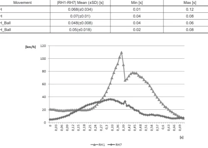
Table 3. The time differences for maximum velocities of racket’s head and racket’s handle
Movement |RH1-RH7| Mean (±SD) [s] Min [s] Max [s]
FH 0.068(±0.034) 0.01 0.12
BH 0.07(±0.01) 0.04 0.08
FH_Ball 0.048(±0.008) 0.04 0.06
BH_Ball 0.05(±0.018) 0.02 0.08
Fig. 5. The velocity of the tennis racket’s head and handle
(ten strokes for each of the analysed types) are presented in Table 3.
A graph representing a sample forehand stroke is depicted in Figure 5. The moment of impact is clearly visible. Just before the hitting the ball, the velocity of the racket’s head (RH1) decreases slightly, so that the strike can be per-formed with precision. At the moment of impact, the velocity of the racket’s handle (RH7) increas -es significantly. The wrist’s movements (which can be identified by the handle’s velocity) are cor -rect. This dependency is confirmed by the results shown in Table 4. The moment of the racket’s head maximum speed precedes the moment when the handle reaches its maximum speed.
Racket’s orientation
261
(this vector indicates whether the racket is paral-lel to the net), and 2) designated by the RH6 and RH1 markers (this vector indicates the tilt angle of the racket relative the floor surface). In both cases the computeAnglesVectorAndProjection() and computeZeroAngleTime() are used. The an -gles of the racket’s tilt in the tennis net plane are gathered in Table 4 together with the average ve -locity of the racket’s head and handle at the mo-ment of impact for all analysed strikes.
The results presented in Table 4 allow one to determine whether the racket’s orientation during impact was correct or not. The computed angles indicate that the racket’s head was slightly tilted towards the floor surface (the angle is negative).
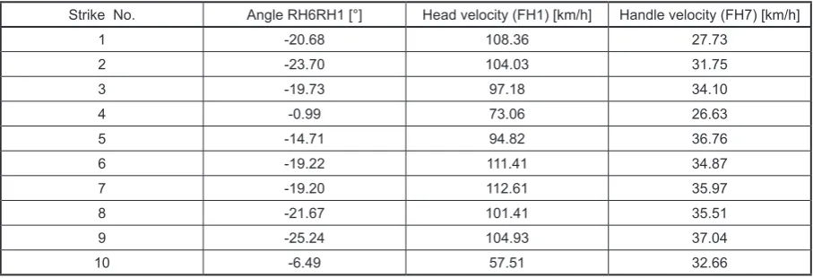
The results for ten forehand strikes are pre -sented in Table 5. They show the orientation of the axis of the rocket (RH6RH1 vector) relative to the floor surface, while the racket’s head was par -allel to the tennis net’s surface (RH2RH5 angle between the vector and the net surface is equal to zero).
The negative values indicate that the racket’s head was directed towards the floor. This is the correct orientation of the racket during impact. The occurrence of a parallel orientation of the racket to the net is also an evidence of proper stroke execution.
CONCLUSIONS
This paper presents algorithms for an analy -sis of tennis racket motion of the two most im -portant strokes: the forehand and the backhand. The tennis strokes were recorded using Vicon motion capture system consisting of eight NIR cameras. Seven retro-reflective markers were at -tached to the tennis racket for the purpose of this analysis. The results were generated by a piece of custom software created for the purpose of this research. The C3D file consisting of the mo -tion data was the input data to the program. The presented algorithms for computing a marker’s velocity and the racket’s angles in two surfaces were implemented in the software. They analyse the files and compute the necessary values.
The algorithm from Figure 3 is useful for the assessment of the stroke technique and determin-ing whether, durdetermin-ing its execution, the plane of the racket’s head is parallel to the plane of the tennis net. Another element of this analysis is to calcu-late the speed of the racket during the stroke us-ing algorithm from Figure 2. Usus-ing the algorithm in Figure 3, points in time are found in which the angle between the racket head and the reference plane is zero. At these points in time the speed of the racket’s head and its handle is calculated. Table 4. The tilt angle between the tennis racket and the net surface with the velocity of the racket’s head and handle
Movement Angle RH6RH1 Mean(±SD) [°] Head velocity Mean(±SD) [km/h] FH7 velocity Mean(±SD) [km/h]
FH -15.42 (±5.24) 110.38(±31.19) 31.19(±9.34)
BH -14.70(±1.82) 87.45(±3.34) 23.56(±1.63)
FH_Ball -17.16 (±7.73) 96.53(±17.79) 33.30(±3.64)
BH_Ball -11.89(±4.03) 101.05(±6.36) 20.11(±2.43)
Table 5. The tilt angle between the tennis racket and the net surface with the velocity of the racket’s head and handle for ten forehand strokes
Strike No. Angle RH6RH1 [°] Head velocity (FH1) [km/h] Handle velocity (FH7) [km/h]
1 -20.68 108.36 27.73
2 -23.70 104.03 31.75
3 -19.73 97.18 34.10
4 -0.99 73.06 26.63
5 -14.71 94.82 36.76
6 -19.22 111.41 34.87
7 -19.20 112.61 35.97
8 -21.67 101.41 35.51
9 -25.24 104.93 37.04
Advances in Science and Technology Research Journal Vol. 10 (31), 2016
262
Modern 3D technology is very helpful in train -ing tennis players. A motion capture system can be used for analysis of the captured athletes’ data. The system allows for the recording of a tennis player’s motion and his tennis racket’s movement. This article presents the parameters of the tennis racket’s motion calculated for the forehand and backhand strokes using the described algorithms. The strokes were performed with and without a ball. The velocity of the selected elements of the tennis racket’s head and handle was calculated. The orientation of the racket was also analysed during impact. Angles between (1) the racket and the floor surface and (2) the racket and the ten -nis net’s surface were calculated. The orientation of the racket is a crucial element of correct tennis stroke execution. From the presented analysis it is also possible to estimate the movement repeat -ability for a particular tennis player.
A comparison of the motion capture data and the presented algorithms is very useful for analysing a player’s technique while performing strokes. The motion capture system is very pre -cise, which results in the precision of the generat -ed results. Although, the results are not comput-ed while performing the exercises (post-processing is needed), they may provide valuable knowledge for the player and the trainer.
Acknowledgment
The research programme entitled “Biomechani-cal parameters of athletes in the individual exercises” based on the analysis of 3D motion data and EMG, realised in the Laboratory of Motion Analysis and Interface Ergonomics was approved by the Commis-sion for Research Ethics, No. 2/2016 dated 8.04.2016. The authors would like to thank the Student Sports Club Tennis Academy POL-SART for their support.
REFERENCES
1. Creveaux, T., Dumas, R., Hautier, C., Mace, P., Cheze, L., Rogowski, I.: Joint Kinetics to Assess the Influence of the Racket on a Tennis Player’s Shoulder. Journal of Sports Science and Medicine, 12, 2013, 259-266.
2. Cross, R., Bower, R.: Effects of swing-weight on swing speed and racket power. Journal of Sports Sciences, 24 (1), 2006, 23-30.
3. Elliott, N., Choppin, S., Goodwill, S.R., Allen, T.: Image-based visual hull of a tennis racket. 9th Conference of the International Sports
Engineer-ing Association (ISEA). Procedia EngineerEngineer-ing, 34, 2012, 877.
4. Elliott, N., Choppin, S., Goodwill, S. R., Allen T.: Markerless tracking of tennis racket motion using a camera. The 2014 conference of the International Sports Engineering Association. Elsevier. Procedia Engineering, 72, 2014, 344-349.
5. Kopniak, P.: Motion capture using multiple Kinet controllers. Przegląd Elektrotechniczny, 8, 2015, 26-29.
6. Martin, C., Bideau, B., Bideau, N., Nicolas, G., Delamarche, P., Kulpa, R., Flow E.: Analysis Dur-ing the Tennis Serve: Comparison Between Injured and Noninjured Tennis Players. The American Journal of Sports Medicine, 42, 2014, 2751-2760. 7. Martin, C., Kulpa, R., Delamarche, P., Bideau
B.: Professional tennis players’ serve: correlation between segmental angular momentums and ball velocity. Sports Biomechanics, 12 (1), 2013, 2-14. 8. Plug-in Gait Model, www.irc-web.co.jp/vicon\_
web/news\_bn/PIGManualver1.pdf
9. Schorah, D., Choppina, S., Jamesa, D.: Effect of moment of inertia and physical profile on restricted motion swing speed. The 2014 conference of the International Sports Engineering Association. Pro-cedia Engineering, 72, 2014, 593-598.
10. Skublewska-Paszkowska, M., Lukasik, E., Smol-ka, J., Milosz, M., Plechawska-Wojcik, M., Borys, M., Dzienkowski, M.: Comprehensive measure-ments of human motion parameters in research projects. In: Candel Torres I., Gomez Chova L., Lopez Martinez A. (Eds) 10th International Tech-nology, Education and Development Conference INTED, 6-9 March 2016, Valencia. Conference proceedings, IATED Academy, 2016, 8597-8605. 11. Washida, Y., Elliott, N., Allen, T.: Measurement
of main strings movement and its effect on tennis ball spin. The 2014 conference of the International Sports Engineering Associatio. Procedia Engineer-ing, 72, 2014, 557-562.
12. Whiteside, D., Elliott, B., Lay, B., Reid, M.:A kine-matic comparison of successful and unsuccessful tennis serves across the elite development pathway. Human Movement Science, 32, 2013, 822-835. 13. Whiteside, D., Elliott B., Lay, B., Reid, M.:
Coor-dination and variability in the elite female tennis serve. Journal of Sports Sciences, Vol. 33, No. 7, 2015, 675-686.
14. Whiteside, D., Elliott, B., Lay, B., Reid, M.: The Effect of Age on Discrete Kinematics of the Elite Female Tennis Serve. Journal of Applied Biome-chanics, 29, 2013, 573-582.