International Journal of Engineering
J o u r n a l H o m e p a g e : w w w . i j e . i r
An Intelligent Algorithm based Controller for Multiple Output DC-DC Converters
with Voltage Mode Weighting Factor
M. Sarvi*, S. Abedi
Department of Electrical Engineering, Imam Khomeini International University, Qazvin, Iran
P A P E R I N F O
Paper history:
Received 29 June 2013
Received in revised form 25 November 2013 Accepted12 December2013
Keywords:
Multiple Output DC-DC Converters Master-save Control
Genetic Algorithm Coupled Inductors Weighting Factor Method Cross Regulation
A B S T R A C T
Multiple output DC-DC converters are widely used in many applications such as aerospace, industrial and medical equipments. The purpose of this paper is to present an intelligent control system for the multiple output DC-DC converters. In order to perform this purpose, a double ended forward DC-DC converter with three output voltages (+5 V/ 50W, +15 V/ 45W and -15 V/ 15W) is considered and analyzed. The voltage mode weighting factor control system with Genetic Algorithm (GA) is performed on the considered DC-DC converter. Furthermore, a PID controller is utilized to minimize the total steady state error. The stability proofs of the system in presence of PID Controller have been analyzed.The results show that the GA weighting factors estimator improves the cross and output regulations in multiple output DC-DC converters. Simulation results verify and confirm the truth and accuracy of the proposed method
doi:10.5829/idosi.ije.2014.27.06c.07
1. INTRODUCTION1
Multiple outputs DC-DC converters are widely used in many applications such as aerospace, industrial and medical equipments. Furthermore, this type of DC-DC converters are used in SMPS as a power supply for power electronics applications [1]. In recent years, several types of DC-DC converters with different topologies and control systems have been presented and developed for different applications [1-6]. Generally, multiple output DC-DC converters are controlled in one of the most important of their outputs, and the rest of the outputs are intensively depend on the regulation of the main output. This main output is well known as master output in multiple outputs DC-DC converters and the others are called slave outputs. Actually, the main output is controlled precisely and the others left unattended. This kind of converters is well known as converters with Master-Slave outputs and in abbreviated form is called M-S converters [2].
In the M-S converters, the control loop is closed on master output (i.e. the most important one or the main output), while other auxiliaries are directly uncontrollable.
1*Corresponding Author Email:[email protected](M. Sarvi)
However, the cross regulation in the other auxiliaries are deeply dependent on variation of the input line and output loads. Thus, for having slave outputs with partly regulation, an additional control circuit to regulate the rest of the outputs should be considered. One way to keep these auxiliaries on their specification is using the post-regulators such as a buck-boost converters, magnetic amplifier or linear regulators. By using post-regulators in slave outputs, the feedback control circuit controls the freewheeling synchronous switches to keep output voltages within their specifications. Hence, the major problem in M-S DC-DC converters is the poor regulation of slave outputs against load and line variations [3-10].
The second type of multiple output DC-DC converters are converters which have good regulation on all of their outputs. Despite the amount of the regulation in slave outputs are not as well as main output regulation in M-S converters, all the outputs are controlled simultaneously. In this type of DC-DC converters all the outputs are participated in the control circuit by sampling circuits and affect directly on the effective duty cycle of PWM controller. Therefore, any changes in the load of each output affect directly on the control system [4-7].
is the converters which have good regulation on all of their outputs. In this paper, a forward topology with three outputs and weighted error voltage mode control approach is considered in order to present the proposed method (Figure 1). It is presented how an intelligent control system like genetic algorithm (GA) can be utilized for estimating weighting factors of the feedback circuits [11]. By using GA controller the most appropriate parameter of these factors can be calculated for the considered system during operation. Thus, there has been much more improved performance with GA tuned controller in compared with having fixed factors in term of good regulation. So, for setting weighting factors, GA controller is applied.
In addition, for improving regulation of the outputs and eliminating cross regulation between the outputs, coupled magnetic inductors are utilized in this forward DC-DC converter based on the transformer turn ratio. For designing control system, state space method is utilized [12]. Steady state and small signal analysis are performed on the proposed topology. Based on the analyses, a design procedure of the power circuit is generated, and implementation of the feedback controls is addressed. The beneficial of this approach compared with converters with post regulators is that at this converter the control system is more reliable because there is only one controller instead of having separate controller on each output. In addition, the number of control switches in converters with post regulators depends on the number of outputs while in weighted control approach only switching transistors on the primary circuit are needed. Finally, in order to investigate the accuracy and validity of the proposed method, a converter with three outputs (5V/50W, 15V/45W and -15V/15W) under operating of input voltage range from 18V to 40V dc with 28 V nominal voltage and a switching frequency of 50 kHz are considered and analyzed.
Figure 1. Multiple output forward DC-DC converter with coupled inductors
This paper is organized as follows: In section 2, used
topology of DC-DC converter is described. Operating principle and steady state analysis of the three-output forward DC-DC converter is presented in Section 3. Analysis of using magnetically coupled inductors in multi-outputs converters is presented in Section 4. In Section 5 the simulation results for some casesare analysed. Conclusions of this paper are presented in Section 6
2. DESCRIPTION OF THE PROPOSED TOPOLOGY
The proposed topology which is considered in this paper (Figure 1) consists of the following blocks:
2. 1. Power Stage
- High frequency transformer
- Switching transistors (consist of two switching MOSFETs)
- Output rectifiers
- Output filters
2. 2.Control Stage
- Intelligent control system - Modulator and PWM generator
One of the most important issues in multiple output DC-DC converters is the cross regulation. Indeed, the cross regulation is influenced by the circuit parasitizes of the forward converter [13].
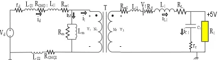
Therefore, all the circuit parasitic elements such as transformer leakage inductances and winding resistances, ON resistance of all semiconductor devices, junction inductance of the MOSFETS, etc. are considered. Figure 2 shows a simplified power stage model of Figure 1 incorporating all the major parasitic elements. Basically, the control circuits generate PWM signals for the two main switches in such a way that constant volt-second unidirectional pulses are produced.
Figure 2. Simplified model of Figure 1 incorporating all the major parasitic elements
regulation on the outputs against the input DC bus voltage variations and the output load changes. On the secondary side, all the output circuits are coupled with each other by using coupled magnetic inductors in order to eliminate cross regulations between the outputs.
To have a good output voltage regulation, it is essential that the weighted errors which directly influencethe effective duty cycle are changed simultaneously with variations ofline and load. Toperform this, the voltage error from each of the individual outputs is multiplied by a factor and summed up together to yield the total voltage error. This total error is subsequently passed through a PID controller to minimize the steady state error [11, 14-17]. Finally, it is given to the PWM modulator to generate the effective duty cycle. Since the factors multiplied to the voltage errors are so effective on the amount of output voltage regulations, they should be chosen very carefully. Therefore, a GA controller has been proposed for estimating these weighting factors to determine the best factors intelligently.
Generally, GA emulate the natural evolution processes of complex living creatures. GA employs the principal of “survival of the fittest” in its search process to select and generate individuals (design solutions) that are adapted to their environment (design objectives/constraints).
Therefore, over a number of generations (iterations), desirable traits (design characteristics) will evolve and remain in the genome composition of the population (set of design solutions generated in each iteration) over traits with weaker undesirable characteristics. Basically, GA consists of three main stages: Selection, Crossover
and Mutation.
The Selection operator selects chromosomes from
the current generation to be parents for the next generation. In this method, a few good chromosomes are used for creating new offspring in any iteration. Then, some bad chromosomes are removed and the new offspring is placed in their places. The rest of population migrates to the next generation without going through selection process.
Crossover is a genetic operator which is used to vary
the programming of a chromosome or chromosomes
from one generation to the next. The
crossover/reproduction operator computes two offspring for each parent pair given from the selection operator. The crossover operator is used to create new solutions from the existing solutions available in the mating pool after applying selection operator. This operator exchanges the gene information between the solutions in the mating pool. The most popular crossover selects any two solutions strings randomly from the mating pool and some portion of the strings is exchanged between the strings. The selection point is selected randomly. A probability of crossover is also introduced
in order to give freedom to an individual solution string to determine whether the solution would go for crossover or not.
Mutations are global searches. As with biological
systems, the mutation is manifested with a small change in the genetic string of the individuals. In the case of artificial genetic strings, the mutation is equal to a change in the elementary portion (allele) of the individuals’ code. The mutation takes place with characteristics different with those that the individuals had at the beginning, thosethat didnot possiblyexist in the population. From the point of view of problem optimization, it is equal to a change of the searcharea in the parameters space.
The fitness function for the genetic algorithm is considered corresponding to the output errors. It is expressed in the sum of the absolute terms of the relative errors as following:
Fitness Function = |e+ 5| + |e+ 15| + |e-15| (1) where, e+5is the +5 Voutput error, e+15is the +15 Voutput error and e-15is the -15 Voutput error.
3. OPERATING PRINCIPLE AND STEADY STATE ANALYSIS OF THE THREE-OUTPUT FORWARD DC-DC CONVERTER
In this section the steady state operation and state space analysis of the three-output forward DC-DC converter of the proposed toplogy is presented [18, 19].
For the steady state analysis, the following assumptions are made.
- The input and output DC voltages are constant. - The switching frequency is FS.
- The circuit is in the continuous conduction mode.
- The components have linear properties.
- The leakage inductances of transformer are considered.
- All the circuit parasitic elements are considered. - The turns ratio between coupled inductors are
equal to the transformer outputs turns ratio. - All the outputs are supplying their full loads. In steady state, each output circuits goes through two modes per cycle. Therefore, state space method is applied on these two modes.
3. 1. Mode 1: Q1,Q2,D1are ON and D2is OFF
0 < t < DTs On this mode switching transistors (Q1
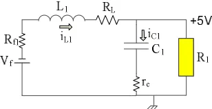
Figure 3. The equivalent circuit of the master output of the proposed converter at 0≤ ≤ .
Let’s consider the following simplifiers:
2 1
1
1eq rd Rw RONQ RONQ
R = + + + (2)
2 1 1
1eq LQ Ll LQ
L = + + (3)
L f W
eq R R R
R2 = 2 + 1 + (4)
2 1 2eq L Ll
L = + (5)
where, rdis the source resistance, Rw1 and Rw2are the primary and secondary winding resistances, respectively. Rf1 is the ON state resistance of D1. RONQ1 and RONQ2is the ON state resistance of switching MOSFETS, respectively. L11 and L22 are the primary and secondary leakage inductances, respectively. LQ1 and LQ2 are the MOSFETS leakage inductances, respectively. L1 is the output filter inductance and RL1 is resistance of the output filter inductance.
1 1
2 2 1 2 1 1 1
C L
eq L eq f C C
dV di
V R i L V V r C
dt dt
= + + + + (6)
1 1 1 1 1 C R V C i dt
dVC L o
-= (7)
Assuming that the magnetizing current is negligible and the magnetizing inductance is large enough, so
1
~i
id = (8)
where,
1 1 2
2 N V
N
V = (9)
1 1 2 1 N iL
N
i = (10)
Therefore: dt di N N L i N N R V V L eq L eq d 1 1 2 1 1 1 2 1
1= - - (11)
dt dV C R i R i i R
Vo= 1(L1- C1)= 1L1- 1 1 C1 (12)
where V1 and V2 are the primary and secondary voltages of the ideal transformer, respectively. iL1 is the output
filter inductance current, Vf is the forward voltage drop of diode, Vc1is the output capacitor voltage, rc1 is the ESR12 of the output capacitor, V
ois the main output voltage and ic1 is the output capacitor current.
Substituting (11) in(6) and (11) in(7), then it yields:
dt dV C r V V dt di L N N L i R N N R V N N C C C f l eq eq L eq eq d 1 1 1 1 1 2 2 1 2 1 1 2 2 1 2 1 1
2 ( ( ) ) ( ( ) )
+ + + + + + = (13) dt dV C R Ri dt di L N N L i R N N R V N N C L l eq eq L eq eq d 1 1 1 1 1 2 2 1 2 1 1 2 2 1 2 1 1 2 ) ) ( ( ) ) ( ( -= + -+ -(14)
Substituting (13) in(14) yields:
) ( ) ( )
( 1 1 1 1 1 1
1 1 1 1 1 1 1 R r C V R r C V i R r C R dt dV C f C C L C C + -+ -+ = (15)
Let’s consider:
eq eq
t N R R
N
R 2 1 2
1 2) ( + = (16) eq eq
t N L L
N
L 2 1 2 1
2)
( +
= (17)
Substituting (15) in(13) yields:
d t f C t C C t L C t t C t C L V N L N V R r L R V R r L R i R r L R R r R r R dt di 1 2 1 1 1 1 1 1 1 1 1 1 1 1 1 1 1 ) ( ) ( ) ) ( ( + + -+ -+ + + -= (18)
Substituting (15) in(12):
f C C C L C C
o rRr R i r R R V r R R V
V 1 1 1 1 1 1 1 1 1 1 1 1 + + + + + = (19) ú û ù ê ë é ú ú ú ú û ù ê ê ê ê ë é + -+ -+ + ú û ù ê ë é ú ú ú ú û ù ê ê ê ê ë é + -+ + -+ + + -= ú ú ú ú û ù ê ê ê ê ë é ¢ ¢ f d B C C t t C L A C C C t C t t C t C C L V V R r C R r L R N L N V i R r C R r C R R r L R R r L R R r R r R dt dVdt di 4 4 4 4 8 4 4 4 4 7 6 4 4 4 4 4 4 4 8 4 4 4 4 4 4 4 7 6 1 1 ) ( 1 0 ) ( ) ( 1 ) ( ) ( ) ( 1 1 1 1 1 1 1 2 1 1 1 1 1 1 1 1 1 1 1 1 1 1 1 1 1 1 1 1 (20) ú û ù ê ë é ú û ù ê ë é + + ú û ù ê ë é ú û ù ê ë é + + = ¢ ¢ f d D C C L C C C C o V V R r R V i R r R R r r R V 4 4 8 4 4 7 6 4 4 4 8 4 4 4 7
6 1 1
1 1 1 1 1 1 1 1 1 1 1
1 0 (21)
3. 2. Mode 2: Q1,Q2,D1 are OFF and D2 is ON
DTs<t<Ts On this mode switching transistors (Q1 ,
Q2) and the output rectifier (D1) are off. The equivalent circuit at this mode incorporating all of the circuit parasitic elements in master output is shown in Figure 4.
Figure 4. The equivalent circuit of the master output of the proposed converter atDTs< t < Ts
1 1 1
1dVdt i VR
C C = L - o (22)
dt dV C r V dt di L i R
Vf =- t2L1- L1 L1- C1- C1 1 C1 (23)
dt di C R L C R V i C R R R dt
dV f L L
L t C 1 1 1 1 1 1 1 1 1 2 1
1= + + + (24)
1 1 1 1 1 1 1 1 1 1 ) ( 1 )
(C L C C
C V R r C i R r C R dt dV + -+ = (25)
Substituting (25) in(23) and (25) in(22):
2 1 2 1 1 1
1 1
1 1
1( 1 1) 1( 1 1) 1
t C t C
L f
L C
L C L C L
R r R R R r
di R V
i V
dt L r R L r R L + +
= - -
-+ + (26)
1 1 1 1 1 1 1 1 1 C C L C C
o rRr R i r R R V
V + + + = (27) ú û ù ê ë é ú ú û ù ê ê ë é -+ ú û ù ê ë é ú ú ú ú û ù ê ê ê ê ë é + -+ + -+ + + -= ú ú ú û ù ê ê ê ë é ¢ ¢ f d B L C L A C C C L C L t C t C t C L V V L V i R r C R r C
R L r R
R R r L R R r R r R dt dVdt di 48 47 6 4 4 4 4 4 4 4 4 8 4 4 4 4 4 4 4 4 7 6 2 2 0 0 1 0 ) ( 1 ) ( ) ( ) ( 1 1 1 1 1 1 1 1 1 1 1 1 1 1 1 1 1 1 2 1 1 2 1 1 (28) ú û ù ê ë é ú û ù ê ë é + + = ¢ 1 1 1 1 1 1 1 1 1 2 C L C C C C o V i R r R R r r R V 4 4 4 4 8 4 4 4 4 7 6 (29)
By using space state averaging method, we have:
d V B B X A A BV X A
X~ = ~+ d -[( 1¢- ¢2) +( 1¢- 2¢)~d]~ (30)
d X C C X C
V~& = ~+( 1¢- 2¢) ~ (31)
where Xis the state vector and includes capacitor voltage and inductor current, A1¢ and A2¢are the state Amatrixes in modes 1 and 2, respectively. B1¢ and B2¢are the state
B matrixes in the modes 1 and 2, respectively. C1¢ and
2
C¢are the state C matrixes in the modes 1 and 2, respectively. The rest of the variables are defined as follows:
) 1 ( 2
1D A D
A
A= ¢ + ¢ - (32)
) 1 (
2
1D B D
B
B= ¢ + ¢ - (33)
) 1 (
2
1D C D
C
C= ¢ + ¢ - (34)
where, D is the effective duty cycle in the specified load on the output. For each output we can consider the above analysis. Therefore, control transfer function for each output of the forward topology with two switching transistors in continuous conduction mode can be derived as follows:
] ) [( ] ) ( ) [( ) ( ~ ~ 2 1 2 1 2 1 1 ) ( ) ( ) ( X C C V B B X A A A SI C d V F d S S o S -+ -+ -= = -(35)
The stability of the system is guaranteed by having three negative poles in the closed loop system described as follows:
After substitution of the component we have:
8 4 2 8 5 ) ( 10 835 . 1 10 447 . 3 10 435 . 9 10 963 . 1 ´ + ´ + ´ -´ -= S S S
FS (36)
The Transfer function of PID controller of the system is:
S S S 50 0.1 01
.
0 2+ +
(37)
So, the closed loop transfer function including PID controller is: 7 10 2 7 3 7 10 2 7 3 10 435 . 9 10 699 . 4 10 921 . 1 1962 10 435 . 9 10 718 . 4 10 925 . 1 1963 ´ + ´ + ´ + ´ + ´ + ´ + S S S S S S (38)
The poles of the closed loop transfer function are as follows: 002 . 0 , 10 7276 . 4 , 10 0676 .
5 3 3
2 3
1=- ´ P =- ´ P =
-P
The zeroes of the closed loop transfer function are: 002 . 0 , 10 8078 . 4 , 10 0 .
5 3 3
2 3
1=- ´ Z =- ´ Z =
-Z
balance its bad effect on the system.
4. ANALYSIS OF USING MAGNETIC COUPLED INDUCTORS
When we have identical voltages on a DC-DC converter, it is best condition to utilize coupled inductors in these outputs to omit cross regulation and ripple voltages. When outputs of DC-DC converter are coupled by using a common core for the inductors, giving the same volt-turns to these inductors is so important, because any unbalancing between the coupled voltages can cause a circulating current in the circuit and it leads to a big output ripple voltage. Therefore, on the outputs with the same absolute value voltages, coupled inductors with identical turns should be used. However, for other outputs with different voltages we should try to keep volt-turns index equal [13].
Hence, for aving a good response from magnetic coupled inductors on all the outputs, we can estimate the turns ratio between coupled inductors in similar to turns ratio between the secondary windings of the transformer. This estimation will help us to eliminate the cross regulation between the slave outputs and reduce the amount of ripple voltages. So we have:
1 3 1 2 1 3 1 2
N N N N N N N N
L L L
L = = = (39)
in which, NL1, NL2and NL3are the number of turns for output coupled inductors.
Therefore, after computing the amount of filter inductance on +5Voutput and specifying the number of turns for this output, NL1, NL2and NL3 will be determined simultaneously.
5. ANALYSIS OF THE SIMULATED RESULTS
In order to verify the improvements of the proposed method and positive effects of using GA controller in estimating weighting factors, the described DC-DC converter in previous sections and its control system are simulated under following specifications:
- Input voltage: Vd =18 to 40 V with 28 V nominal
- The first output: Vo1=5 V and 10 A - The second output: Vo2 =15 V and 3 A - The third output: Vo3 =-15 V and 1 A - Switching frequency: fs = 50 KHz - The number of GA population: N = 30 - The number of repetition: NR = 50
variables K1, K2, & K3 at GA are coded to solve string structures. Binary coded string having 1’s & 0’s are
mostly used. The length of string is usually determined according to the desired accuracyof the solution. Here, 10 bits are used to code each variable. We can use 8 bit & 4 bit also. Thereafter, select the random strings from the population to form the mating pool. In order to use roulette-wheel selection procedure, we calculate the average fitness of the population. Then, the mating pool strings are used in the crossover operation. The next step is to perform mutation on strings in the intermediate population. The resulting population becomes the new population. Here, we measure the population diversity by pair-wise Hamming distance among genotypes in the population environment. The whole process is coded in MATLAB & after running the program we get the optimized values of K1, K2& K3. All the parameter values which have been applied to GA are shownin Table 1.
The simulations are performed in MATLAB SIMULINK environment under three following conditions:
- Open Loop Control
- Close Loop Control by PID Controller and using constant weighting factors
- Utilizing of GA weighting estimator controller
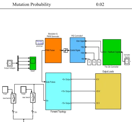
The block diagram of the proposed converter is shown in Figure 5.
TABLE 1. The GA parameters
Parameter Value
Population size 50
Iteration 30
Crossover Probability 0.8
Mutation Probability 0.02
Figure 5. The block diagram of the simulated model
Discrete, Ts = 5e-008 s
powergui
Timer4 Timer1
Feedback Signals Error
The GA Controller
Scope1
3 Sampled Signals
Error Signal
<Kp>
<Kd>
<Ki> Control Signal
PID Controller1
4
Output Voltages
+5 V
+15 V
-15 V
Output Loads In
PWM Pulses
Modulator & PW M Generator
g 1
2
Ideal Switch4
g 1
2
Ideal Switch1
Gate Pulses
Vin
+5v Output
+15v Output
-15v Output
Forward Topology
Demux Ki Kd Kp
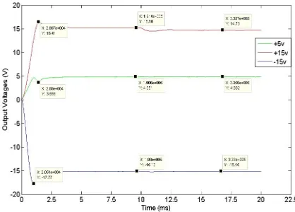
5. 1. Condition 1: Open Loop Control In this condition, there is no control system, and open loop condition is considered and simulated. Figure 6 shows the simulation results of this condition under nominal input voltage and nominal output loads. This figure shows that +5 v output has been converged around +4.87 volt and other auxiliaries have been converged to +15.37 and -15.31 volt in the steady state operation, while there is no any controller and it is acceptable because the effective duty cycle is constant under this condition.
5. 2. Condition 2: Close Loop Control by PID Controller and Using Constant Weighting Factors
In this condition, closed loop control system with a PID controller is developed based on the state space averaging method and by using transfer function which is derived in section III of this paper. The PID coefficients are determined for the studied DC-DC converter by using trial and error. In addition constant weighting factors are multiplied to the voltage errors in the feedback circuits and discrete inductors are placed in each output. Furthermore, at this condition, magnetic coupled inductors are utilized in the proposed topology in order to eliminate the cross regulation between the outputs especially at the moment that line and load change suddenly. Figures 7-10 demonstrate this condition under line (input voltage) and load step. Line and load step are investigated on all outputs by changing line from 25 volt to 35 volt (Figures 6 and 7) and load from 50% to 100% (Figures 8 and 9) at t=0.01 sec.
5. 3. Condition 3: Utilizing of GA
WeightingEstimator Controller Figures 11-14
demonstrate how the GA controller improve the amount of regulation on all outputs by determining of weighting factors while all the major circuit parasitic elements are considered in the mentioned forward converter. at this condition, magnetic coupled inductors are too utilized.
Figure 6. Output voltages without any controller while input voltage is 28 V.
Figure 7. Output voltages with constant weighting factors and PID controller while input voltage changes from 25 V to 35 V.
Figure 8. Output voltages with constant weighting factors and PID controller while load on +5 Voutput changes from 50% to 100%.
Figure 10. Output voltages with constant weighting factors and PID controller while load on -15 v output changes from 50% to 100%.
Figure 11. Output voltages with GA weighting factors estimator and PID controller while input voltage changes from 25 V to 35 V.
Figure 12. Output voltages with GA weighting factors estimator and PID controller while load on +5 v output changes from 50% to 100%.
Figure 13. Output voltages with GA weighting factors estimator and PID controller while load on +15 Voutput changes from 50% to 100%.
Figure 14. Output voltages with GA weighting factors estimator and PID controller while load on -15 V output changes from 50% to 100%.
The amounts of regulations of the forward multiple output converters are shown in Tables 2-5 for load and input voltage variations. As it seen in these tables, the regulations of the outputs are compared in two below cases:
Case 1:PID controller with constant weighting factors is utilized
Case 2: PID controller with coupled inductors and GA estimator are performed.
TABLE 2. Output voltage regulation while input voltage changes from 25 V to 35 V
Outputs specifications
Regulation (%) before line step Regulation (%) before line step
with constant weighting factors
with GA weighting factors estimator
with constant weighting factors
with GA weighting factors estimator
+5V/10A 5.4 0.8 6.2 0.9
+15V/3A 1.6 0.06 1.7 0.2
-15V/1A 0.4 0.8 0.7 1.8
TABLE 3. Output voltage regulation while load changes at +5 volt output from 50% to 100%
Outputs specifications
Regulation (%) before load step Regulation (%) after load step
with constant weighting factors
with GA weighting factors estimator
with constant weighting factors
with GA weighting factors estimator
+5V/10A 5.2 3.5 6.4 1
+15V/3A 0.5 2 1.7 0.7
-15V/1A 2.5 0.9 0.7 0.8
TABLE 4. Output voltage regulation while load changes at +15 volt output from 50% to 100%
Outputs specifications
Regulation (%) before load step Regulation (%) after load step
with constant weighting factors
with GA weighting factors estimator
with constant weighting factors
with GA weighting factors estimator
+5V/10A 6.8 3 3.8 1.2
+15V/3A 2 1.2 1 1.8
-15V/1A 3.2 0.8 1.1 1
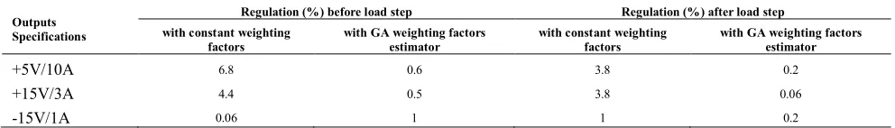
TABLE 5. Output voltage regulation while load changes at -15 volt output from 50% to 100%
Outputs Specifications
Regulation (%) before load step Regulation (%) after load step
with constant weighting
factors with GA weighting factors estimator with constant weighting factors with GA weighting factors estimator
+5V/10A 6.8 0.6 3.8 0.2
+15V/3A 4.4 0.5 3.8 0.06
-15V/1A 0.06 1 1 0.2
6. CONCLUSION
In this paper a PID controller with a GA estimator for weighting factor approach is proposed to a three output forward DC-DC converter. The PID coefficients have been estimated by using transfer function between output voltage (Vo) and input signal (DC-DC converter duty cycle, d(s)) that has been produced through state space averaging method. For multiplying the optimized weighting factors, a genetic algorithm controller is utilized. In order to investigate the accuracy and truth of the proposed method, some conditions were considered and simulated.Results were illustrated that the GA estimator beside the main PID controller can improve the output regulation in multiple output DC-DC converters by changing input line and output loads at the specified instances. As a result, optimal weighting factors are obtained and good closed-loop control system performance is achieved. Moreover, it is shown that the genetic algorithm provides a simple, efficient
and accurate approachto tune weighting factors in the control system. Also, it is shown that coupled magnetic inductors are a major section of a multiple output DC-DC converter to improve the cross regulation and keep the outputs in their specification. Tothis end, it is described that the number of turns of the coupled magnetic inductors and the turn ratio of the main transformer should be identical to have excellent regulation on the auxiliary outputs.
7. REFERENCES
1. Reddy, J., Bhuvaneswari, G. and Singh, B., "A single DC-DC converter based multiple output smps with fully regulated and isolated outputs", in INDICON, Annual IEEE, (2005), 585-589. 2. Pan, S. and Jain, P., "A precisely-regulated multiple output
forward converter with automatic master-slave control", in Power Electronics Specialists Conference, PESC'05. IEEE 36th, IEEE. (2005), 969-975.
Electronics, IEEE Transactions on, Vol. 18, No. 2, (2003), 648-658.
4. Barrado, A., Olias, E., Lazaro, A., Pleite, J. and Vázquez, R., "PWM-PD multiple output DC/DC converters: Operation and control-loop modeling", Power Electronics, IEEE Transactions on, Vol. 19, No. 1, (2004), 140-149.
5. Barrado, A., Olias, E., Roldan, A. and Pleite, J., "Control-loop modeling of the pwm-pd multiple output DC/DC converters", in Power Electronics Specialists Conference, PESC 31st Annual, IEEE. Vol. 1, (2000), 395-400.
6. Chen, Q., Lee, F.C. and Jovanovic, M., "Analysis and design of weighted voltage-mode control for a multiple-output forward converter", in Applied Power Electronics Conference and Exposition, APEC'93. Conference Proceedings, Eighth Annual, IEEE. (1993), 449-455.
7. Perry, A.G., Feng, G., Liu, Y.-F. and Sen, P.C., "A design method for pi-like fuzzy logic controllers for DC–DC converter", Industrial Electronics, IEEE Transactions on, Vol. 54, No. 5, (2007), 2688-2696.
8. Chen, Y.-T., Chen, D.Y. and Wu, Y.-P., "Control-loop modeling of multiple-output feedback of forward converters", IEEE
Transactions on Power Electronics, Vol. 8, No. 3, (1993),
320-328.
9. FRED, C., "Current-mode control for multiple-output converters", IEEE Transactions on Aerospace and Electronic
Systems, Vol. 32, No. 4, (1996).
10. Jamerson, C.L., "Post-regulation techniques for 100 khz to 300 khz multiple-output pwm supplies", in High-Frequency Power Conversion Conf.(HFPC) Proc. (1989), 260-273.
11. Xiaofang, W., Min, W., Liyu, O. and Qingsong, T., "The application of GA-PID control algorithm to DC-DC converter",
in Control Conference (CCC), 29th Chinese, IEEE. (2010), 3492-3496.
12. Erickson, R.W. and Maksimovic, D., "Fundamentals of power electronics", Springer, (2001).
13. Lo, Y.-K., Song, T.-H. and Yen, S.-C., "Analysis and design of a two-output forward converter with an output voltage objective function", in Industrial Technology, ICIT IEEE International Conference on, (2006), 540-545.
14. Joseph, X.F., Pushpakumar, S., Dominic, D.A. and Prabha, D.M.S.R., "Design and simulation of a soft switching scheme for a DC-DC boost converter with pi controller", International
Journal of Engineering (IJE), Vol. 4, No. 4, (2010), 285.
15. Kapat, S. and Krein, P.T., "Formulation of pid control for dc–dc converters based on capacitor current: A geometric context",
Power Electronics, IEEE Transactions on, Vol. 27, No. 3,
(2012), 1424-1432.
16. Li, H. and Ye, X., "Sliding-mode PID control of DC-DC converter", in Industrial Electronics and Applications (ICIEA), the 5th IEEE Conference on, IEEE. (2010), 730-734.
17. Rabbani, M., Maruf, H.M., Ahmed, T., Kabir, M. and Mahbub, U., "Fuzzy logic driven adaptive pid controller for pwm based buck converter", in Informatics, Electronics & Vision (ICIEV), International Conference on, IEEE. (2012), 958-962.
18. Barry, N. and Daly, B., "Coupled magnetic amplifiers in forward converter topologies", IEEE Transactions on Power
Electronics, Vol. 14, No. 1, (1999), 168-176.
19. Nair, M. and Sankaran, R., "Simulation and experimental verification of closed loop operation of buck/boost DC-DC converter with soft switching", International Journal of
Engineering-Transactions C: Aspects, Vol. 25, No. 4, (2012),
267.
An Intelligent Algorithm based Controller for Multiple Output DC-DC Converters
with Voltage Mode Weighting Factor
M. Sarvi, S. Abedi
Department of Electrical Engineering, Imam Khomeini International University, Qazvin, Iran
P A P E R I N F O
Paper history:
Received 29June2013
Receivedin revised form25November 2013 Accepted12 December2013
Keywords:
Multiple Output DC-DC Converters Master-save Control
Genetic Algorithm Coupled Inductors Weighting Factor Method Cross Regulation
هﺪﯿﮑﭼ
لﺪﺒﻣ يﺎﻫ
DC-DC
راﺮﻗهددﺎﻔﺘﺳادرﻮﻣﯽﮑﺷﺰﭘتاﺰﯿﻬﺠﺗوﯽﺘﻌﻨﺻ،ﺎﻀﻓاﻮﻫيﺎﻫدﺮﺑرﺎﮐزايرﺎﯿﺴﺑردهدﺮﺘﺴﮔرﻮﻃﻪﺑ
ﯽﻣ ﺪﻧﺮﯿﮔ
.
لﺪﺒﻣياﺮﺑﺪﻨﻤﺷﻮﻫلﺮﺘﻨﮐﻢﺘﺴﯿﺳﮏﯾﻪﺋاراﻪﻟﺎﻘﻣﻦﯾازافﺪﻫ يﺎﻫ
DC-DC
ﺖﺳاﯽﺟوﺮﺧﺪﻨﭼ
.
يﺎﺘﺳاررد
لﺪﺒﻣﮏﯾ،فﺪﻫﻦﯾامﺎﺠﻧا
DC-DC
ﯽﺟوﺮﺧﻪﺳﺎﺑ ﻪﯾﻮﺳوددراورﻮﻓ
) 5 +
ﺖﻟو
/ 50
،تاو
15 +
ﺖﻟو
/ 45
وتاو
15 -
ﺖﻟو
/ 15
تاو
(
وبﺎﺨﺘﻧا ﻠﯿﻠﺤﺗ ﺖﺳاهﺪﺸ
.
لﺪﺒﻣيورﺮﺑﮏﯿﺘﻧژﻢﺘﯾرﻮﮕﻟاﻂﺳﻮﺗيژﺎﺘﻟودﻮﻣﯽﻧزوﺐﺋاﺮﺿلﺮﺘﻨﮐﻢﺘﺴﯿﺳ
DC-DC
هﺪﺷيزﺎﺳهدﺎﯿﭘﺮﻈﻧدرﻮﻣ ﺖﺳا
.
هﺪﻨﻨﮐلﺮﺘﻨﮐرﻮﻀﺣردﻢﺘﺴﯿﺳيراﺪﯾﺎﭘتﺎﺒﺛا
PID
ﻪﺘﻓﺮﮔراﺮﻗﯽﺳرﺮﺑدرﻮﻣ
ﺖﺳا
.
ﯽﻣنﺎﺸﻧﺞﯾﺎﺘﻧ ﻦﯿﻤﺨﺗناﻮﻨﻋﻪﺑﮏﯿﺘﻧژﻢﺘﯾرﻮﮕﻟاﻪﮐﺪﻨﻫد
لﺪﺒﻣردارﯽﺟوﺮﺧژﺎﺘﻟوﻢﯿﻈﻨﺗﯽﻧزوﺐﺋاﺮﺿﺮﮔ يﺎﻫ
DC-DC
ﯽﻣدﻮﺒﻬﺑﯽﺟوﺮﺧﺪﻨﭼ ﺪﺸﺨﺑ
.
ﻪﯿﺒﺷﺞﯾﺎﺘﻧ ﺎﺗارهﺪﺷﻪﺋاراشوردﺮﮑﻠﻤﻋﺖﺤﺻوﺖﻗديزﺎﺳ ﯽﻣﺪﯿﯾ
ﺪﯾﺎﻤﻧ
.
doi:10.5829/idosi.ije.2014.27.06c.07