Vol. 2 (2012) No. 1 ISSN: 2088-5334
Modeling and Characterization of Modified Optical Burst Switching
(OBS) Ring Network Using Proxy Node
Manoj Kumar Dutta, V.K.Chaubey
EEE Department, BITS-PILANI, Pilani, Rajasthan-333031, India E-mail: [email protected], [email protected]
Abstract— This paper presents an analytical model of an optical burst switching ring network capable of handling WDM traffic intelligently. The network protocol and efficient architecture increases the data transport capability of a congested network. Here we propose an architecture to ease the traffic congestion in a ring network. The backbone of the proposed model is the use of a proxy node which is connected to a particular number of nodes, depending upon the traffic, then diverting their traffic and thereby increasing throughput. A probabilistic model for the proposed network architecture is developed employing packet queuing control to estimate the average waiting time of packets in the buffer and the average number of packets in the buffer for different incoming traffic arrival rate.
Keywords— Optical WDM network; Proxy node; Ring networks; Buffer length; Waiting time; Packet arrival rate
I. INTRODUCTION
Wavelength Division Multiplexing (WDM) technology [1] provides the optical fiber communication systems with unlimited bandwidth. To utilize the enormous bandwidth of optical fiber it is significant to design appropriate switching and multiplexing schemes. Optical burst switching (OBS) technology [2] has emerged as the most promising switching paradigm for the core of IP over networks. The basic principal of optical burst switching is to separate the control channels from data transmission channels. In an OBS network, client data packets are assembled into bursts and sent a short time after the corresponding control packet has been sent. The time between sending the control packet and the corresponding data burst is called the offset time, which can be either fixed or variable depending on the resource reservation protocol used.
In OBS the basic transport unit is the burst, grouped by some quality of service (QoS) criteria. Bursts are assembled at the ingress nodes and their transmission is proceed by dedicated setup messages, one for each burst, transmitted on a dedicated control channel with the purpose of reserving bandwidth along the path for the upcoming data bursts. Based on the information carried by the setup messages, the intermediate nodes reserve switching resources along a pre-configured path, providing an optical channel through which data bursts can be transmitted from source to final destination after an adequate delay without any optical-electrical-optical (OEO) conversion [3-4]
Although promising, OBS still has implementation challenges, which need to be overcome. OBS does not perform well in overloaded scenarios and can present low reliability. It generally uses one-way reservation protocols in which data bursts are transmitted without confirmation that resources along the path will be successfully reserved, which leads to an end-to-end transport connection. Therefore, whenever the number of simultaneous reservation attempts exceeds the number of available resources, contention occurs.
Considerable effort has been devoted to the study of different methods to handle contention, including burst scheduling, optical buffering, burst segmentation, wavelength conversion, and deflection routing [5-7]. These are mainly reactive mechanisms driven by burst contention and requiring extra hardware and /or software components at each core-node, significantly increasing the cost and complexity, leading to scalability impairments. A simple and cost efficient solution to the contention has been proposed in this paper. Here we have suggested modified node architecture in OBS ring network. The important feature of the proposed model is the use of proxy node which helps the congested nodes to diverse their traffic as a result the packet loss probability is reduced and the throughput of the network is increased significantly.
II. OBSRING NETWORKS AND NODE ARCHITECTURE
network is assumed in which data are transferred in the same direction for all destinations. Each WDM link consists of (W + 1) wavelengths, of which W are for data transfer and the remaining one is for transfer of control packets. As a signaling scheme, the Just Enough Time (JET) method [3], which is superior in wavelength use efficiency, is used. In JET, the control packet contains the offset time until the initiation of transmission of the burst signal and the burst signal length. At the relay node, the time of arrival of the burst signal is estimated and the wavelength is reserved only for the time needed for transfer. Each node consists of a fixed wavelength transceiver to transmit and receive the control packets, a variable wavelength transmitter for transmission of data, and a fixed wavelength receiver for receiving data. The scheme of assigning a fixed receiving wavelength is architecture without reception competition, since several burst signals do not arrive simultaneously at a receiver. Each node is connected to several access networks and has a capability to generate burst signals
from several packets intended for the edge router and a function of generating packets from a burst signal. A packet arriving at the node from the access network is stored in the buffers (VOQs: Virtual Output Queues) installed at each destination edge router on the basis of the destination information. When the VOQ satisfies the conditions for burst generation, the packet stored in the VOQ is transmitted as a burst signal. As a condition to generate the burst, a method based on the time and length is used [8]. When the VOQ reaches a certain length, or otherwise if a certain time is exceeded after the head packet arrives, a burst signal is generated. When the burst signal is transmitted, the control packet is transmitted first using the control wavelength. After a time interval called an offset has elapsed, the burst signal is transmitted [9].
III.MATHEMATICAL MODELING OF MODIFIED OBS
RING NETWORK
In the present analysis the OBS ring network is modified for congestion control using a proxy node as shown in Fig. 2. In this modified ring network proxy node is connected to the n number of nodes in the network, where n=5 in this case. Proxy node is physically connected to all the n nodes by a two ways connection. It is also connected by two more nodes by one way link, as packets from N3 go to N5 and packets from N4 go to N6.Every time when there is congestion, the congested node sends a request asking the services of the proxy node. Now, the proxy gets logically connected to the node and starts serving till the timeout. The proxy timeout is calculated in such a manner, that, no packet is being lost.
At any instance of time, we assume that ’n’ nodes are in the state of congestion, and all have made a call to proxy to reduce their queue size, so to reduce congestion. The total time taken by a node to completely fill its queue size is given by equation
1 [ ( ) ]
B t
t
(1)
The time taken by the proxy node to reduce its queue length to B[1-ξ(a)] is given by equation (2).Here ξ(a) is the processing factor taken which signifies the fractional part of the queue to be cleared. The service rate of the system (the particular node and the proxy) is equal to twice the service rate of that particular node, assuming the service rate of the proxy to be same as that of that particular node.
( )
[2 ( )]
i
a B t
t
(2)
The total time taken by the proxy node to serve the ‘n’ congested nodes is distributed in such a way that it is equal to the time taken by the particular node to fill its queue to its threshold value. As a result, till the time queue gets completed filled for the particular node, the proxy node has taken one complete full cycle to return to serve that particular node n
1 0
( ) [2 ( )]
n i i
n a B
t t
t
(3)Fig.2: Modified ring network using proxy node
( )t a
(4)
Using equations (3) and (4), we get a relation of ‘n’ congested nodes with the traffic intensity.
2 ( ) ( )[ ( ) 1]
a t n
a a t
(5)
Fig.1: OBS ring network and node architecture
O/E Controller E/O
Receive Transmitter
Drop Add
.
Burst to node i Burst to node j
Control Packet
Node i
Control Channel
Data W+1
P
N8 N7 N6
N5
N4
N3
N2
Now, this equation can be used to find the maximum number of ‘n’ congested nodes which a proxy can handle for the particular value of traffic intensity and the ξ. Each node is having a buffer (queue) of length B packets .Packets can be stacked in a buffer. We have assumed that packet length is same for all packets. Buffer length of each node is equal. The mean arrival rate and mean service rate of each node is same. Congestion is uniform in the part of the network where the proxy node is serving. Proxy node does not need a buffer to store because the stacked packets would be lost after proxy timeout. Packet arrival rate is in Poisson process with an average arrival rate λ packet per second and service time µ is taken to be constant. We have assumed the propagation delay from one node to the other as negligible and the loss of packet to be zero while the call is being made from the node to the proxy. Let ‘a’ be the traffic intensity at the time of congestion, at a particular section of the proposed network .We have assumed 1> a >0 for the proposed network. The control circuitry [CC] of the network will decide the number of congested nodes to which proxy can be connected. Assuming the packet arrivals are in Poisson process and service time as constant, we apply single server model to the node not being served by the proxy. In this case, the server is the node itself and queue is the node buffer. We apply two server models to the node being served by the proxy. In this case, as shown in Figure 2, node N2 and D are two servers. Node N1 forwards a packet only if the node N2 or proxy D is ready to accommodate. The last location in the buffer of N2, which s named as ’Flag Packet’ indicates if node N2 is ready to accommodate or not. If the buffer of N2 is full, the Flag Packet acts as a red signal to a node N1 indicating not to send any packet to N2. And if the buffer of N2 has a single space to accommodate, then Flag Packet acts as a green signal to N1 asking to send a packet.
Case I: Let n be the number of congested nodes which a proxy can handle, λ(t) be the mean arrival packet rate ,µ be the mean service rate ,B be the buffer length (packets) and Bth be the threshold buffer length(packets).Traffic intensity ‘a’ be defined as λ/µ.
Consider the probability that a packet is dropped at a node being served by the proxy is [M M/ / 2 :FCFS B]
0 1 ( ) 2 B D B a
P P (6)
P0=Probability that the buffer is empty
2 1
1 0
{1 ( ) } 2
[1 ] ; 2
2(1 ) 2
B
a a
P a where a
a
(7)
2 1
0 3
2
[1 ( 1)( ) ( 2)( ) ]
2 2 [ ] 4(1 ) 2 B B P a a
B B P
N a
a
(8)
Where, NP=Average number of packets in a buffer
[ (1 )]
P P D N P
(9)
τP = Average waiting time of packets in a buffer
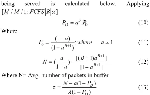
Case-II: Now, considering the case when the proxy node is not used to serve the congested node. In that case, the probability that packet is dropped at node which is not
being served is calculated below. Applying
[M M/ /1:FCFS B]
3 0 .
D
P a P (10)
Where
0 (1 )1 ; 1
(1 B )
a
P where a
a
(11)
1
1 [( 1) ] ( )
1 [1 ]
B B
a B a
N a a
(12)
Where N= Avg. number of packets in buffer
(1 )
(1 )
D D
N a P
P
(13)
Thus, the average number of packets in a buffer at any instant is, 2 1 0 3 2 1 1
[1 ( 1)( ) ( 2)( ) ]
2 2
{[ ]
4 (1 ) 2 [( 1) ] ( 1)
[( ) ] }
1 [1 ]
B B
pt
B B
a a
B B P
N a
a n
a B a n
a a n
(14)
Average waiting time of packets in a buffer is given by,
{
[ (1 )]
P pt D N P n
(1 ) ( 1)}
(1 )
D D
N a P n
P n
(15)
IV.SIMULATIONS &RESULTS
Average number no packets in a buffer and average waiting time of packets in a buffer for the proposed modified ring network, employing different values of B vs packet arrival rate has been investigated with MATLAB. In fig.3 (a) and fig. 3(b) the comparative performance analysis of optical burst switching ring network with and without using proxy node for B=10 and 20 have been shown respectively. For a fixed value of B the nature of the curves of both network are qualitative similar but the modified ring network (with proxy node) can accommodate larger no of packets in its buffer for a particular packet arrival rate. As a result the packet dropping probability decreases in the case of modified ring network and correspondingly throughput of the network increases. In fig. 4(a) and 4(b) the average waiting time in buffer for both types of networks has been depicted. The graph shows that the average waiting time increases for the network with proxy node. The result is obvious because if the proxy node connected between the source and the destination node then the packet has to travel a longer distance so the waiting time will also increase. This result is quite interesting in network application because without adding any additional hardware the incoming packets could be retained in the buffer for longer time thus the packet blocking probability or packet loss probability will be decreased significantly.
buffer becomes important factor for high packet arrival rate or high speed network. But the fig 5(b) infers different results and this figure concludes that waiting time will vary with different n value even if the value of B is fixed. Though the qualitative nature for all values of n is same but the quantitative values are different
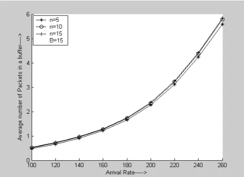
Fig.6(a), (b) and (c) reveal the behavior of the network for different values of n. For low value of B the effect of number of n on network performance is significantly high but as the value of B is increasing the effect due to n is becoming less. Finally for B=15 and above the average waiting time becomes almost independent of the number of nodes associated.
Off course all the analysis presented are for the network under the assumption that the channel and the hardware processing elements do not corrupt the data packets to yield an acceptable grade of service. These observations can be used to employ dynamic load balancing property of the proposed node architecture to obtain a satisfactory reduction in blocking probability at high traffic flow. Thus present analysis is useful for the node designer to optimize the available channels for the minimum blocking probability by utilizing proxy node effectively.
Fig.3 (a):Avg. no of packets in a buffer vs Arrival rate for B=10
Fig.3 (a):Avg. no of packets in a buffer vs Arrival rate for B=20
Fig.4 (a):Avg. waiting time of a packet in a buffer vs Arrival rate for B=10
Fig.4 (b):Avg. waiting time of a packet in a buffer vs Arrival rate for B=20
Fig.5 (b):Avg. waiting time of a packet in a buffer vs Arrival rate for different values of n
Fig 6(a):Avg. no of packets in a buffer vs Arrival rate for different n and B=10
Fig 6(b):Avg. no of packets in a buffer vs Arrival rate for different n and B=15
Fig 6(c):Avg. no of packets in a buffer vs Arrival rate for different n and B=20
V. CONCLUSIONS
This paper addresses the problem of network congestion in an optical burst switching ring network when the packet arrival rate is more than that the service rate of the node. It illustrates the concept involving the design and implementation of a modified ring topology with provisions to adapt dynamically to varying traffic demands. The mathematical modeling involves the calculation of average waiting time as well as the average number of packets in a buffer. The approach adopted here is quite simple and involves basic queueing theory but still provides a well acceptable performance.
REFERENCES
[1] R. Ramaswami and K.N. Sivarajan. “Optical Networks.A Practical Perspective”,2nd Ed. Morgan Kaufmann Publishers, Inc., San Francisco, 2002.
[2] Y.Chen, C.Qiao, and X.Yu, “ Optical Burst Switching : A New Area in Optical Networking Research,” IEEE Network, vol. 18, 2004, pp.16-23.
[3] C. Qiao and M. Yoo, “Optical burst switching (OBS) - a new paradigm for an optical Internet”., J. High Speed Networks, vol. 8, pp. 69-84. Jan.1999.
[4] J. Turner, .”Terabit burst switching”., J. High Speed Networks, vol. 8, pp. 3. 16, 1999.
[5] J.Li and C.Qiao, “ Recent Progress in Scheduling Algorithms in Optical Burst-Switched Netwroks,” OSA Journal of Optical Networking, Vol.3, 2004, pp. 229-241.
[6] J.P.Jueand V.M.Vokkarane, “Optical Burst Switched Networks”, Springer, 2005.
[7] Vokkarane V., Jue J.P., and Sitaraman S. “Burst segmentation: An approach for reducing packet loss in optical burst switched networks,” In Proceeding of IEEE ICC, volume 5, pages 2673-2677, 2002.
[8] Yu X, Chen Y, Qiao C. “Study of traffic statistics of assembled burst traffic in optical burst-switched networks”. Proc OptiComm, p 149– 159, July–Aug 2002.