International Journal of Engineering
J o u r n a l H o m e p a g e : w w w . i j e . i rA Capacitive Fed Microstrip Patch Antenna with Air Gap for Wideband Applications
M. M. Fakharian*, P. Rezaei, A. Azadi, M. R. Dadras
Department of Electrical and Computer Engineering, Semnan University, Semnan, Iran
P A P E R I N F O
Paper history: Received 03 July 2013
Received in revised form 28 September 2013 Accepted 07 November 2013
Keywords:
Microstrip Patch Antenna Capacitive Fed Suspended Wideband
A B S T R A C T
In this paper, a microstrip antenna on a suspended substrate with capacitive feed is presented. capacitive feed is created by a slot within the rectangular patch around the feed point. The proposed antenna exhibits a much higher impedance bandwidth of about 47% (S11 < −10 dB). Effects of key design parameters such as the air gap between the substrate and the ground plane, the gap width between radiator patch and feed point, and the location of the feed point on the input characteristics of the antenna have been investigated and discussed. A prototype of the antenna is also fabricated and tested to verify the design. Measured characteristics of the antenna are in good agreement with the simulated results.
doi:10.5829/idosi.ije.2014.27.05b.06
1. INTRODUCTION1
Microstrip patch antennas are widely preferred for wireless communication systems that typically require antennas with small size, light weight, low profile, and low cost [1]. However, basic geometries of these antennas suffer from a small bandwidth, which is of the order of a few percent of the operational frequency. Therefore, it has been investigated by several researchers that the bandwidth of Microstrip Antenna (MSA) can be significantly improved. These alterations include, increasing the height (or thickness) of the substrate, cutting slots in the basic shapes, changing the shape of the geometry, using multi layer techniques, metamaterials, or adding a shorting pin and so on [2-10]. Typically, aperture and electromagnetic coupling methods of feeding are also used in stacked configurations to avoid the spurious radiations from the feed network while improving the impedance bandwidth [11, 12]. Many of these have relatively complex assembly, which in some cases is contrary to the fundamental attraction of MSAs.
The coaxial probe is a simple feeding method for electrically thick substrates. In these substrates, the inductance of the probe may create the impedance
*Corresponding Author Email: m_fakharian@sun.semnan.ac.ir (M. M. Fakharian)
mismatch which can be compensated by wideband impedance-matching networks, edge-coupled patches, stacked elements, shaped probes, and finally capacitive coupling and cutting slots on the patch [13, 14]. Several innovative feeding techniques have also been suggested to improve the bandwidth which included modification to a meandered [15] and L-probe [16] feeds.
Alternatively, recently capacitive fed suspended MSA configurations with improvement of bandwidth are found in the literatures [17-22]. A rectangular MSA with a small coplanar capacitive feed strip is reported in [17]. In this antenna the radiator patch and a smaller feed patch are located on the same plane and the antenna substrate is located above the ground plane with an air gap separation. A circularly polarized (CP) MSA on a suspended substrate with a capacitive feed and a slot within the rectangular patch is proposed [19]. Moreover, an annular ring and narrow rectangular slots around the feed point in the radiating patch are presented in litrature [23, 24], respectively. By choosing suitable dimensions of the ring or rectangular slot, the large probe reactance can be compensated. A good impedance matching over a wide bandwidth can be also obtained.
In this paper, we use a configuration which appears like that in litrature [23]. The patch is matched using a rectangular gap around the feed point. After introducing the basic configuration of the antenna in Section II, we
represent in Section III a detailed parametric study on the various design aspects of such an antenna for a rectangular patch configuration. The effects of truncating patch corners to achieve CP operation have been also presented there. Experimental validation of a prototype is presented in Section IV.
2. ANTENNA DESIGN AND CONFIGURATION
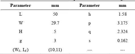
The basic geometry of proposed antenna is shown in Figure 1. The antenna substrate is placed above the ground plane with a distance of H. As will be shown in Section III, this distance has an important role in maximizing the obtained bandwidth. The antenna structure is fabricated on an FR4 substrate with dielectric constant of 4.4, loss tangent of 0.02 and thickness of h=1.58mm. The patch dimensions are designed for central frequency (3.5GHz) with regards to necessary corrections for the suspended dielectric [1]. A typical set of dimensions for the design are listed in Table 1.
(a) Cross-sectional view
(b) Top view
Figure 1. Geometry of the proposed patch antenna with
capacitive fed.
TABLE 1. Dimension of the Optimized Antenna Design.
Parameter mm Parameter mm
L 50 h 1.58
W 29.7 p 3.175
H 5 q 2.324
g 3 s 0.162
(Wf , Lf ) (10,11) --- ---
The configuration is based on the method of suspended capacitive fed MSA. The method described here is to etch a rectangular gap on the patch concentric with the probe feed. This introduces a series capacitance at the patch input and results in a much lower input resistance and therefore a usable input stripline impedance of 40 to 120 ohms, depending on the magnitude of the capacitance [19]. The idea behind the capacitive feed is quite simple. At resonance, the probe inductance and capacitance inherent to the antenna equivalent circuit cancel each other out, leaving real impedance [24]. The probe admittance is determined by enforcing a continuity of power flow at the aperture. The equivalent circuit elements for the probe that included in the patch impedance evaluation are:
probe of diameter d
kd h
LP
=
ú û ù ê
ë é
+ ÷ ø ö ç è æ
-= g
p m
4 ln 2
0
(1)
with ω=2πf, μ0=4π×10-7 H/m and γ=0.5772 (Euler’s constant). The capacitor is chosen such that its reactance is sufficient to cancel the residual reactance of the probe inductance. The required capacitance is:
P r m
L
C 21
w
= (2)
where, wr is the resonant frequency and LP is the probe inductance. Thus, the extra capacitance brings the impedance back to resonance, and the wider bandwidth of the ticker substrate can be realized. Reference [24] gives approximate expression for the etched capacitors. The capacitors is:
(
)(
q p)
p q
Cm ÷÷ r + +
ø ö çç è æ
= p ' e0 e 1 ' (3)
q' = q – 2s, with s being the gap width; p and q are the capacitor length and width, respectively.
3. PARAMETRIC STUDY ON ANTENNA
PERFORMANCE
In the presented study, we used a very small rectangular gap around the feed point and retained the basic configuration of antenna with a substrate above the ground plane and an air gap between them. We further show that by properly choosing the size of rectangular gap and the height of the air gap, the impedance bandwidth can be significantly improved.
thickness of slot around the feed point (s), and the location of the feed point (Wf ,Lf). In the following subsections, we examine the effects of these parameters on the antenna performance. All simulations are carried out using HFSS, which is based on the Finite Element Method (FEM).
3. 1. Effect of Air Gap (H) It is widely understood that as the effective substrate height increases or permittivity decreases, MSAs result in wider bandwidth. In the presented configuration, when two resonant frequencies are close enough these may merge to form single operational band with return loss below −10dB. This may happen only for a certain range of values of
“H”. The effect of air gap on the return loss characteristics of the antenna is shown in Figure 2 and the bandwidth along with corresponding dimensions of key design parameters for each case are summarized in Table 2.
One of the reasons for the antenna impedance to be dependent on the air gap is the change in inductance of the probe pin [25]. If we increase the air gap and keeping the dimensions of other parameters as in Table 1, the resulting antenna will have two separate, narrow bands of operation. The shift in the resonant frequency is due to the fact that when air gap increases, the effective dielectric constant changes; and this leads to change in the effective dimensions of the patch. Although the impedance bandwidth obtained for H=6mm (48.10%) and H=6.5mm (49.43%) are slightly higher than that for H=5.5mm (46.93%), the latter is selected because it ensures a better minimum S11 from
-10dB.
3.2. Effects of the Gap Width Around the Feed Point (s) The bandwidth of antenna can be restored to the maximum value by optimization the gap width (s). As shown in Figure 3 and Table 3, with the decrease in gap width, the return loss curve splits into two separate narrow bands, if all other parameters are kept constant. In addition, antenna input resistance increases and the input reactance decreases with a decrease in the width of gap. For s≤0.162mm, frequency band splits into two parts. For s≥0.162mm, even though we get approximately the same impedance bandwidth with a slight reduction, increasing the dimensions of the gap width produces asymmetry in the radiation patterns and results in a reduction in useful bandwidth.
The coupling capacitance due to the separation between the radiator patch and feed point (s) plays an important role in selecting the width of the gap. The value of gap capacitance due to s can be calculated using Equation (3) given in section II. Note that the inductive reactance offered by the probe [25] must be taken into account in the proposed configuration. However, from the observations we made in our
detailed parametric study, we can use the minimum values of “s” as 0.162mm.
Figure 2. Return loss characteristics for different values of air
gap (H). The other design parameters are kept constant in accordance with Table 1.
Figure 3. Effects of gap width (s) on impedance bandwidth
TABLE 2. Design Parameters for Various Curves Presented
in Figure 2 Showing the Effects of the Air Gap on the Antenna Bandwidth.
Air gap H, mm Impedance bandwidth %, (GHz)
5 44.57% (2.79-4.39 GHz)
5.5 46.93% (2.74-4.42 GHz)
6 48.10% (2.70-4.41 GHz)
6.5 49.43% (2.65-4.39 GHz)
TABLE 3. Effects of the Variation in the Gap Width (S) on
the Antenna Bandwidth, Other Design Parameters Are as Listed in Table 1.
Gap width s, mm Impedance bandwidth %, (GHz)
0.062 (2.77-3.57 / 3.73-4.39 GHz)
0.162 46.93% (2.74-4.42 GHz)
0.262 45.90% (2.77-4.42 GHz)
0.362 44.78% (2.79-4.40 GHz)
2.5 3 3.5 4 4.5
-35 -30 -25 -20 -15 -10 -5 0
R
et
ur
n
l
o
ss
(
dB)
Frequency (GHz)
5.0 mm 5.5 mm 6.0 mm 6.5 mm
2.5 3 3.5 4 4.5
-35 -30 -25 -20 -15 -10 -5 0
R
et
u
rn
l
oss
(
dB)
Frequency (GHz)
The effect of changing the length of the gap around the feed point (p,q) has also investigated. It is found that the bandwidth of antenna can be restored to the maximum value by decreasing length of the gap. The coupling capacitance due to the separation between the radiator patch and feed point play an important role in selecting the dimensions of the length of the gap. So, due to physical limitations and practical considerations of fabrication, the minimum values of “p” and “q” are used as 3.175mm and 2.324mm, respectively.
3. 3. Effects of Feed Location (Wf, Lf) The location
of the feed point plays a critical role in obtaining the wide bandwidth for the proposed antenna. The feed location (Wf,Lf) are assigned different values. Its effects
on the impedance bandwidth of antenna are shown in Figure 4 and Table 4. For Wf≤ 8mm and Lf≥ 12.5mm,
the return loss characteristics curve splits into two separate or narrow bands of operation. When Lf=10mm
and Wf=11mm, the impedance bandwidth is wider and
reaches to 46.93% and the minimum S11 is −24.28dB.
Figure 4. Effects of feed location (Wf , Lf) on impedance
bandwidth
Figure 5. Simulated axial ratio in the broadside direction for
the antenna studied in Figure 1
TABLE 4. Impedance Bandwidth for the Antenna for Varying
Feed Location (Wf , Lf).
Feed location (Wf, Lf), mm
Impedance bandwidth %, (GHz)
Minimum S11, dB
(6,11) 14.70% (3.72-4.31 GHz) -15.31
(8,11) 42.78% (2.83-4.37 GHz) -26.47
(10,11) 46.93% (2.74-4.42 GHz) -24.28
(11.2,11) 48.74% (2.70-4.44 GHz) -19.07
(10,12.5) 44.41% (2.75-4.32 GHz) -32.91
(10,15.5) 30.93% (2.76-3.77 GHz) -26.74
(10,17) 29.37% (2.76-3.71 GHz) -23.41
3. 4. Simulation Studies for Circular Polarization Operation In the proposed antenna by a corner-truncated microstrip patch, a single-feed, CP MSA can easily be obtained [27]. The dimension of truncated corners is shown in Table 1. Figure 5 presents the simulated axial ratio of designed antenna at 0° in elevation angle. The simulated 3-dB AR bandwidth at 4GHz is 4.1% (3.87–4.03GHz). This axial ratio bandwidth covers the impedance bandwidth of the antenna.
4. EXPERIMENTAL RESULTS
The antenna shown in Figure 1 with dimensions described in Table 1 has been fabricated on an FR-4 substrate with dielectric constant of 4.4, loss tangent of 0.02, and thickness of 1.58mm. This substrate is assembled above an aluminum ground plane of dimensions of 62.5×80mm2. The antenna is exited by
connecting a coaxial probe to the rectangular patch by a long pin SMA connector. Energy from this feed patch is electromagnetically coupled to the radiating patch. Photographs of the fabricated prototype are shown in Figure 6(a). This prototype antenna is tested for S11
using Vector Network Analyzer Agilent, as shown in Figure 6(b). Radiation patterns are measured in an in-house microwave anechoic chamber by a swept frequency measurement.
The return loss characteristics obtained from simulation and measurement are shown in Figure 6(c). The measured S11 is better than −10dB (VSWR<2) for
frequencies in the range of 2.79–4.47GHz. This corresponds to a percentage bandwidth close to 46.28%. It can be noticed from Figure 6 that measured data are in good agreement (small difference may be attributed due to fabrication inaccuracies) with the simulated result.
The measured radiation patterns of the proposed antenna are plotted at 3 and 4GHz frequencies (minimum return loss frequency points) within band and
2.5 3 3.5 4 4.5 5
-35 -30 -25 -20 -15 -10 -5 0
R
et
ur
n
lo
ss
(
dB)
Frequency (GHz)
(6,11mm) (8,11mm) (10,11mm) (11.2,11mm) (10,12.5mm) (10,15.5mm) (10,17mm)
3.7 3.8 3.9 4 4.1
0 1 2 3 4 5 6 7
Ax
ia
l r
a
tio
(
d
B)
are shown in Figure 7. Large cross-polarization is observed for both operating frequencies, which is a common characteristic of this kind of probe-fed MSA with a thick air substrate. It should be noted that this characteristic can be an advantage for indoor wireless communication applications [2]. The antenna gain is also measured, and the results are presented in Figure 8. The peak antenna gain is about 9.5dB, and the measured gain of antenna is greater than 4dB nearly throughout the band.
(a)
(b)
(c)
Figure 6. Experimental validation of the input characteristics
of the antenna, (a) top view of the fabricated antenna, (b) the antenna connected to the Network Analyzer, and (c) simulated and measured comparison
(a)
(b)
Figure 7. Measured co- and cross-polarization patterns of the
proposed patch antenna at (a) 3GHz, and (b) 4GHz frequencies
Figure 8. Measured gain for the antenna in Figure 6.
5. CONCLUSION
A microstrip patch antenna with a capacitive feed is proposedhere. After presenting thebasic configuration involving a rectangular patch and a rectangular gap around the feed point, the effects of all key design parameters are studied for optimum design. Return loss bandwidth (below −10dB) of nearly 47% has been obtained for a wide range of frequencies. When the gap width dimension around the feed point is increased, the antenna bandwidth appears to be lessened. On the other hand, the gap width dimensions cannot be reduced
2.5 3 3.5 4 4.5
-35 -30 -25 -20 -15 -10 -5 0
R
et
ur
n
lo
ss
(
dB)
Frequency (GHz) Simulated Measured
-40 -30 -20 -10
30
210 60
240
90 270
120
300
150
330
180 0
E-Co
E-Cross
H-Co
H-Cross
-20 -30 -40 -10
30
210 60
240
90 270
120
300
150
330
180 0
E-Co E-Cross H-Co H-Cross
2.5 3 3.5 4 4.5
-5 0 5 10
G
ai
n
(
d
B)
below limits to avoid problems in soldering the probe pin. The antenna can be designed at any frequency to get the similar performance by selecting proper air gap value and corresponding dimensions of the patch. Based on the results presented here, the proposed feed scheme is versatile and can be employed for designing simple to fabricate wideband microstrip patch antennas.
6. ACKNOWLEDGMENT
The authors would like to thanks to Mr. Solat, Mr. Mirabdollahi and Mr. Akhlaghpasandi for measurements of the antenna. We also would like to express our thanks to Mr. Valizade for his valuable remarks. This work has been supported financially by the Office of Brilliant Talents at the Semnan University.
7. REFERENCES
1. Balanis, C. A., "Antenna Theory, Hoboken", New Jersey: John Wiley & Sons, Inc, Vol. 8, No., (2005), 21-31.
2. Kinlu, W., Compact and broadband microstrip antennas., Hoboken: John Wiley & Sons. (2002)
3. Fakharian, M. M. and Rezaei, P., "Numerical Analysis of Mushroom-Like and Uniplanar EBG Structures Utilizing Spin Sprayed Ni (–Zn)–Co Ferrite Films for Planar Antenna", European Journal of Scientific Research, Vol. 73, No. 1, (2012), 41-51.
4. Garg, E. R., "Investigation on microstrip patch fractal antenna", International Journal of Engineering,Transactions C: Aspects, Vol. 25, No. 1, (2012), 39-44.
5. Kumar, G. and Ray, K., "Broadband microstrip antennas, Artech House, (2003).
6. Valizade, A., Ghobadi, C., Nourinia, J. and Ojaroudi, M., "A novel design of reconfigurable slot antenna with switchable band notch and multiresonance functions for UWB applications", Antennas and Wireless Propagation Letters, IEEE, Vol. 11, No., (2012), 1166-1169.
7. Rahanandeh, M., Noor Amin, A. S., Hosseinzadeh, M., Rezai, P. and Rostami, M. S., "A compact elliptical slot antenna for covering bluetooth/WiMAX/WLAN/ITU", Antennas and Wireless Propagation Letters, IEEE, Vol. 11, (2012), 857-860. 8. Fakharian, M. M., "Multiple fork-like EBG structure and its
analysis as artificial magnetic conductor", in Antennas and Propagation (EUCAP), 6th European Conference on, IEEE., (2012), 1-4.
9. Arghand Lafmajani, I. and Rezaei, P., "Miniaturized rectangular patch antenna loaded with spiral/wires metamaterial", European Journal of Scientific Research, Vol. 65, No. 1, (2011), 121-130.
10. Razi, Z. M., Rezaei, P. and Zaman, M. E., "Improving the bandwidth of high gain Fabry-Perot antenna using EBG substrate", Vol. 7, No. 2, (2013), 78-81
11. Fakharian, M. M., Rezaei, P. and Shahzadi, A., "Analysis of Far-Field Radiation from Apertures Using Monte Carlo Integration Technique", Majlesi Journal of Electrical Engineering, Vol. 7, No. 3, (2013), 25-34.
12. Fakharian, M. and Rezaei, P., "Parametric study of UC-PBG structure in terms of simultaneous AMC and EBG properties and its applications in proximity-coupled fractal patch antenna", International Journal of Engineering-Transactions A: Basics, Vol. 25, No. 4, (2012), 347.
13. Kasabegoudar, V. G., Upadhyay, D. S. and Vinoy, K., "Design studies of ultra-wideband microstrip antennas with a small capacitive feed", International Journal of Antennas and Propagation, Vol. 2007, (2007).
14. Vandenbosch, G. A. and Van de Capelle, A. R., "Study of the capacitively fed microstrip antenna element", Antennas and Propagation, IEEE Transactions on, Vol. 42, No. 12, (1994), 1648-1652.
15. Lai, H. W. and Luk, K. M., "Wideband stacked patch antenna fed by meandering probe", Electronics Letters, Vol. 41, No. 6, (2005), 297-298.
16. Islam, M. T., Shakib, M. and Misran, N., "Design analysis of high gain wideband L-probe fed microstrip patch antenna", Progress In Electromagnetics Research, Vol. 95, (2009), 397-407.
17. Kasabegoudar, V. G. and Vinoy, K. J., "Broadband suspended microstrip antenna for circular polarization", Progress In Electromagnetics Research-Pier, Vol. 90, (2009), 353-368. 18. Mayhew-Ridgers, G., Odendaal, J. W. and Joubert, J.,
"Single-layer capacitive feed for wideband probe-fed microstrip antenna elements", Antennas and Propagation, IEEE Transactions on, Vol. 51, No. 6, (2003), 1405-1407.
19. Alexander, M., "Capacitive matching of microstrip patch antennas", in Microwaves, Antennas and Propagation, IEE Proceedings H, IET. Vol. 136, (1989), 172-174.
20. Kasabegoudar, V. G. and Vinoy, K., "Coplanar capacitively coupled probe fed microstrip antennas for wideband applications", Antennas and Propagation, IEEE Transactions on, Vol. 58, No. 10, (2010), 3131-3138.
21. Solanki, M. R., Kiran, K. U. and Vinoy, K., "Broadband Design of a Triangular Microstrip Antenna with a Small Capacitive Feed", Journal of Microwaves, Optoelectronics and Electromagnetic Applications, Vol. 7, No. 1, (2008), 44-53. 22. Kasabegoudar, V. G. and Vinoy, K., "A wideband microstrip
antenna with symmetric radiation patterns", Microwave and Optical Technology Letters, Vol. 50, No. 8, (2008), 1991-1995. 23. Oraizi, H. and Hedayati, S., "Combined fractal geometries for the design of wide band microstrip antennas with circular polarization", in Microwave Symposium (MMS), 2010 Mediterranean, IEEE. Vol., No. Issue, (2010), 122-125. 24. Sainati, R. A., "CAD of microstrip antennas for wireless
applications, Artech House, Inc., (1996).
A Capacitive Fed Microstrip Patch Antenna with Air Gap for
Wideband Applications
RESEARCH NOTE
M. M. Fakharian, P. Rezaei, A. Azadi, M. R. Dadras
Department of Electrical and Computer Engineering, Semnan University, Semnan, Iran
P A P E R I N F O
Paper history: Received 03 July 2013
Received in revised form 28 September 2013 Accepted 07 November 2013
Keywords:
Microstrip Patch Antenna Capacitive Fed Suspended Wideband
هﺪﯿﮑﭼ
ﻪﯾﻻﺮﯾزيورﺮﺑﺐﯾﺮﺘﺳاوﺮﮑﯾﺎﻣﻦﺘﻧآﮏﯾﻪﻟﺎﻘﻣﻦﯾارد ﺖﺳاهﺪﺷﻪﺋاراﯽﻧزﺎﺧﻪﯾﺬﻐﺗﺎﺑﻖﻠﻌﻣيا
.
ﮏﯾﻪﻄﺳاﻮﺑﯽﻧزﺎﺧﻪﯾﺬﻐﺗ
ﺖﺳاهﺪﺷدﺎﺠﯾاﻪﯾﺬﻐﺗﻪﻄﻘﻧفاﺮﻃاﯽﻠﯿﻄﺘﺴﻣﭻﭘﻞﺧادفﺎﮑﺷ
.
يﺎﻨﻬﭘﮏﯾهﺪﺷدﺎﻬﻨﺸﯿﭘﻦﺘﻧآ دوﺪﺣردﯽﺴﻧاﺪﭙﻣاﺪﻧﺎﺑ
47 %
)
S11<-10dB (
ﯽﻣنﺎﺸﻧ ﺪﻫد
.
ﺪﻨﻧﺎﻣﯽﺣاﺮﻃﻢﻬﻣيﺎﻫﺮﺘﻣارﺎﭘتاﺮﺛا
:
ﺖﻣﺎﺨﺿ،ﻦﯿﻣزﻪﺤﻔﺻوﻪﯾﻻﺮﯾزﻦﯿﺑﯽﯾاﻮﻫ ﻪﻠﺻﺎﻓ
ﺖﺳاهﺪﺷﺚﺤﺑوﯽﺳرﺮﺑﻦﺘﻧآيدوروﻪﺼﺨﺸﻣﺮﺑﻪﯾﺬﻐﺗﻪﻄﻘﻧﺖﯿﻌﻗﻮﻣو،ﻪﯾﺬﻐﺗﻪﻄﻘﻧوهﺪﻨﻨﮐﻊﺸﻌﺸﺗﭻﭘﻦﯿﺑفﺎﮑﺷ
.
ﺖﺳاهﺪﺷﺖﺴﺗوﻪﺘﺧﺎﺳﻦﺘﻧآزاﻪﯿﻟواﻪﻧﻮﻤﻧﮏﯾﻦﯿﻨﭽﻤﻫ
.
ﻪﺼﺨﺸﻣ
يﺎﻫ هاﺪﻧا
ﻪﯿﺒﺷﺞﯾﺎﺘﻧﺎﺑﻦﺘﻧآزاهﺪﺷيﺮﯿﮔ
هﺪﺷيزﺎﺳ
ﺪﻧرادﯽﺑﻮﺧﻖﺑﺎﻄﺗ
.
doi:10.5829/idosi.ije.2014.27.05b.06