A b s t r a c t. This paper describes the development of an embedded real-time system devoted to microclimate control in a complex greenhouse. The control system is capable of managing multiple, independent poly-tunnel units (PTUs). Both the internal temperature and humidity of PTUs as well as the external temperature, rainfall and wind conditions are monitored and regulate decisions of the control system. The control system is di-rected by parameters entered at configuration time through a user-friendly graphical interface. The realization depends on the use of Java technologies and on a specific methodology suited to the development of real-time systems. The approach is based on hierarchical state machines extended with timing constraints, and a supporting toolbox which enables graphical modelling, automatic code generation, simulation and real-time execution of a system. The paper discusses design and implementation aspects of the control system and reports information collected from real operation.
K e y w o r d s: greenhouse climate control, embedded real-time systems, statecharts, integrated development, Java
INTRODUCTION
Greenhouse climate control (Critten and Bailey, 2002) is a well-known challenging problem. It affects both the quality of produced horticultures and the economic expectations of the growers. Several models have been proposed in the literature,eg(Albrightet al., 2001; Cunha, 2003; Caponettoet al., 2000; Mirandaet al., 2006) which can predict the values of environment variables (air temperature, relative humidity, CO2, light radiation,etc.) with the help of AI based techniques (genetic algorithms, artificial neural networks, fuzzy logic and so forth). These models are intrinsically difficult due to the complex
interrelations which exist between greenhouse internal and external environment variables. For instance, model time-variant parameters are often required which make value prediction imprecise and with a limited time horizon validity. In addition, models can be highly demanding from the computational point of view, which makes them not always adequate for use in real-time operation.
In the work described in this paper a purely software-based approach is experimented. The approach is event-driven, time-driven and domain expert-driven. The beha-viour of the control system mainly consists in the periodic reading of data from sensors and in the elaboration of corresponding response actions to be executed on actuators. Responses are sensitive to the configuration data entered by the greenhouse domain expert at system start-up time.
The development technology is centred on Java and in particular on the Hierarchical Communicating Real-Time State Machines modelling language and the supporting toolbox VIOLIN (Furfaro et al., 2006). VIOLIN permits visual modelling, simulation with RTL-like assertions, and Java code generation of an H-CRSM system. The generated code of a final system is automatically weaved with a custom runtime executive which supports cooperative concurrency and favours time predictability.
The achieved embedded real-time system is actually in charge of climate control in a complex greenhouse con-sisting of multiple and independent poly-tunnel units (PTUs), used for possibly different horticultures at a given time. The system is in real use and has significantly improved the management of the before manually operated physical system. Two basic goals were pursued: 1) pro-tecting the greenhouse structure from damage by reacting in
© 2007 Institute of Agrophysics, Polish Academy of Sciences
*Corresponding author’s e-mail: [email protected]
due time to external wind events and rainfalls, which obviously can also occur in combination; 2) maintaining the air temperature and relative humidity in the various PTUs within required ranges of values through PTU windows opening/closing and possibly by activating the local heater or the cooling sub-system.
The paper describes design and implementation aspects of the greenhouse climate control system together with its supporting H-CRSM methodology. The real operation of the system is then demonstrated through execution scenarios based on sampled history of logged events and reactions.
GREENHOUSE SYSTEM
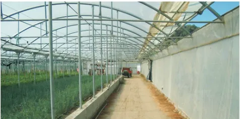
The greenhouse physical system, located in the southern of Italy, occupies a surface of 12000 m2, with 28 tunnels partitioned into 6 poly-tunnel units (PTUs). Figure 1 shows a typical PTU.
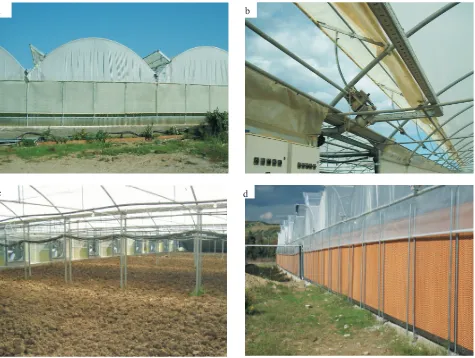
The greenhouse produces both flowers eg chrysan-themum and horticultures eg string bean. Tunnels are covered by polyethylene sheets. PTUs are units for data sampling and control. They are provided with sensors for capturing the internal air temperature and relative humidity. Tunnels in a PTU have roof windows (Fig. 2a) extending over the whole length of the tunnel, which can be opened/ closed through asynchronous three phase motors (Fig. 2b). Each PTU is also equipped with front/rear and lateral windows but at current time only the roof windows are under the automatic control of the software system. Depending on window placement, a tunnel can have one (near the highest position of the cover) or two (in low and opposite positions of the cover) windows.
The greenhouse is powered with a total wattage of 25KW. Particular attention was devoted to provisions capable of reducing the electrical power requirements. For instance, some PTUs can have their roof windows partitio-ned into two groups of alternating windows. When the need arises, windows of the two groups are then operated in an
interleaved way. A similar provision is exploited for actuating the electrical fans of the PTU cooling system (Fig. 2c, d). In this case, up to three groups of fans can be established, with the first group comprising fan motors which are actuated through an inverter and the remaining group motors which are on/off actuated. Finally, a PTU can have a heater (boiler) which can generate warm air during winter cold conditions.
The whole greenhouse is equipped with a meteoro-logical box with sensors for reading the external air tempera-ture, velocity and direction of wind and the presence/ absence of a rain/snow fall. Such data are shared and can influence the operation of all the PTUs.
DESIGN OF THE CLIMATE CONTROL SYSTEM
The following outlines the design and implementation of the proposed greenhouse climate control system -CCS-, along with its supporting methodology. The software system runs on a single Win2k platform.
Supporting methodology
CCS development is based on the H-CRSM modelling language (Furfaroet al., 2006) which is an extension with statecharts (Harel, 1987) of the Communicating Real-Time State Machines (Shaw, 1992; Raju and Shaw, 1994; Fortino and Nigro, 2000). H-CRSM represents a software archi-tecture (Shaw and Garlan, 1996). Machines are the basic building blocks. They hide a behaviour modelled as a distil-led statechart where only the or-decomposition of states is allowed. Machines follow a distributed model of concur-rency: they share no data and concurrently execute except when they need to interact. The communication model is patterned à la CSP ieit is based on synchronous (rendez vous) unidirectional 1-to-1 channels with typed messages, linking matching input/output ports. State transitions in a ma-chine are annotated by a guarded command with a timing constraintiea time interval [a,b], 0£a£b, b can be¥. When a=b, the time interval is abbreviated as [a]. Basic commands are:input(?),output(!),timer?, or aninternal command. The timing constraint is relative to the instant in time when the current state was entered and serves to express the temporal readiness of an enabledieguard is true command. Internal commands have a hidden and implicit time constraint of [0,¥], whereas the explicit time interval is instead a duration interval [d1,d2] meaning that the
implicitly saves in the variable v the system real time (returned by the functionrt()) when the timer expires. All of this can be exploited, for instance, to achieve a periodic behaviour.
Time constraints determine, among the enabled commands in a given machine, which command is eligible for execution. Conflicts among transitions outgoing current state of a machine are resolved according to theearliest time firststrategy which forces firing the (ora) command having earliest occurrence time. The other commands are then discarded. In the case of multiple candidate events, one is chosen non-deterministically.
Full life-cycle development of H-CRSM systems is enabled by theVIOLINtoolbox (Furfaroet al., 2006) which permits graphical modelling, simulation with RTL-like assertions (Shaw, 1997; Fortino and Nigro, 2000) for functional/temporal property checking, and Java code generation of a system. The code generator weaves the final system implementation with a library of Java classes (framework) handling statechart hierarchies and dynamic
evolution, interface classes for accessing the native driver code of sensors/actuators (Fig. 3) and a custom real-time executive which ensures cooperative concurrency instead of Fig. 2.Particular of: a – roof windows, b – a window motor, c – a PTU’s cooling fans, and d – opposite side of PTU’s cooling panels.
d c
over-killing concurrency and pre-emption. The runtime system makes it possible to statically allocate the memory of all the objects (states, transitions, channels, data messages and so forth) needed by an implemented system. The pro-vision avoids interventions of the Java garbage collector.
CCS Architecture
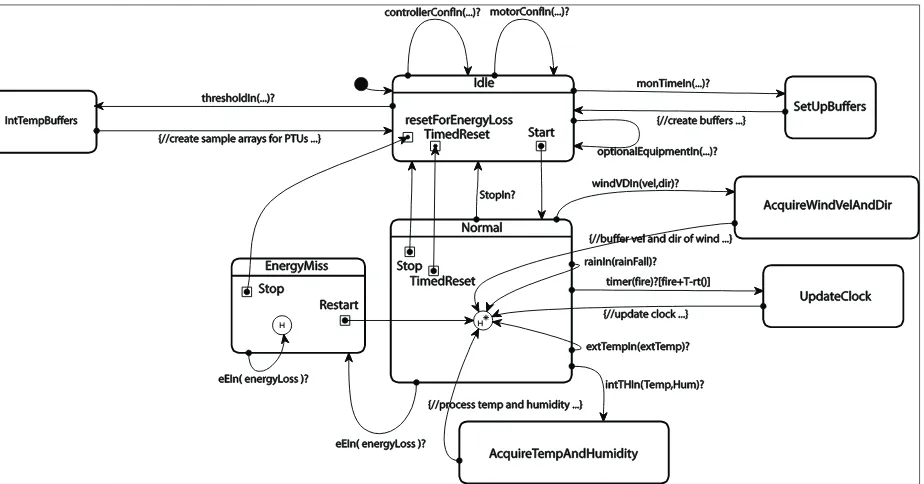
Figure 4 depicts the H-CRSM architecture of CCS composed of a collection of interconnected statechart machines. The architecture is closed: particular machineseg sensor and motor machines explicitly model the external controlled environment (greenhouse). For instance, WindVelDirSensor machine reads wind velocity and direction; RainSensor communicates to the Controller the presence/absence of a rainfall; IntTempHumSensor machi-ne samples the internal air temperature and relative humidity on a per PTU basis, and so forth. The Configurer takes data entered by the greenhouse manager at the CCS GUI and uses this information to initialize the various machines. The Con-figurer is also capable of starting/ stopping the Controller. Configuration data belong to the following categories:
a) physical boards informationiebase address, port bit assignments for commanding a reading from a sensor or an actuation to a motor;
b)motor timesegthe maximum time (»70 s) required by a window motor for a full open/close operation starting respectively from a closed/opened state. Other attributes re-late to thescanning times (motor scanners in Fig. 4) when actuating a group of motors of a PTU through interleaving;
c) control informationiethe data upon which the control system bases its operation. The first kind of control information concerns the indication of the active PTUsie those effectively included for monitoring and control. The second type of control information relates to the specifi-cation of the optional equipments of PTUs. For example, an enabled and active PTU can have or not the heater or the cooling system installed and/or enabled. The third kind of control information refers to thresholds iethe admissible ranges of values for the various controlled environmental variables,egthe internal temperature/humidity of a PTU, the wind velocity/direction with respect to which a PTU must react, the times at which, for a PTU, the day starts, the evening starts, the night starts, and so forth.
The control strategy of CCS was designed to react, in general, not to instantaneous changes in the environment variables, but to trend of variation. Toward this, values of a controlled variableegwind velocity are buffered in a push-out queue so as to support trend variation reasoning. The size of a buffer depends on the reading period of the variable and on the observation periodiea time parameter entered by GUI which allows to memorize multiple variable samples. In addition, a settlement time can be used to separate consecutive control actions of CCS. Some events, thougheg
rain can require an immediate response. The control strategy is compatible with the temporal dynamics of the greenhouse system and purposely avoids intermittent window actuation, with obvious motor consumption problems eg during circumstances of rapid and irregular wind events.
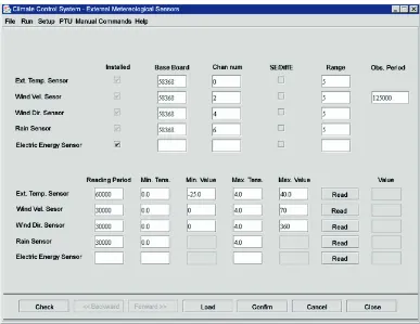
Figure 5 shows a screenshot of CCS GUI for entering sensor parameters for the external meteorological box. As one can see, for each external variable, the reading period and linearization information necessary for translating electrical samples in the corresponding measurement units eg °C for the air temperature can be furnished. At con-figuration time, a functionality check can be performed by asking a read operation to a selected sensor. Set-up para-meters can be verified for correctness and can be saved/ restored to/from a disc file.
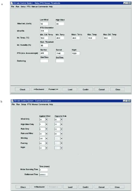
The GUI panel in Fig. 6a permits thresholds for a given PTU to be entered. Both the meaning of low or high wind velocity is specified, as well as the orientation (against north) of the greenhouse, useful to sense wind direction. For the internal temperature, a critical minimum (tcmin), minimum (tmin), mean (tmean), maximum (tmax), critical maximum
(tcmax) set points can be entered. Also the value (hmax) which
specifies a high internal humidity can be specified. Finally, the operator can insert the minutes from midnight after which respectively the day starts, the evening starts or the night starts for the given PTU.
Panel in Fig. 6b allows one to enter, on a PTU basis, the response which CCS should actuate on the occurrence of external events. For example, in the event of a low wind, the PTU windows directly against wind should be opened at 30% of their maximum opening, whereas the PTU windows on the opposite side should be opened at 80%. The same behaviour is specified when the combination low wind/rain occurs. Figure 6b also shows the open percentage of PTU windows which should be adopted by CCS at the various time intervals of the day. The same GUI allows to enter the motor scanning time and the settlement time.
Fig.
4.
H
-CRSM
architecture
of
Control logic
The mission of CCS is to preserve the integrity of the greenhouse system against wind/rain external events, then to maintain the internal temperature of PTUs within the corresponding required interval [tmin..tmax] and the relative humidity below the associated hmax value. Since tempe-rature is assumed to be a more critical factor for growing plants in the greenhouse than humidity, CCS reacts to a high relative humidity but its ultimate goal is to keep the air temperature under control.
From time to time the external wind velocity/direction, rain and temperature conditions are analysed and the corresponding responses identified, namely the opening percentage of PTU windows. The required closing/opening actions, whose exact amount obviously depends on the actual opening percentage of windows, are compared against those prescribed by the greenhouse expert for the current time of day. The minimal request (worst case) is determined also considering the response requirements arising from the internal air temperature control. In order to summarize temperature control, it is useful to observe that two intervals exist for the relative humidity:
normal=[<hmax], exceptional=[>=hmax].
Normal humidity
In the case the humidity is in the normal range, six intervals are considered for the internal air temperature: A=[<tcmin], B=[tcmin..tmin], C=[tmin..tmean], D=[tmean..tmax], E=[tmax..tcmax], F=[>tcmax]. First the CCS classifies the temperature in its belonging interval, then its trend of variation is detected. It is the diminishing/increasing character of the air temperature which dictates the reaction of the CCS. In the case the interval is A or B and the PTU has an installed and enabled heater, the latter is turned on (with PTU windows totally closed). After two consecutive steps in which the internal temperature is found in this too cold condition and also the external temperature is low, an alarm is raised to the human operator in order to check heater functionality and/or the behaviour of temperature sensors. Another alarm is raised in the situation the heater should be turned on and it is disabled at the moment eg for maintenance problems. Similar considerations hold for the cases when the internal air temperature is found belonging to E or F intervals and the PTU has an installed and enabled cooling system (whose operation requires the PTU windows to be kept fully closed, too).
Exceptional humidity
In this case three intervals for the temperature are recognized: low=[<tmin], normal = [tmin..tmax], high=[>tmax]. If the internal temperature is lowegduring winter nights or too cold days, and also the external temperature is low, provided the heater is installed and enabled, it is turned on with windows totally closed. When the external temperature is not low, an alarm is sent to the operator to check the temperature sensors. If the internal temperature and external temperature are low and the heater turned on, in order to control the humidity the following procedure is attempted. The heater is temporarily turned off. Then the PTU windows are forced to a 10% of opening percentage. The settlement time is then awaited. After that, if the system detects the same situation, the heater is turned on again and the windows fully closed. When the internal temperature is found not to be low, and the windows are required to be totally closed, the windows are temporarily forced to a 10% of opening and the settlement time waited. Then, if the situation persists, the windows are fully closed again: if it is true that a high humidity can cause some diseaseegfungi to growing plants, it is also true that a too cold temperature can destroy the horticulture. Otherwise, if the humidity dimini-shes, the control behaviour reduces to that of normal humidity.
In the case the temperature is found in the normal range, nothing has to be done except to verify that the windows are in a partially opened state. Whenever, after two consecutive control steps, the situation repeats unchanged, an alarm is sent to the operator in order to check the relative humidity sensor.
Finally, when the temperature is in the high interval, the PTU windows must be fully opened. In any case an alarm is signal-led to the operator asking for a check to the humidity sensor.
OPERATIONAL CONCERNS
The CCS system was tested first in simulation, in the context of the Violin toolbox, then, incrementally, on the real physical system. During simulation, virtual devices (for sensors/actuators) were used and assertions (Raju and Shaw, 1994; Fortino and Nigro, 2000; Furfaroet al., 2006) were introduced for checking the functional/temporal behaviour of the system. The actual shape of assertion programming, is shown below. A simple assertion is reported which checks that the Controller is always able to receive the latest sampled data from the WindVelDirSensor machine. The assertion is triggered when the control engine is up to dispatch a rendezvous on the WindVDCh channel between Wind VelDirSensor and the Controller.
when
WindVDCh{
if
( time(WindVDCh, -2 )!= -1 )
assert
( time(WindVDCh, -1)-time(WindVDCh, -2)
<=readingPeriod
);
}//when
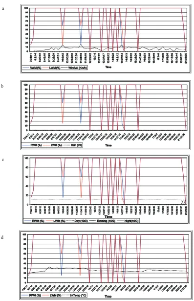
Fig. 8.Right/left window opening %: a – wind velocity vs. time, b – rain vs. time, c – vs. time of the day, and d – internal temperature vs. time of day.
c
first checks that a previous communication on the WindVDCh really exists on the relevant TEH, then that the time difference between current and immediately preceding communication is less than or equal to the sensor reading period (an input parameter for CCS). The assertion writes information about the check in a log file. The assertion was found always verified during the simulation. Other similar assertions were prepared for the other machines.
Snapshots from real execution
Assertions are normally excluded from the production build of an H-CRSM system. A special assertion, though, which simply stores the occurrence (time and value) of all events and reactions of CCS in a system history log file, was kept in the real-time operation in order to take snapshots from the real operation of the system.
Figures 8 depict the climatic behaviour of a particular PTU on a given day. On the chosen day some interesting external events (wind vs. rain) are sensed. The operation of the two window motor groups (RWM – right window mo-tor, LWM - left window motor) is represented against time of the day and respectively: wind velocity, rain, opening thresholds required by times of the day and the internal air temperature.
In Fig. 8a the day starts for the PTU at about 7:00 a.m., when both RWM/LWM are opened for less than 20%, and ends at 19:00, when RWM/LWM begin to close (they are fully closed at 21:30). At about 8:00 both the windows are fully opened (100%). Figure 8 shows that at 10:08, due to a wind peak, RWM, which is in front of wind, is opened less than 20%, whereas LWM (on the opposite side with respect to wind) is opened at 60%. The situation is exactly reversed at about 11:34. After that, there are moments where both windows are completely closedegat 12:22, although this action is not necessarily implied by wind velocity. As shown in Fig. 8b these instants effectively correspond to the presence of rain (rain bit true).
Figure 8c portrays the same information of RWM/ LWM vs. time of day thresholds as entered through the CCS GUI. As one can see, at 21:00 the PTU switches to night.
Finally, phenomena can be watched from the viewpoint of variations of the internal air temperature (Fig. 8d). In reality, the considered PTU registers, on the chosen day, internal temperature which is always beyond the admitted maximal value, already at the beginning of the day. Accordingly, the worst-case climatic conditions command the operation of the window motors. For instance, the fact that from the beginning of the day the windows get completely opened is a direct consequence of the sensed high internal temperature. However, rain and wind can temporarily become the most critical events to which the CCS, for safety, has to react.
CONCLUSIONS
1. The greenhouse Climate Control System (CCS) described in this paper is characterized by the use of a Java centred custom and time-sensitive component-based soft-ware architecture (H-CRSM), and by its character of being application-expert configurable. The user-friendly graphi-cal interface permits, for example, to configure the poly-tunnel units which are to be actively controlled and to enter threshold information which directs the CCS in the process of responding to climatic events.
2. Parameters which drive microclimate control are actually derived through experimental work and rely also on domain expert knowledge. In alternative, parameter values could be suggested by using specific models of greenhouse microclimates as described, for example, in Mirandaet al., 2006; Van Henten, 2003; Leeset al., 2005.
3. CCS realization is cost-effective with respect to the cost of the controlled greenhouse physical system. Its practical use does not require computer engineering competence. Configuration data, which tend naturally to be reusable, can be saved and restored instead of being re-entered at each start-up.
4. Current efforts are directed at: – improving data configuration,
– optimising the control strategy of the CCS,
– completing remote monitoring and control of the CCS through a smart phone.
5. Future directions which deserve further work are geared at:
– extending control to lateral and front/rear window motors in poly-tunnel units,
– enabling CO2and light radiation control,
– adding the automatic control of a darkening subsystem in selected poly-tunnel units,
– controlling the irrigation subsystem,
– adapting the system to hydroponics/aeroponics horti-cultures.
REFERENCES
Albright L.D., Gates R.S., Arvanitis K.G., and DrysdaleA.E., 2001.Environmental control for plants on earth and in space. IEEE Control Systems Magazine, October, 28-47. Caponetto R., Fortuna L., Nunnari G., Occhipinti L., and
Xibilia M.G., 2000.Soft computing for greenhouse climate control. IEEE Trans. On Fuzzy Systems, 8, 6, December, 753-760.
Critten D.L. and Bailey B.J., 2002. A review of greenhouse engineering developments during the 1990s. Agric. Forest Meteor., 112/1, 1-22.