A CLOSED-FORM NON- LINEAR SOLUTION FOR PLASTIC
FLANGE WRINKLING OF CIRCULAR PLATES IN DEEP
DRAWING PROCESS
M. Rezaiee-Pajand*, F. Moayyedian
School of Engineering, Ferdowsi University of Mashhad [email protected]
* Corresponding Author
(Received: July 27, 2009 – Accepted in Revised Form: July 15, 2010)
Abstract This paper deals with two-dimensional plane stress wrinkling model of a plastic annular plate. Based on energy method and the nonlinearity of strain-displacement law, a bifurcation function in polar coordinates is derived analytically. This technique leads to the critical conditions for the onset of the plastic wrinkling of flange during the deep drawing process. To find this solution, the Tresca yield criterion along with plastic deformation theory are employed. The material of the plate is assumed to behave perfectly plastic. This analytical closed-form solution is obtained by considering the nonlinearity of the material and geometry, simultaneously. The main advantage of the proposed solution is better agreement to the other researchers's experimental results. Moreover, the influence of the blankholder upon wrinkling, and also on the number of the generated waves, can be quantitatively predicted by the suggested scheme.
Keywords Energy method, Plastic wrinkling, Bifurcation function, Deep drawing process, Geometric non-linearity, Circular plate
ﻩﺪﻴﻜﭼ
ﺍﺭﺩ ﻳ ﻪﻟﺎﻘﻣ ﻦ ﻳ ﮔﺩﺭﻮﺧﮎﻭﺮﭼ ﻝﺪﻣﮏ ﻲﺪﻌﺑﻭﺩ ﻱ ﺭﺩ ﻳ ﻮﻘﻠﺣﻪﺤﻔﺻ ﮏ ﻱ
ﺘﺳﻼﭘ ﻴ ﮑ ﻲ ﺳﺭﺮﺑ ﻲ ﻣ ﻲ ﺩﻮﺷ
.
ﮊﺮﻧﺍﺵﻭﺭﺱﺎﺳﺍﺮﺑ ﻱ
ﺎﺠﺑﺎﺟﻥﻮﻧﺎﻗﻭ ﻳ
ﻲ ﺸﺸﮐ ﻲ ﻏﻴ ﻄﺧﺮ ﻲ ،ﻳ ﺍﻪﺧﺎﺷﻭﺩﻊﺑﺎﺗﮏ ﻱ
ﺒﻄﻗﺕﺎﺼﺘﺨﻣﺭﺩ ﻲ
ﺕﺭﻮﺻﻪﺑ
ﻠﺤﺗ ﻴﻠ ﻲ ﻣﺖﺳﺩ ﻪﺑ ﻲ
ﺁﻳ ﺪ
.
ﺍﻳ ﻨﮑﺗ ﻦ ﻴ ﺍﺮﺷﻪﺑﺮﺠﻨﻣ ﮏ ﻳ
ﺻﺎﺧﻂ ﻲ ﺍﺮﺑ ﻱ ﮔﺩﺭﻮﺧﮎﻭﺮﭼ ﻉﻭﺮﺷ ﻲ
ﺘﺳﻼﭘ ﻴ ﮏ ﺭﺩﺞﻨﻠﻓ
ﻃ ﻲ ﺍﺮﻓ ﻳ ﻤﻋﺶﺸﮐﺪﻨ ﻴ
ﻣﻖ ﻲ ﺩﻮﺷ
.
ﺍﺮﺑ ﻱ ﺍﻞﺣ ﻳ ﺭﻮﺌﺗﺎﺑﻩﺍﺮﻤﻫﺎﺳﺮﺗﻩﺩﺯﺎﺑﺯﺍﻪﻟﺎﺴﻣﻦ ﻱ
ﻐﺗ ﻴﻴ ﺘﺳﻼﭘﻞﮑﺷﺮ ﻴ
ﻩﺩﺎﻔﺘﺳﺍﮏ
ﻣ ﻲ ﺩﻮﺷ
.
ﻣﺽﺮﻓ ﻲ ﺘﺳﻼﭘﻼﻣﺎﮐﺕﺭﻮﺻﻪﺑ ﻪﺤﻔﺻﻪﮐﺩﻮﺷ ﻴ
ﺪﻨﮐﺭﺎﺘﻓﺭﮏ
.
ﺍﻳ ﻠﺤﺗﻞﺣﻩﺍﺭﻦ ﻴﻠ
ﻲ ﻏﺽﺮﻓﺎﺑ ﻴ ﻄﺧﺮ ﻲ
ﻥﺎﻣﺰﻤﻫﺭﻮﻃﻪﺑﻞﮑﺷﻭﺲﻨﺟﻥﺩﻮﺑ ﻳ
ﻣﺖﺳﺩﻪ ﻲ ﺁﻳ ﺪ
.
ﺮﺘﻤﻬﻣ ﻳ ﺰﻣﻦ ﻳ ﺍﺖ ﻳ ﺎﻨﺗﺎﺑﻥﺁﺏﻮﺧﻖﺑﺎﻄﺗﺵﻭﺭﻦ ﻳ
ﺑﺮﺠﺗﺞ ﻲ
ﺖﺳﺍﻥﻮﺘﻣﺭﺩﺩﻮﺟﻮﻣ
.
ﻨﭽﻤﻫ ﻴ ﺛﺎﺗﻦ ﻴ ﻭﺭﺪﻫﺎﺷﻩﺪﻧﺭﺍﺪﻬﮕﻧﺮ ﻱ
ﮔﺩﺭﻮﺧﮎﻭﺮﭼ ﻲ
ﻨﭽﻤﻫﻭ ﻴ ﻟﻮﺗﺝﺍﻮﻣﺍﺩﺍﺪﻌﺗﻦ ﻴ
ﻩﺪﺷﺪ
ﻣﺍﺭ ﻲ ﺍﺎﺑﻥﺍﻮﺗ ﻳ ﭘﺵﻭﺭﻦ ﻴ ﺩﺎﻬﻨﺸ ﻱ ﭘﻴ ﺑﺶ ﻴ ﺩﺮﮐﯽﻨ
.
1. INTRODUCTION
Wrinkling is considered as one of the critical defects in deep drawing, together with tearing, spring back and other geometric and surface defects. Contrary to fracturing, wrinkling can be treated as a recoverable defect even when they develop during the deep drawing process. Many investigators’efforts have been dedicated to predict the occurrence, location, and shape of the wrinkles,
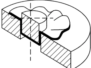
particular drawing-tool dimensions and blank thickness, there is a critical blank diameter/thickness ratio. Figure 3[3, 4] shows that the critical stress causes the plastic buckling of the annular part of the blank so that an undesirable mode of deformation ensues with the generated waves in the flange.
Many efforts have been made during the past years to meet the needs of press tool designers. In 1928, Geckeler [2] gave a mathematical analysis and two useful expressions for the case where no blankholder was used. He showed that the critical stress, at which buckling will occur, is
2 0
cr 2
E t 0.46
W
σ = . In this formula,
σ
cr is the critical stress in the flange when buckling occurs,t
is the blank thickness andW
shows the width of the flange. Also,E
0 is the buckling modulusdetermined by ,
) (
4 2 0
P E
EP E
+
= where
E
isYoung's modulus and
P
is the tangent modulus of the material. In addition, the number of waves or lobes, into which the flange buckles isW r n=1.65 m
, where
n
is the number of waves andr
m is the mean radius of the flange. Esser and Arend developed an empirical equation to fit data, which they obtained with annealed copper, brass and mild steel. Their equation reduces tob
−
a
=
4
.
35
t
,
where
b
is the blank radius anda
is the inner radius of the flange [3]. An outstanding approach by Baldwin and Howald [5] in 1947 was developed by applying Geckeler's equations for practical ends with predictions of the limiting reductions in diameter for given conditions of metal and temper, etc. [3]. In 1956, Geckeler's equations were extended by Senior. Based on his study, energy expended in the flange by the circumferential stress was equated to the energy dissipated in buckling the flange, so that the theory could be applied for buckling under both constant load and spring-loaded blankholders [3]. Since Senior only used a one-dimensional buckling model, the flange was approximated as a number of linked struts and a pressure distribution was assumed for the boundary condition at the inner edge, which seems not to be very realistic. Comment on this work wasmade by Alexander [3]. Most of the previous studies on this subject are based on the one-dimensional buckling model, hence those results can be expected to have a good approximation only when the width of the flange is small compared to the radius of the blank, that is W=b−a<<b,or
1.
ξ <<
It can be easily verified that the reductionin outer diameter is 100ξ
) 2 (
200 =
+ =
W r
W R
m
[3] Alternatively, Yu and Johnson [3] used the energy method in elastic stability theory as a basis for plastic wrinkling analysis. They proposed an equation for balancing the work done by stresses induced in the flange and the strain energy due to bending in plastic wrinkling. According to their analysis, the onset of plastic wrinkling is governed
by 0
p E t 3 H(m, n)
Y b <2 F (m, n)
, where the entities
H
and
F
p are functions of the wave number and the flange dimension, respectively. The wave numbers computed from the last equation are lower than those from experimental results and also those obtained from Geckeler's and Senior's equations [6]. The reader is referred to work of Yu and Johnson, Zhang [7] and Yu for further details of their approaches. Subsequently, Yossifon and Tirosh [8] extended the analysis to investigate the fluid pressure as an additional energy term in their equation. The analysis reported so far are either too simplistic, which are based on one-dimensional beam theory or on two-one-dimensional elastic-based rigid-plastic stability theory. The one-dimensional beam theory type of formulations ignored the effects of shear stresses and higher-order terms in the stability equation and therefore, cannot fully describe the flange wrinkling phenomena of a deep– drawn cup. While the two-dimensional formulations have been entirely relied on the elastic-based rigid-plastic stability equation of plates, most investigators simply replaced the Young's modulus in buckling analysis that can be quite inadequate [4].A bifurcation function was proposed by Hutchinson [9, 10] based on Hill general theory of uniqueness and also bifurcation in elastic-plastic solids [11,12]. This function is given as:
,
)
(
2
1
, , 0
ds
w
w
t
N
M
buckling displacement,
t
shows the thickness of the plate, Nij presents the force resultants, Mij is the couple resultants (per unit width),κ
ij denotes the curvature tensor andε
ij0 is the stretch strain tensor. This bifurcation function contains the total energy for wrinkling occurrence. In other words, for some non-zero displacement fields, the state of0
=
F
corresponds to the critical conditions for wrinkles to occur [13-15].Figure 1. Deep drawing process with cylindrical punch
Figure 2. The model of the flange as an annular plates with radial stress distribution in its inner edges
Figure 3. The generated waves in the flange
In this paper, the bifurcation function is found using energy method along with the Von Karman kinematic relation. To have a closed-form analytical solution, the Tresca yield criterion and also plastic deformation theory are used. A complete form of the function (1) is suggested for the perfectly plastic materials. The results show that the proposed solutions for the critical conditions of the onset of the wrinkling have a better agreement than the other available experimental findings.
2. PLATE COORDINATE SYSTEM
In order to derive the bifurcation functional, the energy method can be used. It is proper to utilize the polar coordinate for the plate. This coordinate system is set in the middle surface of the un-deformed (pre-buckled) annular plate. All the points in the plate are defined by coordinates
r
and
θ
, lying in the middle surface of the un-deformed body and alsoz
coordinate normal to this surface.2.1. The Lagrangian Strain At first, the strain-displacement relation is discussed. The displacement components,
u
,v
andw
, are given below [7]:
=
∂
∂
−
=
∂
∂
−
=
)
,
(
)
1
(
)
,
(
)
,
(
0 0
θ
θ
θ
θ
r
w
w
w
r
z
r
v
v
r
w
z
r
u
u
(2)
where,
u
0 andv
0 are the displacements in the middle plane of the plate, inr
andθ
directions, respectively. The buckling displacement normal to the plane of the plate in thez
direction is shown byw
. The nonlinear Lagrangian strain tensor is as follows [7]:)
(
2
1
, , ,
,i j m i m j
ij
=
u
+
u
+
u
u
By neglecting some nonlinear terms and using Eq. (3), the Von Karman kinematic relation in polar coordinates can be written in below form [16]:
∂ ∂ ∂ ∂ + − ∂ ∂ + ∂ ∂ =
∂ ∂ + ∂
∂ + =
∂ ∂ + ∂ ∂ =
] ) 1 )( ( ) 1
[( 2 1
) 1 ( 2 1 1
) ( 2 1
2 2
θ θ
ε
θ θ
ε ε
θ θθ
w r r w r v r v u r
w r v r r u
r w r
u
r rr
(4)
∂ ∂ − ∂ ∂
∂ −
∂ ∂ ∂ ∂ + − ∂ ∂ + ∂ ∂ =
∂ ∂ + ∂ ∂ − ∂ ∂ + ∂ ∂ + =
∂ ∂ − ∂ ∂ + ∂ ∂ =
) 1 (
] ) 1 ( ) ( 1
[ 2 1
) 1 ( ) 1 ( 2 1 1
) ( 2 1
2
0 0 0
2 2 2
0 0
2 2 2 0
θ θ
θ θ
ε
θ θ
θ ε
ε
θ θθ
w r r
w r z
w r r w r v r v u r
w r r w r z w r v r r u
r w z r w r
u
r rr
(5)
For simplicity, the following Lagrangian strain tensor and parameters are used in this work:
ij ij
ij
ε
z
κ
ε
=
0+
(6)where,
∂ ∂ ∂ ∂ + − ∂ ∂ + ∂ ∂ =
∂ ∂ + ∂ ∂ + =
∂ ∂ + ∂ ∂ =
] ) 1 ( ) ( 1
[ 2 1
) 1 ( 2 1 1
) ( 2 1
0 0 0 0
2 0
0 0
2 0
0
θ θ
ε
θ θ
ε ε
θ θθ
w r r w r
v
r v u
r
w r v
r r u
r w r
u
r rr
(7)
And
∂ ∂ + ∂ ∂
∂ − =
∂ ∂ − ∂ ∂ − =
∂ ∂ − =
θ θ
κ
θ κ
κ
w r r
w r
w r r w r
r w
2 2
12
2 2
2 22
2 2
11
1 1
1
1 (8)
2.2. Constitutive Equation In a deep drawing process, the flange has large deflection and also contains the plastic deformation. Therefore, the plastic behavior of the material and geometric
non-linearity of the structure should be considered, simultaneously. To solve this plate problem, the stress-strain relationships are required. There are two types of theory in plasticity. The first one is the deformation theory which neglects the loading history dependency in the development of the stress-strain relationships. In fact, this theory assumes that the stress state,
σ
ij, can be determined uniquely from the strain state,ε
ij , and also plastic strain,ε
ijp, as long as the plastic deformation continues. Because of its relatively simplicity; the deformational theory has been used extensively in the engineering practice for solving elastic-plastic problems. The general validity of the deformation theory in plasticity is limited to the monotonically increasing loading in which:(1) the stress components are increased nearly proportionally in a loading process, known as proportional loading; and (2) no unloading occurs.The second way of utilizing the elasto-plastic analysis is based on the incremental theory. This kind of the strategy is mostly used in the numerical material non-linear techniques. In contrast to the deformation theory, the loading path dependency is assured in the incremental theory [8]. It should be reminded that the loading in the annular plate has the proper conditions needed for the deformation theory. In order to find a closed-form non-linear solution for the plastic flange wrinkling of the circular plate in the deep drawing process, it is preferred to use the deformation theory rather than the incremental plasticity theory. The constitutive equation for the three-dimensional solid problems used in the deformation theory is given below:
kl ep ijkl
ij
C
ε
σ
=
(9) where,C
ijklep , for the perfectly plastic materials, is determined by the following relationship [17-20]:tu e rstu rs
e pqkl pq mn e
ijmn e
ijkl ep
ijkl f
C f
C f f C
σ σ
σ σ
∂ ∂ ∂
∂ ∂
∂ ∂
∂
− =C
C (10)
coefficient of the hook’s law. Due to the simplicity of one side of the Tresca yield surface, this function is utilized in this study. According to the loading, one of the stresses (
σ
r) is positive and the other is negative (σ
θ). In this state of stress, the Tresca yield function of the second stress region is a proper one. In other words, the following linear function is used:0
=
−
−
=
Y
f
σ
rσ
θ (11) In this function, Y is the uniaxial yield stress. Expanding Eq. (9) for i, j,k =1,2,3, simplifying the results for the plane stress problem (i.e.0
23 13
33
=
σ
=
σ
=
σ
) and using Eqs. (10) and(11), a simple plane stress elastic-plastic constitutive equation is found. In other words, the expanded form of Eq. (9) has the following appearance:
+ −
−
− −
=
12 22 11
12 22 11
) 1 ( 2 0 0
0 ) 1 ( 2 ) 1 ( 2
0 ) 1 ( 2 ) 1 ( 2
γ ε ε
ν ν
ν
ν ν
τ σ σ
E E
E
E E
(12)
2.3. Strain Energy The density of the strain energy for the plate,
U
0 , can be written as follows [16]:ij ij ij
kl ep ijkl
ij kl ep ijkl ij
ij
C
d
C
d
U
ij ij
ε
σ
ε
ε
ε
ε
ε
σ
ε ε
2
1
2
1
0 0
0
=
=
=
=
∫
∫
(13)
By integrating the density of the strain energy over the volume of the flange, and assuming the plane stress state, the strain energy can be written in the following form:
∫ ∫ ∫
∫ ∫ ∫
− −
+ +
= =
b
a h
h
r r rr
rr b
a h
h ij ij
d dr r dz d
dr r dz U
π
θ θ θθ θθ π
θ ε
σ ε σ ε σ
θ ε
σ
2
0 2
2 2
0 2
2
) 2
( 2 1
2 1
(14)
On the other hand, the force (
N
ij) and moment resultant (M
ij) are calculated from the below equations:
= =
∫
∫
− −
2
2 2
2
) , , ( ) , , (
) , , ( ) , , (
h
h
r rr
r rr
h
h
r rr
r rr
zdz M
M M
dz N
N N
θ θθ θ
θθ
θ θθ θ
θθ
σ σ σ
σ σ σ
(15)
These values and also the strain from Eq. (5) are substituted in Eq. (14). After some simplifications, the strain energy in terms of the displacements can be written in the following from:
θ θ
θ
θ θ
θ θ
θ
θ θ
θθ θθ
π
dzrdrd w
r r
w r M
w r r w r v r v u r N
w r r w r M w r v r r u N
r w M r w r
u N U
r r
b
a
rr rr
)} 1 (
1
] ) 1 ( ) ( 1
[ 2 1
) 1 ( 1 ] ) 1 ( 2 1 1 [
) ( ] ) ( 2 1 [ { 2 1
2
0 0 0
2 2 2
0 0
2
0
2 2 2
0
∂ ∂ − ∂ ∂
∂ −
∂ ∂ ∂ ∂ + − ∂ ∂ + ∂ ∂ +
∂ ∂ + ∂ ∂ −
∂ ∂ + ∂ ∂ +
+ ∂ ∂ − ∂ ∂ + ∂ ∂
=
∫ ∫
(16)
Substituting Eq. (6) in Eq. (9) and also using the results of Eq. (16), the force and moment resultants are found in terms of the displacement fields. The result is given below:
=
+ =
= =
+ =
=
∫
∫
∫
∫
+
− +
−
+
− +
−
kl ep ijkl
h
h
kl ij ep ijkl h
h ij ij
ij ep ijkl
h
h
kl ij ep ijkl h
h ij ij
C h
dz z z C
dz z M
C h
dz z C
dz N
κ
κ ε σ
ε
κ ε σ
12
) (
) (
3
2
2
0 2
2 0
2
2
0 2
2
(17)
θ θ θ θ θ θ θ θ θ θ θ θ π π rdrd w r r w r v r v u r C w r v r r u r w r u C w r v r r u C r w r u C h rdrd w r r w r C w r r w r r w C w r r w r C r w C h U ep ep ep b a ep ep ep ep b a ep } ]) ) 1 ( ) ( 1 [ 2 1 ( 4 ] ) 1 ( 2 1 1 ][ ) ( 2 1 [ 2 ] ) 1 ( 2 1 1 [ ] ) ( 2 1 [ { 2 1 } )] 1 ( 1 [ 4 )] 1 ( 1 )[ ( 2 )] 1 ( 1 [ ) ( { 12 2 1 2 0 0 0 1212 2 0 0 2 0 1122 2 2 0 0 2222 2 0 2 2 0 1111 2 2 1212 2 2 2 2 1122 2 2 2 2222 2 0 2 2 2 1111 3 ∂ ∂ ∂ ∂ + − ∂ ∂ + ∂ ∂ + ∂ ∂ + ∂ ∂ + ∂ ∂ + ∂ ∂ + ∂ ∂ + ∂ ∂ + + ∂ ∂ + ∂ ∂ + ∂ ∂ − ∂ ∂ ∂ + ∂ ∂ + ∂ ∂ ∂ ∂ + ∂ ∂ + ∂ ∂ + ∂ ∂ + =
∫ ∫
∫ ∫
(18)2.4. External Work The external force (
N
ˆ
ij) is acting in the middle plane of the plate (i.e.z
=
0
). Considering this force, and also using Eq. (6), lead to the strain tensor (ε
ij=
ε
ij0). It is easy to show that the external work can be written in the following form:∫ ∫
∫ ∫
∫ ∫
+ + = = = b a b a ij ij b a ij ij E rdrd N N N rdrd N rdrd N W π π π θ ε ε ε θ ε θ ε 2 0 0 12 12 0 22 22 0 11 11 2 0 0 2 0 ] ˆ 2 ˆ ˆ [ ˆ ˆ (19)Assuming,
N
ˆ
ij=
h
σ
ij, and substituting Eq. (7) into Eq. (19), lead to the following relationship:θ θ θ θ θ π rdrd w r r w r v r v u r N w r v r r u N r w r u N W b a E ]) ) 1 ( ) ( 1 [ 2 1 ( ˆ 2 ] ) 1 ( 2 1 1 [ ˆ ] ) ( 2 1 [ ˆ [ 0 0 0 12 2 0 0 22 2 0 2 0 11 ∂ ∂ ∂ ∂ + − ∂ ∂ + ∂ ∂ + ∂ ∂ + ∂ ∂ + + ∂ ∂ + ∂ ∂ =
∫ ∫
(20)It should be noted that the plastic stress distribution in the flange before the wrinkling is
similar to the axisymmetric problem, (i.e.
v
=
0
and
=
0
∂
∂
θ
) [3,18]: < − = > = 0 ] 1 ) [ln( 0 ) ln( r b Y r b Y r θ σ σ (21)
Utilizing this plastic stress distribution, the external work in Eq. (20) can be written as below:
] ) 1 ( 2 1 1 [ ] ) ( 2 1 [ [ 2 0 0 2 0 2 0 θ θ σ σ θ π ∂ ∂ + ∂ ∂ + + ∂ ∂ + ∂ ∂ =
∫ ∫
w r v r r u h r w r u h W b a r E (22)2.5 The Total Potential Energy Having the strain energy and the external work in hand, the total potential energy function can be formed:
E
W U −
=
π (23) Using Eq. (18) and Eq. (22), the nonlinear bifurcation function can be written as below:
Another important point in establishing the critical conditions for onset of the wrinkling is assuming a proper displacement field. In fact, the essential or geometric boundary conditions of the plate must be satisfied by the assumed displacement fields (
u
,
v
,
w
). For instance, a suitable displacement field can be expressed as a function of the radial coordinate,r
, and the polar angle,θ
. In this work, it is assumed that the displacement fields of the flange for a deep drawn cup have the following form [21, 22]: = = + − = θ θ θ θ θ θ n r e r v n r d r u n a r c r w sin ) , ( cos ) , ( ) cos 1 ( ) ( ) , ( 0
0 (25)
where,
c
,d
ande
are constants andn
is the wave number. It is obvious that any admissible bifurcation mode in Eq. (25) satisfies the kinematical boundary conditionsu
,
v
≠
0
and0
=
w
at the inner edge (r
=
a
) and also the kinematical constraint:w
(
r
,
θ
)
≥
0
,u
0(
r
,
θ
)
≥
0
,0
)
,
(
0
r
θ
≥
v
fora
≤
r
≤
b
. After substituting Eq. (21) and Eq. (25) into the function (24) and consideringm
b
a
=
, one can write the following relationship in terms of the number of generated waves (n): ) , ( 8 ] ) , , ( ) , , ( ) , , ( ) , , ( ) , , ( ) , , ( [ ) 1 ( 128 1 ) , , ( ) 1 ( 96 2 2 2 2 2 2 4 2 2 2 2 3 n m L Y c b t d c n m K e c n m J de n m I e n m H d n m G c n m F b tE n m E E c t ep ep ep ep ep ep ep ep π ν ν ν ν ν ν ν π ν ν π π + + + + + + − − − = (26) where, )] 1 ( 4 ) 1 )[( 1 ( 16 ) , , ( )] 1 )( 1 ( 35 [ )] 1 ( 40 ) ln( 20 ) 1 ( 10 )[ 3 ( ])} 1 ) ln( 12 ) 1 ( 8 )[ 1 ( 3 { ) , , ( ) 1 )( 1 ln( 6 ] 2 ) ) ( ln )( 1 ( ) 1 ( [ 4 ] 3 ) 1 ( ln 2 4 )[ 1 ( ) , , ( 2 2 2 2 2 2 4 4 2 2 2 2 4 2 ν ν ν ν ν ν ν ν ν ν ν ν + + − − = − + + − + + − − + − + + − + = + + + − + + − − + − + + − + = n m n m G m n m m m m m n m m m m m n m F m n m m m n m m m n m E ep ep ep + − + − + + = + + + − − − = + − = + − = + − = ] 1 ) 1 ) ( ln 2 [( 3 } 2 1 ] 2 1 ) 1 ln( )) 1 {[(ln( 2 ) , ( )] 1 )( 1 ( 2 ) 1 )( 1 )[( 1 ( 32 ) , , ( ) 1 )( 1 ( 32 ) , , ( ) 1 )( 1 ( 64 ) , , ( ) 1 )( 1 ( 16 ) , , ( 2 2 2 2 2 2 2 2 2 m m n m m m n m L m n m m n m K n m n m J n m n m I n m n m H ep ep ep ep ep ν ν ν ν ν ν ν ν ν (27)
It is worth writing the suggested function in the below matrix form:
{
}
= e d c c M M M M M M M M M M e d c c 2 44 43 42 34 33 32 24 23 22 11 2 0 0 0 0 0 0π (28)
where, − − = − − = = − = − − = = − − = = − − = + − = ) , , ( ) 1 ( 128 1 ) , , ( ) 1 ( 128 1 2 1 ) , , ( ) 1 ( 8 ) , , ( ) 1 ( 128 1 2 1 ) , , ( ) 1 ( 128 1 2 1 ) , , ( ) 1 ( 128 1 ) , ( 8 ) , , ( ) 1 ( 96 2 2 44 2 2 43 34 2 2 33 2 2 42 24 2 2 32 23 2 2 22 2 2 3 11 ν ν π ν ν π ν ν π ν ν π ν ν π ν ν π π ν ν π n m H b tE M n m I b tE M M n m G b E t M n m J b tE M M n m K b tE M M n m F b tE M n m L Y t b n m E E t M ep ep ep ep ep ep ep ep (29)
The critical conditions for onset of the wrinkling are written below:
= ∂ ∂ = ∂ ∂ = = 0 )] ( [ 0 ) ( ij ij M Det n n M Det π π (30)
The first relation in Eq. (30) leads to
M
11M
33(
M
22M
44−
M
242)
=
0
, ifM
33=
0
or2 24 44
22
M
M
wrinkling becomes
M
11=
0
.Wrinkling will occur when the following equation is satisfied:) , , ( ) , , ( ) 1 ( 12 2 2 2 ν ν
ν H mn
n m G b t E Y ep ep − −
= (31)
) , , ( ) , , ( ) 1 ( 12 2 ν ν ν n m G n m H b t Y E ep ep − −
= (32)
If, ) , , ( ) , , ( ) 1 ( 12 2 ν ν ν n m G n m H b t Y E ep ep − −
< (33)
2.6 Plastic Wrinkling With Blankholder
According to Figure 1, when a spring-type blankholder is used, it provides a lateral load proportion to the lateral deflection of the annular plate. By assuming the spring coefficient of the Blankholder (
K
), the total spring stiffness has the following form:)
(
b
2a
2K
S
=
π
−
(34) If the effects of the blankholder are considered, the strain energy function can be established as below:) ( 2 1 } ]) ) 1 ( ) ( 1 [ 2 1 ( 4 ] ) 1 ( 2 1 1 ][ ) ( 2 1 [ 2 ] ) 1 ( 2 1 1 [ ] ) ( 2 1 [ { 2 1 } )] 1 ( 1 [ 4 )] 1 ( 1 )[ ( 2 )] 1 ( 1 [ ) ( { 12 2 1 2 max 2 max 0 2 max 0 2 0 0 0 1212 2 0 0 2 0 1122 2 2 0 0 2222 2 0 2 2 0 1111 2 2 1212 2 2 2 2 1122 2 2 2 2222 2 0 2 2 2 1111 3 w v u K rdrd w r r w r v r v u r C w r v r r u r w r u C w r v r r u C r w r u C h rdrd w r r w r C w r r w r r w C w r r w r C r w C h U ep ep ep b a ep ep ep ep b a ep + + + ∂ ∂ ∂ ∂ + − ∂ ∂ + ∂ ∂ + ∂ ∂ + ∂ ∂ + ∂ ∂ + ∂ ∂ + ∂ ∂ + ∂ ∂ + + ∂ ∂ + ∂ ∂ + ∂ ∂ − ∂ ∂ ∂ + ∂ ∂ + ∂ ∂ ∂ ∂ + ∂ ∂ + ∂ ∂ + ∂ ∂ =
∫ ∫
∫ ∫
θ θ θ θ θ θ θ θ θ θ θ θ π π (35)∫ ∫
∫ ∫
∫ ∫
∂ ∂ + ∂ ∂ + + ∂ ∂ + ∂ ∂ + + + + ∂ ∂ ∂ ∂ + − ∂ ∂ + ∂ ∂ + ∂ ∂ + ∂ ∂ + ∂ ∂ + ∂ ∂ + ∂ ∂ + ∂ ∂ + + ∂ ∂ + ∂ ∂ + ∂ ∂ − ∂ ∂ ∂ + ∂ ∂ + ∂ ∂ ∂ ∂ + ∂ ∂ + ∂ ∂ + ∂ ∂ = b a r ep ep ep b a ep ep ep ep b a ep rdrd w r v r r u r w r u h w v u K rdrd w r r w r v r v u r C w r v r r u r w r u C w r v r r u C r w r u C h rdrd w r r w r C w r r w r r w C w r r w r C r w C h π θ π π θ θ θ σ σ θ θ θ θ θ θ θ θ θ θ θ θ π 2 0 2 0 0 2 0 2 max 2 max 0 2 max 0 2 0 0 0 1212 2 0 0 2 0 1122 2 2 0 0 2222 2 0 2 2 0 1111 2 2 1212 2 2 2 2 1122 2 2 2 2222 2 0 2 2 2 1111 3 ]} ) 1 ( 2 1 1 [ ] ) ( 2 1 [ { [ ) ( 2 1 } ]) ) 1 ( ) ( 1 [ 2 1 ( 4 ] ) 1 ( 2 1 1 ][ ) ( 2 1 [ 2 ] ) 1 ( 2 1 1 [ ] ) ( 2 1 [ { 2 1 } )] 1 ( 1 [ 4 )] 1 ( 1 )[ ( 2 )] 1 ( 1 [ ) ( { 12 2 1 (36)Consequently, the total potential energy of whole structure can be utilized from the equation (36). The displacements
u
0,v
0 andw
can be assumed similar to Eq. (25). The maximum deflections have the following values:It is easy to show that the following equations are also held: + − = − − = − = − = − = − = . 1 1 2 ) ( 4 ) ( 2 2 1 , ) 1 ( 2 1 ) ( 2 2 1 , ) 1 ( 2 1 ) ( 2 2 1 2 2 2 2 2 2 max 2 2 2 2 2 2 2 max 0 2 2 2 2 2 2 2 max 0 m m S c a b c a b S w K m e S b e a b S v K m d S b d a b S u K π π π π π π (38)
Based on these equations, the energy stored in the spring-type blankholder can be written as below:
2 2 2 2 2 max 2 max 0 2 max 0 1 1 2 ) ( ) 1 ( 2 1 ) ( 2 1 c m m S e d m S w v u K + − + + − = + + π π (39)
As a result, the bifurcation function has the following form: 2 2 2 2 2 2 2 2 2 2 4 2 2 2 2 3 1 1 2 ) ( ) 1 ( 2 1 ) , ( 8 ] ) , , ( ) , , ( ) , , ( ) , , ( ) , , ( ) , , ( [ ) 1 ( 128 1 ) , , ( ) 1 ( 96 c m m S e d m S n m L Y c b t d c n m K e c n m J de n m I e n m H d n m G c n m F b tE n m E E c t ep ep ep ep ep ep ep ep + − + + − + + + + + + + − − − = π π π ν ν ν ν ν ν ν π ν ν π π (40)
It is more suitable to write this function in the below matrix form:
{
}
= e d c c M M M M M M M M M M e d c c 2 44 43 42 34 33 32 24 23 22 11 2 0 0 0 0 0 0π (41)
where, ) , , ( ) 1 ( 8 ] ) 1 ( 1 ) , , ( ) 1 ( 128 1 [ 2 1 ] ) 1 ( 1 ) , , ( ) 1 ( 128 1 [ 2 1 ) , , ( ) 1 ( 128 1 1 1 2 ) , ( 8 ) , , ( ) 1 ( 96 2 2 33 2 2 2 42 24 2 2 2 32 23 2 2 22 2 2 3 11 ν ν π π ν ν π π ν ν π ν ν π π π ν ν π n m G b E t M m S n m J b tE M M m S n m K b tE M M n m F b tE M m m S n m L Y t b n m E E t M ep ep ep ep ep ep − = − + − − = = − + − − = = − − = + − + + − = − − = − − = = ) , , ( ) 1 ( 128 1 ) , , ( ) 1 ( 128 1 2 1 2 2 44 2 2 43 34 ν ν π ν ν π n m H b tE M n m I b tE M M ep ep (42)
The critical conditions for onset of the wrinkling are given below:
= ∂ ∂ = ∂ ∂ = = 0 )] ( [ 0 ) ( ij ij M Det n n M Det π π (43)
This equation yields M11M33(M22M44 −M242)=0, if
M
33=
0
orM
22M
44−
M
242=
0
, which results ton
=
0
. Therefore, the critical condition to obtain the onset of the wrinkling becomesM
11=
0
. As a final result, it is found that the critical condition for the plastic buckling is the state ofπ
=
0
. This equation leads to the following value for the yield stress: ep ep H E v t b m m D S G Y ) 1 ( ) ( 3 1 1 ) 2 ( 4 2 2 2 − + − + −= π (44)
By assuming
D
S
=
ψ
, the following simplifiedresult will be in hand:
m m G H b t Y E ep ep + − + − − = 1 1 ) 2 ( 4 ) 1 ( 3 2 2 ψ π
ν (45)
If
π
f
0
, there will be a safe domain with no wrinkling [13-15]. To reach this state, Eq. (45) should change to the following condition:m m G H b t Y E ep ep + − + − − < 1 1 ) 2 ( 4 ) 1 ( 3 2 2 ψ π
ν (46)
3. RESULTS AND DISCUSSIONS
The assumed properties of steel are E =200Gpa
first condition of Eq. (30) will yield in
=
0
∂
∂
n
Y
. This equation has 5 roots for
n
, but only one of them is logical and also located in the range of (b
a
−
1
). In Figure 4,n
versus (b
a
−
1
) is shown and compared with Yu's and the experimental results [3].0 0.05 0.1 0.15 0.2 0.25 0.3 0.35 0.4 0
2 4 6 8 10 12 14 16 18
1 - a / b
n
Present Result Yu's Result Experimental Results
Figure 4. The number of the generated waves in the plastic flange wrinkling of the annular plate
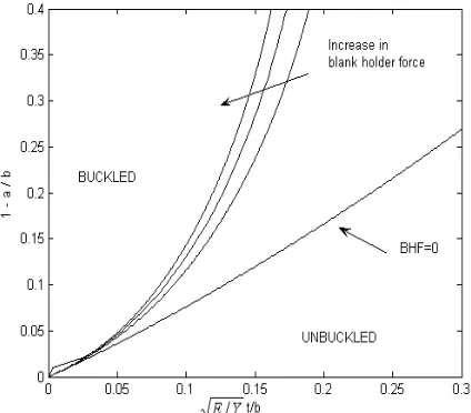
Figure 5. The wrinkling limitation of the flange
After finding
n
cr , by substituting it into Eq. (31),cr
Y is also found. In Figure 7, b t Y
E versus (
b
a
−
1
)is shown and compared with the available
solutions [2,3,6]. Furthermore, the critical conditions of the onset of the wrinkling for steel and aluminum can be compared by substituting their properties into Eq. (31) and Eq. (32).
Figure 6. Comparing wrinkling limitation of the steel and aluminium
Figure 7. Number of the generated waves in the flange
It is interesting to note that a good agreement of the suggested non-linear solution with the experimental one is observed in Figure 4. The wrinkling limitation of the flange is also found. A comparison between the current study results and those from the Geckeler and Senior [2,6] are also shown in Figure 5. Geckeler's result is a good approximation for small values of (
b
a
−
the flange increases. Moreover, Yu's results are curved shapes, which are the envelopes of the curves for many
n'
s
. It is worth emphasizing that explicit determination of the boundary of the buckling range is hard. In fact, to shown
cr andcr
Y
in the diagrams, numerical approximation and interpolations are usually used.Figure 8. Limitation of the plastic wrinkling
However, in the current study more exact expressions for
n
cr andY
cr are obtained without needs for any approximations or interpolations. It should be added that in this study, Y is in the state of the maximum hoop stress σθcr. According to Figure 6, and with the constant value of (b
a
−
1
), it is observed that the aluminum wrinkles under the lower loads than the steel. Finally, as it can be seen in Figure 7 and 8, the blankholder has influences on the number of the wrinkles and also limitation of the wrinkling. For the constant value of (b
a
−
1
),it is observed that increasing of the blankholder force increases the number of the waves and also increases the limitation of the forming without wrinkling.
4. CONCLUSIONS
Using energy method, the plastic wrinkling of the flange in the deep drawing process has been studied analytically. The proposed bifurcation function is more general than the one previously found. The nonlinearity of both the material and geometry are considered in the deriving of this bifurcation function. A closed-form analytical solution is formed based on the Tresca yield criterion and also the use of the plastic deformation theory. It is assumed that the materials behave perfectly plastic. The suggested technique leads to the critical loads and number of generated waves. Moreover, the analytical results of this paper have a good agreement with the experimental findings.
Nomenclature
ij
N Force resultants
ij
M Couple resultants
ij
κ
Curvature tensor0 ij
ε
Stretch strain tensor F Bifurcation functionalu
,v
In-plane displacement fieldw
Wrinkling displacementn
The wave numberij
ε
Lagrangian strainE
Young’s modulus of elasticityν
Poission’s ratioe ijkl
C
Elastic coefficient matrixep ijkl
C
Plastic coefficient matrixf
Yield criterionY
Yield stress0
U
Density of strain energyU
Strain energyE
W
External workπ
Total potential energyS
Blankholder forceK
Stiffness of the blankholdert
Thickness of the platea
Inner radius of the flange b Outer radius of the flangem
5. REFERENCES
1. Sivasankaran, S., Narayanasamy, R., Jeyapaul, R. and Lognathan, C., ‘Modelling of wrinkling in deep drawing of different grades of annealed commercially pure aluminum sheets when drawn through a conical die using artificial neural network’, Materials and Design, Vol. 30, (2009), 3193-3205.
2. Geckeler, J.W. "Pastche knichen der wandung Von Holzheimer und einige andere faltungserscheinungen", Angewandte Mathematick und Mechanik, Vol. 8, (1928), 341-52.
3. Yu, T. X. and Johnson, W., “The buckling of annular plates in relation to deep- drawing process” International Journal of Mechanical Sciences, Vol. 24, (1982), 175-88.
4. Chu, E., and Xu, Y., “An elasto-plastic analysis of flange wrinkling in deep drawing process”, Journal of Mechanics and Physics of Solids, Vol. 43, (2001), 1421-1440.
5. Baldwin W.M. and Howald T.S., ‘Folding in the cupping operation’, Transactions of American Society for Metals, Vol. 38, (1947), 757-88. 6. Senior, B.W. "Flange wrinkling in deep drawing
operation", Journal of Mechanics and Physics of Solids, Vol. 46, (1956), 4-235.
7. Zhang L.C. and Yu T.X., The plastic wrinkling of an annular plate under uniform tension on its inner edge, International Journal of Solids Structures, Vol. 24(5), (1988),497-503.
8. Yossifon S. and Tirosh J., The maximum drawing ratio in hydroforming processes, Journal of Engineering for Industry, Vol. 112, (1990), 47-56. 9. Hutchinson, J.W., "Plastic buckling",Advances in
Applied Mechanics, Vol. 67 (1974), 14-16. 10. Hutchinson, J.W. and Neale, K.W., "Wrinkling of
curved thin sheet metal", in Proceedings of International Symposium on Plastic Instability,
Consider Memorial (1841-1914), Paris, France, (Sep, 1985).
11. Hill, R., "A general theory of uniqueness and stability in elastic / plastic solids" , Journal of
Mechanics and Physics of Solids, Vol. 6, (1958), 6-236.
12. Hill, R., "Bifurcation and uniqueness in nonlinear mechanics of continua", Society of Industrial Applied Mathematics, (1961), 236-274.
13. Wang, C., Kinzel G., and Altan T., “Wrinkling criterion for anisotropic shell with compound curvatures in sheet forming”, International Journal of Mechanical Sciences, Vol. 36, (1994), 945-960. 14. Magalhaes Corria, J. P. De, and Ferron G.,
"Wrinkling prediction in the deep-drawing process of anisotropic metal sheets", Journal of Materials and Processing Technology, Vol. 155-156 (2004), 1604-1610.
15. Magalhaes Corria, J. P. De, and Ferron G., "Wrinkling of anisotropic metal sheets under deep-drawing analitical and numerical study", Journal of Materials and Processing Technology, Vol. 155-156 (2004), 1604-1610.
16. Reddy, J. N., ‘Energy Principles and Variation Methods in Applied Mechanics’, John Wiley & Sons, (2002).
17. Chen, W.F. and Zhang, H. "Structural Plasticity Theory, Problems, and CAE software", Springer-Verlag, New York, (1990).
18. Chakrabarty J., Theory of plasticity, New York, McGraw-Hill book Company.
19. Hill R., The mathematical theory of plasticity, New York, Oxford University press, 1950.
20. Khan, A. and Hung, S. "Continuum theory of plasticity", John Wiley & sons, (1995).
21. Tomita Y., Shindo A. and Fatnassi A., “Bounding approach to the bifurcation point of annular plates with non-associated flow rule subjected to uniform tension at their outer edges”, International Journal of Plasticity, Vol. 4, (1988), 251-263.