Please cite this article as: G. Shafabakhsh, M. Motamedi, Sensitivity Analysis of Road Actual Conditions to Evaluate the Optimal Positioning of Geogrid Using Finite Elements and Dynamic Methods , International Journal of Engineering (IJE), TRANSACTIONS C: Aspects Vol. 29, No. 9, (September 2016) 1235-1241
International Journal of Engineering
J o u r n a l H o m e p a g e : w w w . i j e . i rSensitivity Analysis of Road Actual Conditions to Evaluate the Optimal Positioning
of Geogrid Using Finite Elements and Dynamic Methods
G. Shafabakhsh, M. Motamedi*
Civil Engineering Department, Semnan University, Semnan, Iran
P A P E R I N F O
Paper history:
Received 30 May 2016
Received in revised form 04 August 2016 Accepted 25 August 2016
Keywords:
Geogrids Flexible Pavements Finite Element Software Optimal Positioning Dynamic Responses
A B S T R A C T
Roads are subjected to vehicle traffics with different loads and velocities. Geogrid reinforcement is of the best methods for road improvement due to the ease of construction, delay in damage development and financial efficiency. This study evaluates pavement response under different loads and velocities, before and after geogrid reinforcement. A finite element software (ABAQUS) is used for numerical modeling and the geogrid position in various depths is investigated. Field results of Pennsylvania are used for validation of the primary model. Results indicated that the positioning of geogrid is associated with the base layer thickness and the ratio of elasticity modulus of asphalt to the base layer. When the base layer thickness is increased, the optimal position of the geogrid will be changed from layers interface to the upper one-third of the base layer. Due to the geogrid impact, when the ratio of elasticity modulus of asphalt to the base layer is approximately equal to 4, the ratio of strains in these two layers becomes equivalent. For higher and lower elasticity modulus ratio values, the optimal position of geogrid is at the base layer bottom and asphalt layer bottom, respectively. Velocity and wheel weight parameters had no impact in this response.
doi: 10.5829/idosi.ije.2016.29.09c.08
1. INTRODUCTION1
The applied load, high repetition of load and high wheel pressure can result in operational or structural fracture of pavements. Using geosynthetics as strengthening factor can increase the pavement performance and decrease damage development possibility. Tensile strains of the asphalt layer bottom are of the crucial importance in damage development. In this research, the numerical modeling is performed by ABAQUS software in order to obtain the asphalt pavement response under three different loads and velocities. Then, in order to ensure the model validity, the field test results of Pennsylvania are used. Pavement is reinforced using geogrid in different heights and the optimal positioning of the geogrid in several conditions is obtained. Sensitivity analysis of effective parameters (including
1*Corresponding Author’s Email: [email protected] (M.
Motamedi)
loading, geometric characteristics and material properties) is investigated as well.
Three-dimensional finite element analysis tools is considered to be the best approach to respond
significant fundamental issues in pavement
implementation [3-5]. The characteristics of layers and loads are extracted from the results of Pennsylvania field test [6]. In this research, the finite element software ABAQUS 6.13 is used to analyze flexible pavement.
Most of studies carried out in this field considering geogrid effect, were modeled in static style in which dynamic parameters and different velocities were off the consideration. Also, most works were field studies with a few numerical studies performed evaluating geogrid location effect and its optimal positioning, regarding several parameters. Parameters investigated in these studies included elasticity modulus values, the ratio of layers elasticity modulus, thickness, layers thickness ratio effect, loading variation and several velocities based on road actual conditions.
2. RESEARCH BACKGROUND
Numerical modeling is one of the solution methods for engineering problems, providing the possibility of behavior prediction and different parameter effects investigation in less time and better conditions compared to experimental methods. ABAQUS, as a finite element software is among appropriate and fast software in pavement analysis, which has been widely utilized. Huang [7] studied the effect of subgrade reinforcement with geogrid by two dimensional ABAQUS software and the results showed that when aggregate layers have high thickness, aggregate medium plays the key role in improving the capacity and reinforcement of CBR. On the contrary, low thickness of the base layer and weak subgrade lead to the presence of geogrid reinforcement playing the key role in bearing capacity increment, more convenient distribution of
wheel load, settlement reduction and CBR
improvement.
Also, there are variety of methods for soil strength increment and its quality improvement such as reinforcement using different kinds of additives including tire chips, nano-materials, minerals and etc [8].
Having high tensile strength is one of the most important characteristics of geogrids. This feature is the reason of using geogrids as reinforcement tools in roads, earth embankment, chutes and etc. Thus, geogrids act like the resistant elements against tension and properly control the forces and deformations [9]. Cox et al. studied the flexible pavement reinforced by geosynthetic under dynamic load and presented the results of road performance improvement [10].
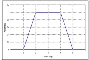
For loading, the effects of frequency and velocity has been investigated and the results showed that loading frequency effects on pavement strain in comparison with the effect of loading velocity is relatively smaller. Zoghloul and White [12] studied the dynamic responses of flexible pavements and observed close matches between the results of ABAQUS and the local measurements. In this research, three different velocities are considered to simulate tire movement. For this to be done in finite element model, load amplitude variations versus defined time is shown in Figure 1. Trapezoidal impact loading has been applied to the first part and then transferred to the next part. For each part, the same patterns are operated on each part [11]. The loading cycle was used for the analysis which time values of T1 to T5 are the functions of the vehicle speed [12].
Pasquini et al. [13] carried out a real-scale field trial, Falling Weight Deflectometer (FWD) measurements and interface shear tests in order to evaluate the effect of use of geogrid in improvement and consolidation of asphalt roads. The results demonstrated better and more appropriate pavement performance in the bearing capacity increment utilizing reinforcement. Nair et al. [14] performed laboratory studies on granular sub-base materials reinforced with multiple layers of geogrid with triaxial experiments under static and dynamic loadings. It is observed that reinforced materials bear more stresses than unreinforced materials at the same strain level and the beneficial effects of reinforcement increase with increase in the quantity of reinforcements.
3. RESEARCH METHODOLOGY
In this research, the longitudinal tensile strain of asphalt layer bottom under different velocities and loadings was compared with Pennsylvania field results and satisfying conformity among the results was obtained. Ensuring the model and the interface of layers conditions, a geogrid layer was established in different depths and the effect of several parameters on pavement response was investigated.
The modeling results related to the base thickness were compatible with the results of Al-Qadi’s experiments [2]. Then, the effect of different parameters including load, velocity, elasticity modulus and the thickness of the base layer on determining the optimal positioning of geogrid was investigated. The results demonstrated that elasticity modulus and the base layer thickness parameters were effective in this case.
4. VALIDATION
In order to ensure the model validity, the field test results were used. Sebaaly et al. [6] in 1993 presented a field experiment program covered under Federal Highway Administration. Installing gauges for measuring pavement strain under moving loads was included in this program. Two types of pavement sections, thick and thin, were considered for this study. The characteristics of thick pavement section are shown in Table 1. This empirical design for field test was focused on the longitudinal strains at the asphalt layer bottom under different velocities and loadings. Pavement material characteristics were estimated using FWD, illustrated in Table 1. In this field test, the applied load of semi-trailer was measured by Weight-In-Motion system (WIM). This load was considered in three load levels of empty, intermediate and fully loaded. For this experiment, the velocities of 32, 56 and 80 km/h were studied.
For dynamic analysis, each elastic layer behavior was taken into account. The elastic parameters are specified with elasticity modulus and Poisson's ratio. The characteristics of thick pavement section are indicated in Table 1.
5. NUMERICAL ANALYSIS
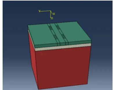
Regarding the available information and data, modeling is performed in the software and the results are compared with the field tests results. Three-dimensional model of the pavement structure in ABAQUS software is shown in Figure 2.
According to the elasto-dynamic theory, the governing equation of dynamic response for multilayer system can be written as follows:
u C u u t (1)
TABLE 1. Characteristics of pavement materials estimated by FWD
Pavement layers Thickness (m) Elasticity modulus (MPa)
Asphalt 0.254 2550
Base 0.254 207
Subgrade 3.81 152
Figure 2. Three-dimensional pavement model in ABAQUS
In Equation (1); u, u and u are displacement velocit and acceleration vectors related to the node, respectively; moreover, M, C and K are mass, damping and stiffness matrices, respectively. P(t) is the load matrix related to the pavement dynamic system.
Considering a small damping problem related to asphalt pavement, Rayliegh damping theory is used in this study. Damping matrix can be written as a linear combination of mass and stiffness matrices that is shown in Equation (2).
α β C{ (2)
Spectral damping scheme utilized in the dynamic analysis is Rayliegh damping. This model includes the damping matrix {C} shown in Equation (1). Considering both modes having the same damping ratio of ξ Ra liegh coefficient can be used; α and β values are empirically equal to 0.04 and 0.01, respectively [15].
5. 1. The Effect of Load and Velocity In this section, the effect of load and velocity parameters on pavement response is investigated and the numerical results are validated by Pennsylvania laboratory results. Moreover, the geogrid is modeled and the optimal positioning of geogrid is examined.
The asphalt layer bottom longitudinal strains are indicated in Table 1.
TABLE 2.Longitudinal tensile strain of asphalt layer bottom at different velocities and loads (micrometer per meter)
V el o ci ty (k m/ h ) A B A QU S (e mpt y tr a ile r) Pe n n . ( empt y tr a ile r) A B A QU S (i nter m edi a te lo a d ed tr a ile r) Pe n n . (in te rm ed ia t e lo a d ed tr a ile r) A B A QU S (f u lly lo a d ed tr a ile r) Pe n n . ( fu lly lo a d ed tr a ile r)
32 52.9 54 71.4 81 157.2 172
58 37.5 38 47.4 49 90 96
The graph of the asphalt layer bottom longitudinal strain vs. velocity is depicted in Figure 3.
The results indicate a satisfying conformity between the model and field test results. Also, there is a significant decrease in errors under small loads and high velocities. Since the tensile strain of asphalt layer bottom is reduced by velocity increment, the pavement service life could be extended by increasing the design speed.
In this modeling, three-dimensional solid and shell elements are used for modeling layers and the geogrid, respectively. Meshing model has been considered in a way to reach the best and the most accurate results. 8 nodes linear brick reduced integration elements (C3D8R) meshing has been used to improve convergence rate. C3D8R elements are of quadratic type. The quadratic elements present better results than the linear interpolation elements [16]. The 8-nodes brick element was used to generate the FE pavement model [17].
Also in order to model the interaction and relative displacement between the soil and the reinforcement it is necessary to include an interface element [18]. In this modeling, contact between the layers, is friction.
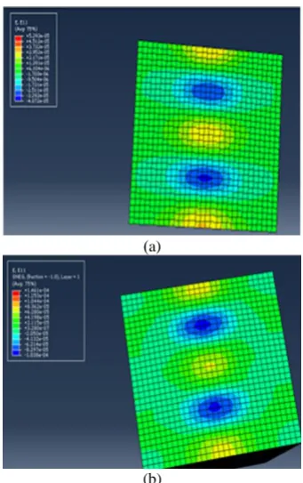
5. 2. Optimal Positioning For geogrid modeling, Abdessemed’s [16] studies were taken into account. Geogrid thickness is considered equal to 1 mm, Poisson's ratio equal to 0.3 and elasticity modulus is 630 MPa [15]. Figure 4 shows the results of numerical modeling using the ABAQUS software for two types of non-reinforced and reinforced pavement with geogrid.
In order to investigate the effect of several factors on geogrid position to obtain higher efficiency on pavement systems and more strain reduction, different parameters including layer thickness, layer elasticity modulus, load effects, Poisson's ratio and velocity variations were considered.
Figure 3. Longitudinal strain in different velocities
)a)
(b)
Figure 4. (a) The model without geogrid under 7.5 kN load and velocity of 20 km/h and (b) reinforced by geogrid at the asphalt layer bottom under 7.5 kN load and velocity of 20 km/h
TABLE 3. Tensile strains of asphalt with different reinforcement positions
Base layer
thickness (m) Sub-base
Middle of base layer
Upper one-third of the base layer
0.7 134.2 127.7 125.3
0.254 124.8 129.7 133.6
TABLE 4.Asphalt tensile strains with different reinforcement positioning
As
p
h
al
t layer
elas
ticit
y
m
od
u
lu
s
B
as
e
layer
elas
ticit
y
m
od
u
lu
s
F
or
re
in
for
ce
m
e
n
t
at
t
h
e
as
p
h
a
lt
layer
b
ot
tom
F
or
re
in
for
ce
m
e
n
t
at
t
h
e
b
as
e
layer
b
ot
tom
Chan
ge
s
E
las
ticit
y
m
od
u
lu
s
rat
io
R
at
io
of
st
rain
s
2550 107 163.9 139.1 15.13 23.8 1.178
2550 207 146.1 124.8 14.57 12.31 1.170
2550 507 110.1 101.7 7.63 5.02 1.082
Figure 5. Diagram of velocity versus longitudinal strain for different loadings and velocities
The results are shown in Tables 3 and 4. Although the changes in Poisson's ratio, velocity and load have no impact on the optimal position of reinforcements, parameters such as thickness and elasticity modulus were effective. Figure 5 illustrates the results of modeling for reinforcement positioning at the asphalt layer bottom and the base layer bottom.
The results indicate that using geogrid leads to the tensile strains reduction. The decrease of strain in greater loads and lower velocities is very explicit and the rate of these changes can be reduced by increasing velocity and decreasing vehicle weight. Indeed, it can be concluded that geogrid in greater strain levels demonstrates better results in improving the reinforcement resistance properties. Also, it can be inferred that for a flexible pavement, the optimal position for geogrid is in the base layer bottom. The modeling shows that different velocities and loads have no effect on optimizing the position of reinforcement.
Also, middle of the first layer, one-third of the base layer, middle of the base layer and two-third of the base layer were modeled. The results for fully loaded trailer with 32 km/h velocity are shown below. For the thicknesses less than 0.6 m, the lowest strain is related to the geogrid position at the base layer bottom while for the thickness equal to 0.7 m this value varies. The results of different modeling and outputs show that in the higher thickness of the base layer (about 2.5 times greater than asphalt thickness) the optimum position of geogrid is the upper one-third of the base layer.
Figure 6 shows the geometric shape of the model and software output for the maximum longitudinal tensile strain in 32 km/h establishing reinforcement at the height of upper one-third of the base layer.
The modeling results demonstrate that any changes in the base layer thickness can be effective on the optimal positioning of the reinforcement. Therefore, increasing the base layer thickness to 0.7 m, the optimal positioning of the reinforcement becomes at the upper one-third of the base layer. The other effective parameter is elasticity modulus of the base layer and its ratio to the asphalt elasticity modulus.
(a)
(b)
Figure 6. (a) Diagram of model and geogrid position at the height of the upper one-third of the base layer and (b) longitudinal strain at 32 km/h velocity with reinforcement placed at the height of the upper one-third of the base layer
The relevant results are indicated as followed. Asphalt tensile strains with different reinforcement positioning are indicated in Table 4. Also, diagram for the ratio of elasticity modulus versus ratio of strains is shown in Figure 7.
The model outcomes in ABAQUS software shows that increasing the elasticity modulus ratio of the asphalt to the base layer affects the optimal positioning of the reinforcement. Due to the geogrid impact, when the ratio of elasticity modulus of asphalt to the base layer is approximately equal to 4, the ratio of strains in these layers becomes equivalent. For higher values, the optimal position of the reinforcement is in the base layer bottom while for lower values it is likely to be at the asphalt layer bottom.
6. CONCLUSION
In this research, the finite element method using the software ABAQUS was utilized to determine pavement dynamic response. Step by step loading was used for modeling load movements. Validation of the model was performed via comprehensive study (Penn state test track) measuring the longitudinal strains of asphalt layer bottom. The results indicate a satisfying conformity between the computed strains from the model and field measured strains. Then, the role and optimal positioning of the reinforcement (geogrid) in asphalt pavements were investigated. Using the results of 50 models, a database for different parameters sensitivity analysis was created.
Since the tensile strain of asphalt layer bottom is decreased due to velocity increment, pavement service life could be extended increasing the design speed.
Geogrid has more impact on decreasing applied strains in lower velocities and higher loads. Actually, in greater strain levels, it demonstrates better results in improving reinforcement resistance characteristics.
Velocit oisson’s ratio and load parameters have no impact on optimal positioning of the reinforcement. The parameters of base layer thickness and the elasticity modulus ratio of layers are considered to be effective.
Using geogrid results in tensile strains reduction. For flexible pavement with low thickness of the base layer, the optimal positioning of geogrid is at the base layer bottom; and the upper one-third of the base layer for pavements with greater base layer thickness (2.5 times greater than asphalt layer thickness).
For the base layer with lower elasticity modulus, setting geogrid at the base layer bottom can be a convenient solution. Increasing the elasticity modulus of the asphalt to the base layer, the strains ratio variations are reduced. For the elasticity modulus ratio of approximately 4, the ratio of strains in these two layers become equivalent and decreasing this ratio, the reinforcement positioning at the asphalt layer bottom becomes of higher priority.
7. REFERENCES
1. Al-Qadi, I.L., Dessouky, S.H., Kwon, J. and Tutumluer, E., "Geogrid-reinforced low-volume flexible pavements: Pavement response and geogrid optimal location", Journal of Transportation Engineering, Vol. 138, No. 9, (2012), 1083-1090.
2. Al-Qadi, I., Dessouky, S., Kwon, J. and Tutumluer, E., "Geogrid
in flexible pavements: Validated mechanism", Transportation Research Record: Journal of the Transportation Research Board, No. 2045, (2008), 102-109.
3. Chen, D.-H., Zaman, M., Laguros, J. and Soltani, A., "Assessment of computer programs for analysis of flexible pavement structure", Transportation Research Record, No. 1482, (1995), 123-133.
4. Cho, Y.-H., McCullough, B. and Weissmann, J., "Considerations on finite-element method application in pavement structural analysis", Transportation Research Record: Journal of the Transportation Research Board, No. 1539, (1996), 96-101.
5. Kuo, C.-M., Hall, K.T. and Darter, M.I., "Three-dimensional finite element model for analysis of concrete pavement support", Transportation Research Record, No. 1505, (1995), 119-127.
6. Sebaaly, P., Tabatabaee, N., Kulakowski, B. and Scullion, T., "Instrumentation for flexible pavements—field performance of selected sensors", Federal Highway Administration, Washington, DC, (1991).
7. Huang, W.-C., "Improvement evaluation of subgrade layer under geogrid-reinforced aggregate layer by finite element method", International Journal of Civil Engineering, Vol. 12, No. 3, (2014), 204-215.
8. Mohamad, E.T., Latifi, N., Marto, A., Moradi, R. and Abad, S.V.A.N.K., "Effects of relative density on shear strength characteristics of sand-tire chips mixture", Electronic Journal of Geotechnical Engineering, Vol. 18, (2013), 623-632.
9. Ingold, T.S., "Geotextiles and geomembranes handbook, Elsevier, (2013).
10. Cox, B.R., McCartney, J.S., Wood, C.M. and Curry, B., "Performance evaluation of full-scale geosynthetic-reinforced flexible pavements using field cyclic plate load tests", in TRB 2010 Annual Meeting CD-ROM, Transportation Research Board, Washington, DC., (2010).
11. Hardy, M. and Cebon, D., "Response of continuous pavements to moving dynamic loads", Journal of Engineering Mechanics, Vol. 119, No. 9, (1993), 1762-1780.
12. Zaghloul, S.M. and White, T., "Use of a three-dimensional, dynamic finite element program for analysis of flexible pavement", (1993).
13. Pasquini, E., Bocci, M., Ferrotti, G. and Canestrari, F., "Laboratory characterisation and field validation of geogrid-reinforced asphalt pavements", Road Materials and Pavement Design, Vol. 14, No. 1, (2013), 17-35.
14. Nair, A.M. and Latha, G.M., "Large diameter triaxial tests on geosynthetic-reinforced granular subbases", Journal of Materials in Civil Engineering, Vol. 27, No. 4, (2014).
15. Rahman, M., Mahmud, K. and Ahsan, S., "Stress-strain characteristics of flexible pavement using finite element analysis", International Journal of Civil and Structural Engineering, Vol. 2, No. 1, (2011), 233-241.
16. Abdesssemed, M., Kenai, S. and Bali, A., "Experimental and numerical analysis of the behavior of an airport pavement reinforced by geogrids", Construction and Building Materials, Vol. 94, (2015), 547-554.
17. Chun, S., Kim, K., Greene, J. and Choubane, B., "Evaluation of interlayer bonding condition on structural response characteristics of asphalt pavement using finite element analysis and full-scale field tests", Construction and Building Materials, Vol. 96, (2015), 307-318.
Sensitivity Analysis of Road Actual Conditions to Evaluate the Optimal Positioning
of Geogrid Using Finite Elements and Dynamic Methods
G. Shafabakhsh, M. Motamedi
Civil Engineering Department, Semnan University, Semnan, Iran
P A P E R I N F O
Paper history:
Received 30 May 2016
Received in revised form 04 August 2016 Accepted 25 August 2016
Keywords:
Geogrids Flexible Pavements Finite Element Software Optimal Positioning Dynamic Responses
ديكچ ه
اَُار رز لًط رمع سیفم زًذ اب ٍیلقو لیاسي ريرم ي رًبع ضرعم رز اَراب
ي یاُتعرس تيافتم رارق سوریگیم . ،سیرگًئش
یارب اُشير هیرتُب زا یکی یزاسُب
اَُار ،سشابیم ٍك لیلسب ٍب هتذاسوا ریذات یبارذ
،اَ تلًُس ارجا ي ٍفرص ،یزاصتقا
زرًم ٍجًت رارق ٍتفرگ تسا . زا سعب ي لبق ،فلترم یاَ تعرس ي اَراب تحت یزاسير دساپ یبایزرا ٍعلاطم هیا زا فسَ
یزسع یاُیزاسلسم ،سشابیم سیرگًیش اب حیلست اب
مرو راسفا یاسجا زيسحم
(ABAQUS)
ترًص ،ٍتفرگ ناکم هیىچمَ
ٌسش یسررب سیو تيافتم یاُقمع رز سیرگًیش یریگرارق ایواًیسىپ یواسیم جیاتو زا ٍیليا لسم یجىس رابتعا یارب .تسا
رز ساسا تمارض ي ساسا ٍب تلافسآ ٍتیسیتسلاا ليسم تبسو اب سیرگًیش رارقتسا ،سَسیم ناشو جیاتو .تسا ٌسش ٌزافتسا لحم ساسا تمارص شیاسفا اب ي ٌزًب طابترا ٍتیُب
رارقتسا حلسم ٌسىىك ٍب ٍیلا کرتشم حطس زا کی
مًس یلااب ٍیلا ساسا
ٍك یماگىَ ي سىکیم رییغت تبسو
ليسم ٍتیسیتسلاا تلافسآ تبسو ٍب ساسا ازيسح ربارب 4 ،سشابیم يز هیا رز اُشورك تبسو
یارب .زًشیم ربارب ٍیلا ریزاقم
رتشیب هیرتُب ناکم رارقتسا حلسم ٌسىىك ساسا ریز ي یارب ریزاقم رتمك هیرتُب ناکم ریز ٍیلا
تلافسآ سشابیم . .سوزًب ریثات یب دساپ هیا رز خرچ نزي ي تعرس یاَرتماراپ