THERMAL ANALYSIS OF SHELL-SIDE FLOW
OF SHELL-AND TUBE HEAT EXCHANGER USING
EXPERIMENTAL AND THEORETICALMETHODS
S. Noie Baghban, M. Moghiman and E. Salehi
Department of Chemical Engineering, Ferdowsi University of Mashhad Mashhad, Iran
(Received: October 1, 1998 - Accepted in Revised Form: June 3, 1999)
In this paper the thermal behavior of the shell-side flow of a shell-and-tufe heat
Abstract
exchanger has been studied using theoretical and experimental methods. The experimental method Provided the effect of the major parameters of the shell-side flow on thermal energy exchange. In the numerical method, besides the effect of the major paramerers, the effect of different geometric parameters and Re on thermal energy exchange in shell-side flow has been considered. Numerical analysis for six baffle spacings namely 0.20, 0.25, 0.33, 0.50, 0.66, and 1.0 of inside diameter of the shell and five baffle cuts namely 16%, 20%, 25%, 34%, and 46% of baffle diameter, have been carried out. In earlier numerical analyses, the repetition of an identical geometrical module of exchanger as a calculation domain has been studied. While in this work, as a new approach in current numerical analysis, the entire geometry of shell-and-tube heat exchanger including entrance and exit regions as a calculation domain has been chosen. The results show that the flow and heat profiles vary alternatively between baffles. A shell-and-tube heat exchanger of gas-liquid chemical reactor system has been used in the experimental method. Comparison of the numerical results show good agreement with experimental results of this research and other published experimental results over a wide rang of Reynolds numbers (1,000-1,000,000).
Heat Exchanger, Shell-Side Flow, Baffle Cut, Baffle Space.
Key Words
ºB´{°n pA ²jB TwA BM ³§±§ ° ³Tw±Q »UnAoe ¤kL« ð½ ³Tw±Q ¬°nj ¬B½o] »UnAoe nBT n ³§B « ½A nj
²k¼ña
Baffle Space:¬Ajo¢MC ¨B£ S§Be y{ ºAoM ºjkî ¥¼¦dU /SwA ³T o£ nAo ³í§B « ° »wnoM jn±« ºjkî ° »Mo\U Baffle Cut (bc)= 0.16- 0.20- 0.25- 0.34:¬Ajo¢MC »£k½oM S§Be [®Q ° (bs) = 0.20-0.25-0.33-0.50-0.66/k¯A²k{ ³v½B « ©µ BM 1000000 BU 1000 pA ¦Th« pk§±®½njAkîA ºAoM ºjkî ° »Mo\U [½BT¯ ° ³T o£ ¨B\¯A -0.46 ¬A±®î ³M ,¬B½o] º±¢§A oM »]°oi ° ºj°n° B®« RAoYA T o£ o ¯ nj ° ³Tw±Q ¥iAj ¬B½o] ¥«B »wnoM ºAoM ºjkî x°n ³LwBd« ²p±e ¬A±®î ³M ºA³¯A±TwA ¤kL« »ñ½q¼ ²p±e ¨BªU ºjkî ¨±wo« ºB´{°n nj k½k] nB ð½ ³ªza ° S oe nAk « ³§jBí« nj ©T®«±« ²Ba Rn±æ ³M ¤kL« ºBµ³§±§ »UnAoe ° » @Bñ æA RAoYA ° ²k{ JBhT¯A J°B®ÇU ²kÇ«C Swj ³ÇM [½BT¯ /SwA ²k{ ³T o£ o ¯ nj ,k¯nAj j±]° Bµ³§±§ ³ » B ¯ nj ºro¯A ³§jBí« nj »UnAoe nj ³ ³§±§ ° ³Tw±Q »UnAoe ¤kL« ð½ pA »Mo\U x°n nj /kµj»« ¬Bz¯ »M±i ³M An B´¯Ajo¢MC ¼M »UnAoe ° »¯B½o] ǽA »Mo\ÇU [½BT¯ BM ²k«C Swj ³M ºjkî [½BT¯ /SwA ²k{ ²jB TwA ,jnAj nAo é½B« Ç pB£ »½B¼ª¼{ n±T @An 4¥ñ¼w nj ³Ç kµj»Ç« ¬Bz¯ [½BT¯ /kµj»« ¬Bz¯ An »M±¦ « A±U ³ SwA ²k{ ³v½B « ¬Ao¢½j »Mo\U [½BT¯ ° yµ°sQ /k{BM»« ¬Ajo¢MC »£k½oM oYA pA oTª´« ¬Ajo¢MC ¨B£ oYA ³§±§ ° ³Tw±Q ºB´§kL« ¥iAj S oe ¤B T¯A k®½Ao
INTRODUCTION
She ll-and-t ube he at e xchange rs are use d in ma ny t he r ma l industrie s [1]. T he ir p rop e r de signs play a vital role in he at re covery and increase the efficiency of industrial cycles. The
severely affected by parameters such as baffle spacing, ba ffle cut, R e and P r of the fluid. I n a p p r o p r ia t e se le ct io n o f e a ch o f t h e a bo ve -me n t io n e d p a r a me t e r s ma y cr e a t e problems such as reduction of cross-sectional area, creation of wide vortex regions, reduction of heat transfer and increase of pressure drop. Tinke r [2] e xamine d more t han 75 case s of different geometric parameters. However, due t o p r o b l e m s p r e va il i n g i n l a b o r a t o r y experiments, he managed to analyze only a few limited case s of baffle spacing and baffle cut. Patankar and Spalding [3] carried out numerical analyses using three dimensional models with a pr osmat ic she ll for t wo baffle s on ly. Th e y mentioned that due to the problems existing at t h e t ime t h e y we r e u n a ble t o va r y baffle numbers or other variables. Other investigators [4,5,6] have based their work on the model with one or more baffles restricted by two flat plates on the top and bottom. They assumed that the primary inle t flow was always paralle l t o the plate. This assumption is in direct contrast with real flows in exchangers.
P r e vio u s wo r k s h a ve r e ve a l e d t h a t e xpe rime nt a l analyse s face t he pro ble m of m e a s u r e m e n t o f d e t a i l t h e r m a l a n d hydrodynamic condit ions of she ll-side flow Numerical analysis has been carried out only for a part of exchange r as a ge omet rical module with fully developed flow. In this way, the effect of inlet and outlet conditions do not appear in calculations [5,6]. while in the present research, the entire geometry of the shell-and-tube heat exchanger has been considered.
In this investigat ion the first experimental tests were conducted on a shell-and-tube heat exchanger. The experimental results have been used for validating numerical analysis. The shell-side heat transfer coefficient has been obtained
by varying R eynolds number of shell-side flow (changing the inlet flow rate ), and measuring inlet-outlet fluid temperatures. By comparing the the ore tical and expe riment al re sults, t he t h e o re t ica l mo de l use d in ca lcu lat io ns for prevailing exchanger conditions was validated. The influence of ot he r baffle case s on he at t r an sfe r r a t e h as be e n inve st iga t e d u sin g theoretical models.
GEOMETRICAL CHARACTERISTICS OF THE HEAT EXCHANGER
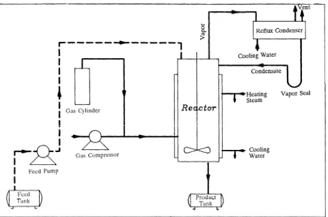
The he at exchanger use d in the experimental test was a part of a chemical reactor system [7]. The schematic diagram of the reactor system is shown in Figure 1. Thermal design of the heat exchanger was based on Kern's Method [8] and its mechanical design and construction on the TE MA standard [9]. The mat erial used in all parts of the heat exchanger was SS-316. It had four segmental baffles. All tubes were seamless. T h e r ig wa s e qu ip p e d wit h in st ru me n t s -Bourdon pressure gauge (accurate to
×
0.5 psi),Bourdon temperature gauge (accurate to
×
1K)a nd R o t a me t e r ( a ccu r a t e t o
×
0.5 lit ) fo r measuring temperature, pressure and flow rate -in different part s of t he he at exchanger. The e nd views of a t ube shee t and t he baffle are shown in F igures 2 and 3 re spe ct ive ly. O ther geometric characteristics of exchanger are as follows:N=121 IDs=0.86 m
t=0.01 m
L=1 m PT/ODt=1.5
A=7.6 m2
bc=25% ODt=0.02 m
q=130 kw
m=1 n=1
IDt=0.016 4m bs=0.195 m
THE GOVERNING EQUATIONS
These e quat ions writt en in cylindrical co-ordinates are as follows [10]:
a) The continuity equation:
__ (
Ã
b r
u) + __ __ (rb r
v)=0Ã
x1 r
Ã
Ã
rb) x-direction momentum equation:
__ [__ (
1
br
u2) + __ __ (rb r
v u)] = - ___ - __b
Ã
Ã
x 1 rÃ
Ã
rÃ
pÃ
rÃ
Ã
x (rbr
uv) - __ (Ã
rb
uu) + RxÃ
xc) r-direction momentum equation:
__ [__ (
1
br
uv) + __ __ (rb r
v2 )] = - ___ - __b
Ã
Ã
x 1 rÃ
Ã
rÃ
pÃ
rÃ
Ã
x (rbr
uv) - __ __ (r1b r
vv) - __r
ww + Rrr
Ã
Ã
x1 r
where
b
is the porosity defined as the ratio of the volume occupied by the fluid t o the total ( n omin a l) va lu e . Rx an d Rv ar e frict ion a l resistance of tube to flow which are expressed as:Rx= -2fx
r
u G/ (r
Dh) where:fx = 0.048 (G Dh/
m
)-0.2Rr = 2fr Gmax G/ (
r
PT) where:fr = [0.23 + 0.11/ (
¡
3PT/ODt)1.08] (G OD t/m)-0.15d) The energy equation:
__ [__ (
1
br
uh) + __ __ (rb r
vh)]b
Ã
Ã
x 1 rÃ
Ã
r= __ (
Ã
G
hb
___ ) + __ __ (rb G
h ___) + ShÃ
xÃ
hÃ
x 1 rÃ
Ã
rÃ
hÃ
rwhere Shis t he rat e of he at t ransfe r pe r unit vo lu m e o f t h e sh e ll flu id a n d h a s t o be calculated from experimental data.
The effect of the presence of the tube in the shell-side flow is included in two different ways. The first effect of the tubes is that they provide
distributed resistance to flow, thus producing a distributed "sink" for mome ntum. The second effect is that they produce source of heat. These effects of tubes are introduced into calculations th ro ugh t he mome nt um a nd e ne rgy in t he above equations.
e) The equation of turbulent kinetic energy (k) and its dissipation rate (
e
):In vie w of t he disabilit y of t he k-
e
mode l t o co p e wit h a n iso t r o p ic flo ws [11,12], t h e t u r bu le n t st r e sse s a r e o bt a in e d fr o m a n alge braic stress mode l [13]. In t his mode l in addit ion t o t he six alge br aic re lat ions it is necessary to solve the equation for transport of kinetic energy of turbulence and its dissipation rate.__ [__ (r
1
r
uk) + __ (rr
vk)] = __ [__ (r__ ___)b
Ã
Ã
xÃ
Ã
r 1 rÃ
Ã
rG
ks
kÃ
kÃ
r + __[__ ___] + GÃ
k -re
Ã
xG
ks
kÃ
kÃ
x__ [__ (r1
r
ue
) + __ (rr
ve
)] = __ __ [r__ ___]G
Ã
Ã
xÃ
Ã
r 1 rÃ
Ã
rG
es
eÃe
Ã
r+ __ [__ ___] + C
Ã
1__ Gk - C2r
__Ã
xG
es
eÃe
Ã
xe
ke
2 k where:s
k=1s
e=1.3 [14] C2= 1.92C1= 1.44
NUMERICAL SOLUTION AND BOUNDARY CONDITIONS
Figure 4.Calculation domain.
The resulting algebraic equations can be given in the following common form:
i=N,S,E,W i=N,S,E,W
õ
(Ai - Sp)f
p =õ
Aif
i + Suwhe re
f
re pre se nt s t he ge ne ra l de pe nde nt variable , t he A' s are the coe fficie nts which contain contributions from the convective and diffusive fluxe s, Suand Spf
are the line arised so u r ce t e r ms. P o we r la w sch e me is u se d tocalculate the diffusion and convection terms. The set of simultaneous algebraic equations are solved by a semi-implicit it erat ive t echnique [15]. Be ca use o f t he e llip t ic n at u re of t he conservation equations, a complete description of the flow fie ld considered necessitate s the spe cifica t ion of bounda ry condit ions a t all b o u n d a r ie s o f t h e d o m a in o f in t e r e st . T h e bo u n d a r y co n dit io n s a t t h e in le t a r e specifie d once for all. At t he e xit plane t he con dit io n s a r e kno w be for e ha nd a nd it is assumed t hat t he radial gradients of all the variable s vanish on this plane. In t he re gions near solid boundaries, where the variations in the dependent variables may be very sharp, the outer solutions are matched by well-established wall functions [14].The specific wall functions employed in this study are:
(__)
r
t
w= unw(knwCm1/2)1/2[__ ln (E _______ ynw)]1 x
knwCm1/2
v
e
nw= (knwCm1/2)3/2 / xy nwwhe re
t
is t he she ar stress at the wall, unw, knw ande
nware ve locit y, t urbule nce e nergy and disspation rate at a normal distance ynwfrom the wall, x, E and Cm are constants which are given the values, 0.4187, 9.793 and 0.09 respectively. The subscripts w and nw de note t he locations on and near the wall.The friction and t he rmal e ffect s of t ube s have been taken into account as a momentum sink in the momentum equation and heat source in the energy equation.
EXPERIMENTAL RESULTS
After several tests, the temperatures and flow rates on inlet and outlet fluid were measured. Typical results are as follows:
I n le t t e mp e r a t u r e o f sa t u r a t e d st e a m in 418 K tubes
O ut le t t e mp e r at ur e of sa t u ra t e d liqu id in 418 K tubes
290 K Inlet temperature of water inside shell
302 K Outlet temperature of water inside shell
40lit/min Flow rate of water inside shell
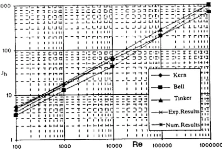
Figure 5.Heat transfer coefficient.
1,000,000). The small de viation be twee n t he curves are well within the range of experimental error, which is due to differences in the models used by different investigators.
THEORETICAL RESULTS
With regards to the satisfactory results
o bt a in e d fo r m t h e co mp a r iso n be t we e n t heore t ical and e xpe riment al re sult s on t he entire field of shell-side flow, in this section the role of baffles on the flow and the temperature profile have bee n invest igate d by numerical methods.
Temperature Profile in Exchanger without
Baffles
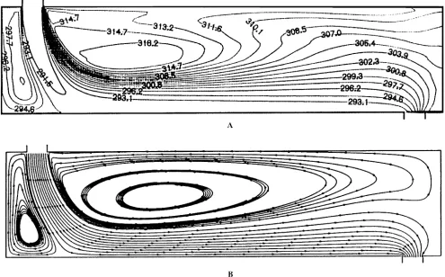
Initially, an exchanger without baffles was analyse d as a base condit ion. Figure 6-A shows streamlines inside the exchanger without baffle s. As can be obse rve d, a wide fie ld of vo r t e x flo w is ca u se d o n t h e t o p o f t h e exchanger. Figure 6-B shows the temperature profile inside the shell in the form of isothermal line s. It h as be e n obse rve d t hat due t o t he absence (disuse ) of baffles and consequent ly creation of wide vortex and trap of a large part of fluid inside the shell, the fluid temperature in this section increases considerably. H owever, the rest of t he flow inside the shell leaves the exchanger in a short path and parallel to tubeswit ho ut cau sin g conside rable t e mpe r at u re change. In other words, the e ntire exchanger has not be en uniformly used for opt imal heat exchange.
Temperature Profile in Exchanger with
Baffles
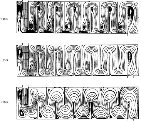
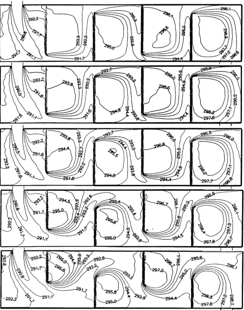
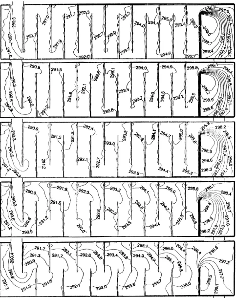
There is no exact se lect ion for baffle spacing and baffle cut for optimal conditions in practical situations. O nly baffle spacing in the range of 0.2 to 1.0 and baffle cut in the range of 15% to 50% have been indicated. Hence, in this re se arch, six baffle spacings (bs= 0.20, 0.25, 0.35, 0.50, 0.66, 1.0) and five baffle cuts (bc= 16%, 20%, 25% 34%, 46%) have been analysed numerically.Th e st re amline s for bs= 0.33 and t hr e e baffle cuts are shown in Figure 7. In this figure a wide vortex field observed in Figure 6-A has disap p e a re d an d t h e flow pa sse s a lon ge r distance. In other words, the entire volume of the exchanger has been properly uses and only in t h e co rn e rs an d be hind t he ba se o f t he baffles, small regions of vortex are detectable. In Figures 8 and 9 the isothermal lines for two baffle spacings and five baffle cuts are drawn. An analysis of these figures shows that:
In t he region with high vortex motion and a)
low t ranslation motion, the t e mpe rature increases locally and on the edge of baffles, considerable variations on temperatures are see n. In contrast to our expectations, the temperature does not increase rapidly at the inlet of the nozzle, but it appears in the last vortex region behind the last baffle.
At a constant bs, incre asing bc doe s not b)
cause considerable increase of temperature. By incre asing the numbe r of baffle s, t he c)
t e m p e r a t u r e o f flu id in side t h e sh e ll increases.
The temperature rise after the third baffles is d)
Figure 6. A- Stream line of exchanger without baffle and B- Isothermal lines of exchanger without baffle.
t he e xp e r ime nt al r e sult s a nd t h e ot he r numerical work [17].
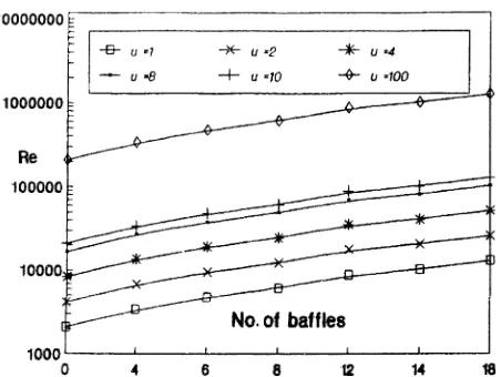
Effect of Baffles on Reynolds Number
By de finition, the R e ynolds numbe r inside t he sh e ll, acco rdin g t o t he followin g r e lat io n, depends on the number of baffles [18].a= _________IDs*C
Å
*bcPT G= __W
a Re= ____DhG
m
It can be see n that R e does not depend on t he pe rce nt age of baffle cut . The re fore , t o increase the heat transfer conefficient through c h a n gi n g R e yn o ld s n u m b e r , t h e m o s t appropriate solution is to increase the number of baffles. Figure 10 is a plot of the variation of R eynolds number versus the number of baffles for e n t ry ve locit ie s. It can o bse rve s t h at by in cr e a sing t he n umbe r o f ba ffle s t h e flow becomes t urbule nt more e asily and with less cost compared wit h increasing t he e nt rance
velocity.
Variation of Nusselt Number and Pressure
Drop
The variat ion of dimensionle ss Nusselt number versus baffle spacing for constant baffle cut is indicates in Figure 11. In this figure, it can be seen that with increasing baffle spacing the dime nsionle ss Nusse lt numbe r is de creased. Also in bc> 34% and bc< 0.45 the increase of dimensionle ss Nusse lt number is ve ry sharp. This phe no me non is the r e sult o f fie lds of vortex that appear between the repetitive lattice at the top and bottom.CONCLUSIONS
In the pre vious nume r ical a nalyse s [5,6], a repetition of an identical geometrical module of the exchanger has been studied as a domain of calculat ion. While in this research, as a ne w approach in current numerical analysis, entire ge ome t ry t o she ll-and-t ube he at e xchange r in clu din g e n t r an ce an d e xit re gion s we r e co n side r e d a s a d o ma in o f ca lcu la t io n . E xperimental and numerical results have been comp ar e d o ve r a wide r a n ge o f R e yn o lds
n u m b e r s ( 1,000 t o 1,000,0 00) . T h e mo st important results of this research are as follows: Using a combination of the experimental and 1.
nume rical me t hods, it would be possible t o st udy heat and flow rate in she ll-side even further.
C o mp a r iso n o f t e mp e r a t u re p r o file o f 2.
exchanger, with and without baffles, shows t ha t baffle s h ave t he vit al r o le in h e a t transfer rate.
The re su lt s also sho w t h at t h e e ffe ct of 3.
ch anging th e numbe r of ba ffle s is mo re
Figure 10. R eyno ld s n u m be r cu r ve fo r inlet co nsta nt velocity.
Figure 11.D imensionless Nu sselt nu mber for constant baffle cut.
Figure 12.Dimensionless Pressure drop for constant baffle cut.
important than varying the height of baffles for heat transfer rate inside the shell.
The temperature rise after the third baffles is 4.
periodic.
Incre asing R e ynolds numbe r in she ll-side 5.
cause s the incre ase of he at t ransfe r rate . Reynolds number can be increased by adding the number of baffles more easily and with less cost as compared to increasing the inlet velocity of the fluid.
I n cr e a sin g t h e dim e msio n le ss N u sse lt 6.
n u mbe r is ve r y sh ar p fo r bc> 34% a n d bs<0.45.
NOMENCLATURE
flow area across tube bundle [m2]
a baffles spacing [m] bs hydraulic diameter [m] Dh mass velocity [kg/s. m2]
G
heat transfer coefficient [W/m2.³C]
h
dimensionless heat transfer Jh
rube length [m]
L
total number in heat exchanger N tube length [m] ODt Prandtl number pr Reynolds number Re source terms S
shell-fluid radial velocity [m/s]
v
shell-fluid velocity [m/s]
r
dissipation of kinetic energy e
dependent variable f
heat exchanger area [m2]
A
clearance between tube [m]
CÅ
axial-flow friction factor fx
radial or circumferential mass flow rate [kg/s.m2]
Gmax
based on minimum free area tube pass
m
Pressure [kg/m2]
p
heat duty [W]
q
baffle cut baffle diameter [m]
radial-flow friction factor shell inside diameter [m]
tube inside diameter [m]
turbulence energy [m 2/s2]
shell pass tube pitch [m]
radial coordinate
distributes resistance of tubes in axial direction
shell-fluid axial velocity [m/s]
mass flow rate kg/m 3 ]
porosity (fluid volume/total volume)
REFERENCES
Butterworth, D. and Moscone, S. F., "Heat transfer 1.
heads into the 21st century", Chem. Eng. Prog., (Sep. 1991).
Tinker, T. , "Shell side characteristic of shell-and-tube 2.
heat exchangers", Parts I, II and III. General discussion of heat transfer, Proc. Instn. of Mech. Eng., London, (1951).
Patankar, S. V . and Spalding, D. B. , "A calculation 3.
procedure for the transient and steady-state behavior of shell and tube heat exchangers", IMPERIAL COLLEGE, (1972).
Patankar, S. V . and Spalding, D. B. , "A calculation 4.
procedure for heat and momentum transfer in three dimensional Parabolic flow", Int. J. Heat & Mass Transfer, Vol. 15, p. 1787, (1927).
Choi J. M. and Anand N. K., "Heat transfer in a 5.
serpentine channel with a series of right-angle turns",
Numerical Heat Transfer, part A, Vol. 23, pp. 189-210, (1993).
Kelkar K. M. and Patankar S. V . , "Numerical 6.
prediction of flow and heat transfer in a parallel plate channel with staggered fins", Journal of Heat Transfer, Vol. 109, (1987).
Noie Baghban, S. H. , "Design and construction of a 7.
chemical reactor under pressure with stirrer", Second Chemical Engineering Conference, Amirkabir Uni., Tehran pp. 84-89, (1996).
Kern, D. Q. , "Process heat transfer ", McGraw-Hill, 8.
(1950).
St a n d a r d o f T u b u la r E xch a n ge r M a n u fa ct u r e 9.
Association (TEMA), (1992).
Patankar, S. V . and Spalding, D. B., "Computer 10.
analysis of the three-dimensional flow and heat transfer in a steam generator", Forsch. Ing-wes, 44, (1978). Chen, Q., "Comparison of different k-e models for 11.
indoor air flow computations", Numerical Heat Transfer, Part B, 353-369, (1995).
Moghiman, M., "Numerical Predictions of the carbon 12.
burnout performance of coal-fired non-slagging cyclone combustors", Journal of the Institute of Energy, 69, pp. 31-38, (1996).
Rodi, W., "A new algebraic relation for calculating the 13.
Reynolds stresses", ZAMM 56, p. 219, (1976).
Launder, B. E. and Splading, D. B., "The numerical 14.
computation of turbulent flows",Computer Methods in Applied Mechanics and Engineering, 3, pp. 269-289, (1974).
Patankar, S. V . , "Numerical heat transfer and fluid 15.
flow", McGraw-Hill, (1980).
Bell, K. J., "Final report of the cooperative research 16.
program on shell and tube heat exchangers", University of Delaware Eng. Exp. Stat. Bulletin 5 (1963). Fukai, J. and Miyatake, O., "Laminar-flow heat transfer 17.
within parallel-plate channel with staggered baffles",
Heat transfer, Japanese research, 22 (2), (1993). Ludwig, Ernest E. "Applied design for chemical and 18.