Vol. 2 (2012) No. 3 ISSN: 2088-5334
Optimization of Circular Side Door Beam for Crashworthiness
Analysis
Raja Sharmi Raja Husin
1, Nur Liyana Tajul Lile
2, Sazali Yaacob
2 1 Mechanical Engineering Department, Polytechnic Sultan Abdul Halim Muadzam Shah06000 Jitra, Kedah E-mail : [email protected]
2School of Mechatronic Engineering, University Malaysia Perlis Kampus Ulu Pauh, Arau, Perlis
E-mail : [email protected]
Abstract— Structural optimization related to crashworthiness and energy absorption capability is particularly importance to the automotive industry. The optimization involves highly nonlinear computational analysis and design with many material and structure parameters. This paper presents a crashworthiness design of the circular side door beam which attach to the side door structures. The response surface method (RSM) is utilized to formulate the complex crashworthiness design problem in the case of optimization. In this study, side door beam will be optimized. The beams in circular shape were studied and compared. The focus is on finding an optimum cross-section shape of the beam in order to improve the energy absorption character. An optimization problem is formulated to find the maximum energy absorbed with the maximum peak load as a constraint, the shape of the beam cross section and the thickness as variable. The structure optimum design and simulation analysis of automobile side-door beam was carried out by using Finite Element (FE) method.
Keywords— Side door beam, crashworthiness, optimization, RSM.
I. INTRODUCTION
Crashworthiness design of vehicles for passive safety aims to obtain a strong, crushproof passenger surviving cell connected to several components able to absorb and dissipate energy in a stable and controlled manner. In the case of side impact collision, side door beam which is installed in the door played a very important role to absorb a lot of energy, thereby reducing the amount of energy transferred to the occupants. Investigation on crushing energy absorption, induced decelerations and consequent applied forces of this kind of structures has been carried out by many researchers. Several theoretical models have been developed and refined to predict the absorbed energy of side door beam [1], [2]. Numerical analyses and experimental validation have been carried out on the side structure and a door trim [3], [4]. However, few attempts have been made to optimize the crashworthiness of side door structure by applying structural optimization techniques [5], [6], [7].
Most research [3] – [7] related to the side door beam has been performed with the door assembly or the BIW (body-in-white) system on account of test regulations. That is, it is not easy to predict the effectiveness of the side door beam during the design process. In this research, the performance of a side door beam is predicted using only the door beam and not the BIW system. In considering the effect of the BIW system, an equivalent modelling is utilized. The optimization using response surface method (RSM) is used as a design approach to determine the thickness and the cross sectional shape of a side door beam. The objective is to maximize the energy absorption of a side door beam with respect to the mass density. The design variables are the thickness and the shape cross section.
II. PROBLEMMODELING
A thin-walled beam with the optimized cross-sectional dimensions should absorb as much crash energy as possible per unit weight, as explain by Hou [8]. This means, the specific energy absorption (SEA) should be set as an objective function and maximize during the optimum design. The SEA is defined as
SEA = Total energy absorb, Etotal / total structural weight. (1)
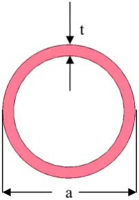
Two factors have to be considered in assigning constrains on this problem. The first one is human safety issues which is the maximum crushing force that occurs during the crash should be under certain criteria. It is very important in the automotive design and manufacturing. The other is the cross-section of thin-walled beam; the two design variables which are cross-section, a and the wall thickness, t (figure 1) should take values between their upper and lower bounds.
Fig. 1 Typical Circular side door beam cross-section
In this studies, only the beam cross-sections and the wall thickness has been consider in optimization. Thus, this optimization problems is modeled as
Maximize : SEA (a,t)
Constraints : Pm ≤ Criteria
aL≤ a ≤ aU and tL≤ t ≤ tU,
(2)
Where aL , aU , tL , tU are the lower and upper bounds of the design variables a and t, respectively.
III.RESPONSESURFACEMETHOD(RSM)[15] A surrogate model technique represented by the Response Surface Method (RSM) is one of the prevalent techniques to model highly-nonlinear systems beside a Genetic Algorithm (GA). As a non-gradient global method, GA demonstrates it capability of dealing with crashworthiness design problems. However, a problem of GA is relatively low computing efficiency. The ideas of surrogate model is to employ simple basic functions, typically the polynomial to approximate complex crashing response of a structure , which avoids the FE driven sensitivity analysis. In this context, Fang et al. [8] compare
difference basic functions on a fitting accuracy of the response functions. They suggested that the polynomial basic function generally provides a good approximation to model the energy absorption.
In this study, the response of the thin-walled circular side door beam is the SEA (a, t), which is approximate using the series of the basic function in a form of
Where n represents the number of basic functions Φ(a,t). In this paper, a polynomial is used to build up this basic function to formulate the SEA. In Eq. 3, βi, known as a regression coefficient, are estimated using the method of least squares. Suppose we have m(m>n) observations (obtains from FEA) for the yielded response yi (y1 – ym)
based on the m sampling design points (a,t)i, the least
squares function is therefore expressed as
Where the design points (a,t)i are selected from the specified
design space, εi is the error between the response yi observed
at these points. Afterward, the coefficient vector b= (β1, β2,…., βn) can be determine by δL/δβ = 0, which is,
b= (ΦTΦ)-1ΦTy, (5)
Where Φ denotes the matrix consisting of basic functions evaluated using m sampling points, which is
By substituting Eq. (5) into Eq. (3), the response surface (RS) model is created and the response function SEA (a,t) can be fully determined. The relative error (RE) between the observed response at those sampling points y(x) and the original response y (x) is
.
Other two important properties in evaluating the model’s accuracy are the sum of the residuals (SSE) and the total sum of squares (SST), which are
Where yi is the mean value of yi.
(3)
a
t
(4)(6)
(7)
(8)
The model fitness can be evaluated based on the F statistic, coefficient of multiple determinations R2, adjusted R2statistic and root means square error (RMSE) respectively, which are calculated as
According to the RSM theory, the larger value of R2 and R2
adj , and the smaller value or RMSE indicate the better fitness of RS model.
IV.PROBLEMMODELING
A. FE Model of Circular Side Door Beam
A beam structure considered in this study is circular shape with the hollow cut. The structure based on the Proton Wira which is manufacture in Malaysia as shown in figure 2. The side length a of the cross sections and the thickness t of the thin wall are chosen as design variables. The column length of L= 900mm remains as a constant in all design cases. The beam structures impact onto a pole with an initial velocity of 15m/s.
Fig. 2 Side door structure
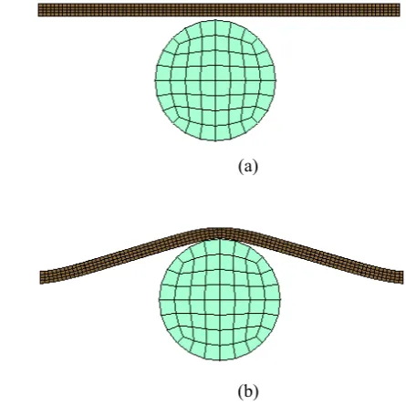
Figure 3 shows the schematic of the computational model. The structures are made of the aluminum alloy AA6061-T4 with the material properties of density, ρ = 2.7 × kg/m3, Young’s modulus, E = 70.0GPa, Poisson’s ratio v = 0.28, yielding stress, σy = 110.3MPa and tangent modulus, Et =450MPa.
(a)
(b)
Fig. 3: The schematic of the computational model, hexagonal thin-walled beam impacting the pole (a) 0 sec, (b) 0.01 sec
The plastic kinematic hardening material model with material type 3 in LS-DYNA is considered in the constitutive model. Since the aluminum is insensitive to the strain rate, this effect is neglected in the FE modeling [7]. The FE models, including the selection of elements, the definition of contact and the optimization process are the same for all these five different design cases except that the different cross-sectional layouts are used. Regarding the contact, nodes to surface contacts between the beam and a pole is defined, and meanwhile, a single surface contact algorithm provided by LS-DYNA3D is also utilized to consider the self-contact between the shell elements.
B. Sampling Design
In order to derive the response functions of SEA, a series of sampling points (based on t and a) are selected in a design space to provide sampling design for FEA. The design ranges are determined according to a previous research [8] and the optimization problem is defined as
Maximize : SEA (t,a) Constraint: Pm ≤ 90 kN,
30mm ≤ a ≤ 50 mm
and 1.0 mm ≤ t ≤ 3.0 mm (14)
In a design range of t and a, five level full factorial design is used for sampling, which resulted in 52 =25 design points evenly distributed within their design range. The FEA results for these 25 design points with difference values of t and a are used. The response functions of SEA are derived from the FEA results based on the 25 beam models.
C. Response Surface Model
RS model can be developed after having all the FEA results on 25 thin-walled beam models. The polynomials are used as a basic function in generating these RS models. In this section, linear, quadratic and cubic polynomials are used in order to validate the selection of design points and the orders (10)
(11)
(12)
(13)
of polynomial. The accuracies were evaluated by using following Eqs. (8)- (13). The regression coefficients βi for these polynomial are determined using Eqs. (5) and (6). The response polynomials function of SEA are :
Linear form
SEA(a,t) = 96.6604 + 0.1136a + 2.8834t
Quadratic form
SEA (a,t) = - 4.4457+6.0882a + 4.1656t – 0.0868a2 + 0.0523at – 0.779 t2
Cubic form
SEA(a,t) = - 61.4711 + 11.1033a + 5.7910t - 0.2272a2 - 0.1670at + 0.3843t2 + 0.0013a3 + 0.0024a2t + 0.0135t2a - 0.2724t3
The results of approximations are summarized in Table 1for the circular side door beam. the largest value of R2 and
R2adjand the smallers value RMSE goes to quadratic
polynomial. The table clearly show that of all these three Rs model, the quadratic polynomial function consistently provide the best approximation. The data also validate the factorial selection of the evenly distributed 25 design points in the entire design domain.
TABLE 1
ACCURACY OF DIFFERENT POLYNOMIAL RS MODELS FOR CIRCULAR SIDE DOOR BEAM
RS model R2 R2
adj RMSE
Linear polynomial 0.2541 0.9322 7.6599
Quadratic polynomial 0.9616 0.9899 0.4531
Cubic polynomial 0.9497 0.9698 0.7420
As a result of least square procedure, the quadratic response functions of maximum peak load, Pm is respectively given as
Pm (a,t) = 27.6594-0.8730 a – 9.9197t + 0.0163a2 + 1.05769at +2.6343 t2
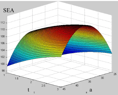
Fig. 4: Quadratic RSs of SEA for circular side door beam
Figure 4 shows the RSM result of quadratic polynomial for circular side door beam. The results of SEA increased with the increasing in the beam thickness. Besides that, the increments of SEA result in contra with the beam diameter.
Afterwards, the optimal design is obtained using constrained nonlinear multivariable optimization algorithm, which is a=30mm, t=2.34mmwith SEA of 109.25 kJ/kg and Pm of 90.00kN.
V. CONCLUSIONS
This paper presents the crashworthiness design of the circular side door beam which is attach to the side door structures. Response surface methods are used to optimize beam cross-section with respect to the maximum specific energy absorption and the maximum peak load as a constraint. Three different type of polynomials function of response surface model were used. The error evaluation shows that the quadratic polynomial is the best function in this study. By using an optimization algorittm, the optimum circular side door beam cross-sectional is 30 mm in diameter, and 2.34mm as a thickness.
ACKNOWLEDGMENT
I would like to thank my supervisor, Pn Nur Liyana Tajul Lile, Prof sazali Yaacob and Dr Rakhmad Arief Siregar, lecturer University Malaysia Perlis. And less but not least, my lab mate, Humairah Mansor and Hilman Akil for their help during my study.
REFERENCES
[1] Wenguo Qi, X.L.Jin, x.Y. Zhang, “Improvement of Energy-Absorbing structures of a commercial vehicle for crashworthiness using finite element method”, Int J Adv Manuf Techol (2006) 30: 1001-1009 [2] Tso Liang Teng, Kuan Chun Chang, Chien Hsun Wu, “Development
and Validation of Side Impact Crash and Sled Testing Finite Element Models”, Vehicle System Dynamics, Vol. 45, No10, Oct 2007, 925-937
[3] B.D. Youn, K.K.Choi, R-J.Yang, L.Gu, “reliability-based design optimization for crashworthiness of vehicle side impact”, Struct Multidisc Optim 25, 1-12 (2003)
[4] H. Huh, J. H. Lim, J. H. Song, K.-S. Lee, Y.-W. Lee And S. S. Han, “Crashworthiness Assessment of Side Impact of an Auto-Body with 60trip Steel for Side Members”, International Journal of Automotive Technology, Vol. 4, No. 3, pp. 149−156 (2003)
[5] Brock Watson, Duane Cronin, brett Campbell, “Study of Vehicle Dynamics and Occupant Response in Side Impact Crash test”, University of waterloo, Canada, Paper Number 09-0016.
[6] Chin-Hsu Lin, “Modeling and Simulation of Van For Side Impact Sensing Tests”, General Motors R&D Center USA Paper Number 07-0060, USA
[7] Tso Liang Teng, Kuan Chun Chang, Chien Hsun Wu, “Development and Validation of Side Impact Crash and Sled Testing Finite Element Models”, Vehicle System Dynamics, Vol. 45, No10, Oct 2007, 925-937
[8] S.J.Hou, Q.Li, S.Y.Long, X.J. Yang W. Li, “Design Optimization of Regular Hexagonal Thin Walled Columns with crashworthiness criteria, Finite Elements Anal. Des. 43 (2007) 555-565.
[9] Kaushik Sinha, “reliability-based Multiobjective Optimization for Automotive Crashworthiness and Occupant Safety”, Struc Multidisc Opptim (2007) 33:255-268
[10] P.O.Marklund and L.Nilsson, “Optimization of a Car body Component Subjected to Side Impact”, Struct Multidisc Optim 21,383-292
[11] Byeng D. Youn, Kyung K. Choi, “Selecting Probabilistic Approaches for Reliability-based Design Optimization”, AIAA Journal, Vol.42, No.1, January2004
[12] Fabian Duddeck, “Multidisciplinary Optimization of Car Bodies”, Struct Multidisc Optim (2008) 35:375-389
[13] Bi, J., Fang, H., Wang, Q., & Ren, X. (2010). “Modeling and Optimization of Foam-filled thin-walled column for Crashworthiness Designs”, Journal of Finite Element in Analysis and Design, 46, 698-709. Science Direct.
[14] Liu, Y. (2008). “Optimum Design of Straight thin-walled Box Section Beams for Crashworthiness analysis”, Journal of Finite element in Analysis and Design, 44, 139-147.