Available Online at www.ijpret.com 205
INTERNATIONAL JOURNAL OF PURE AND
APPLIED RESEARCH IN ENGINEERING AND
TECHNOLOGY
A PATH FOR HORIZING YOUR INNOVATIVE WORK
INJECTION MOLDING METHODS DESIGN, ANALYSIS AND SIMULATION OF
PLASTIC CUP BY MOLD FLOW ANALYSIS
MANMIT SALUNKE1, RUSHIKESH KATE2, VISHWAS LOMATE3,
Assistant Professor, Department of Mechanical Engineering, J.S.P.M.’S B.I.T, Barshi, Solapur, Maharashtra, India
Accepted Date: 15/03/2016; Published Date: 01/05/2016
\
Abstract: Mold flow simulation helps designers to see how their designs will be resulted after injection molding process without needing to do the Injection Molding process. The use of simulation programs saves time and reduces the costs of the Molding system design. Injection molding design simulation holds an important role in analyzing the outcome of the design. In this paper plastic cup part is analyzed and studied to solve the problems frequent rejections due to as shrinkage, weld lines, air traps, and sink marks. All the designs were simulated with Autodesk Mold flow Adviser. Autodesk Simulation Mold flow effectively eliminates the use of trial and error method by validating and optimizing the design of plastic before production. This not only improves the quality but also help us to guide about the selection of machines and the production planning.
Keywords: Injection moulding, Mould design, Mold flow simulation, Optimization Plastic Injection mould, Mould Flow Plastic Advisor (MPA)
Corresponding Author: MR. MANMIT SALUNK
Access Online On:
www.ijpret.com
How to Cite This Article:
Manmit Salunke, IJPRET, 2016; Volume 4 (9): 205-213
Available Online at www.ijpret.com 206
INTRODUCTION
Injection Moulding is one of the common methods to do the mass-production of plastic product.Thermoplastics are science's gift to the toy industry. They can be melted at fairly low temperatures, molded in colors with fine detail, and stand up well to play wear because of their resilience.. Injection moulding is the most commonly used manufacturing process for the fabrication of plastic parts. A wide variety of products are manufactured using injection moulding, which vary greatly in their size, complexity, and application. Injection Molding is the way most of our plastic toys are created. The material is injected under pressure into a two-part mold. The material is allowed to cool, the mold is opened, and the solid product inside is ejected into a collection hopper. Common problems associated with injection molding are numerous.
2 .Computer Aided Simulation
Nowadays, Computer Aided Design is not limited to sketching and drafting, but also helps to create analysable models as needed for computer based process simulation. Mold flow software, used solution for Digital Prototyping, provides injection molding simulation tools for use on digital prototypes. Providing in-depth validation and optimization of plastic parts and associated injection molds, Moldflow software helps study the injection molding processes in use today. The Autodesk Simulation Moldflow results help to identify the main problem areas before the part is manufactured that are particularly difficult to predict with traditional methods. In conventional optimization process includes actual shop floor trials in which pattern, feeder size, shape and location cores, mould layout, gating etc are required to be changed in each iteration which is associated with machining cost, tooling cost, modification cost, melting cost, fettling and transportation cost as well as energy, materials, time are wasted in each trial until and unless the required results are obtained. Analysis is essential for designing and mould making through simulation step-up and result interpretation to show how changes to wall thickness, gate location, material and geometry affects manufacturability and also experiments with “what-if” scenarios before finalizing a design. Injection Moulding simulation software into the mould design process in order to analyze the product, foresee the possible defects, and optimize the design to achieve the maximum outcome of the products with minimum cycle time in each production cycle.
3.PROBLEM DEFINITION:
Available Online at www.ijpret.com 207 and then rework designs to avoid these problems. Create feed systems based on inputs for layout,size,and type of components, such as sprue, runners, and gates .
4. OBJECTIVES OF THE WORK
1.To analyze the behaviour of Thermoplastic material during the production cycle from the filling phase until the ejection phase .
2. To foresee the possible problem for a product design; and therefore able to op-timize the design in the mould design process .
3. To achieve the minimum production cycle time
4. To construct a rapid prototyping of the mould cavity design into a standard mould plate .
5.1 Model details
A 3d model of part toy is created in Mechanical Desktop
Fig5.1 a). CAD Model Of Plastic CUP
5.2 Process settings
Melt temperature: 240.0 (C) Mold temperature: 40.0 (C)
Injection locations: 1 Max. machine injection pressure: 180.000 (MPa)
5.3Mold Data
Mold material Aluminium A1
Available Online at www.ijpret.com 208
Mold plate dimensions A plate: 118 (mm) B plate: 168 (mm)
Fig5.3 a) mold
5.4Material Data
Family name-polyethylenes (PE)
Mold Temperature Range 20-60 °C
Melt Temperature 220°C
Ejection Temperature 80°C
Maximum Shear Stress 0.11 MPa
Maximum Shear Rate 400001/s
Modulus Of Elasticity 124 MPa
Poison Ratio 0.39
Shear Modulus 43.97 MPa
Melt Density 0.73537 g/cm3
Specific Heat 4230 J/Kg-C
Available Online at www.ijpret.com 209
6. Simulation Result
6.A Gate Location Analysis
Optimum gate locations may need to be examining by running the filling analysis on different best gate locations. Figureshows the result of gate location. Blue area represents the best gate locations for the part .
Fig. 6A ) best gate location
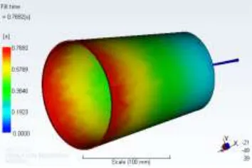
6.B Fill Time Analysis result
The Fill time result shows the position of the flow front at regular intervals as the cavity fills. At the start of injection, the result is dark blue, and the last places to fill are red. If the part is a short shot, the section which did not fill has no colour. Fill time is the time taken to fill up the part inside the cavity; it is also to show how the plastic material flows to fill the cavity.
Fig .6B)Fill Time Analysis result
Available Online at www.ijpret.com 210
Fig . 6C )Confidance of Fill Time Fig .6D) Quality prediction
6.E )Injection Pressure 6.F ) RESSURE DROP
Fig . 6E )Injection Pressure result fig . 6F) pressure drop result
6 .G TEMPERATURE AT FLOW FRONT 6 .H. Time To Reach Ejection Temperature
fig . 6G) temperature at flow front result Fig.6H) Time To reach ejection temp .
Available Online at www.ijpret.com 211
Fig. 6 .I )air trap analysis result fig. 6J) weld lines analysis resul
6 .L) cooling quality analysis result 6 .M). Wrap Analysis Result
Fig.6 L)cooling quality analysis result Fig.6M ) wrap analysis result
7. RESULTS AND DISCUSSION
Fill tab
Actual filling time 0.77 (s)
Actual Injection pressure 74.964 (MPa)
Clamp force area 44.1528 (cm^2)
Max. clamp force during filling 9.320 (tonne)
Velocity/pressure switch-over at % volume 97.78 (%)
Velocity/pressure switch-over at time 0.74 (s)
Estimated cycle time 13.06 (s)
Available Online at www.ijpret.com 212
Shot volume 21.8176 (cm^3)
Cavity volume 21.7426 (cm^3)
Runner system volume 0.0751 (cm^3)
Pack tab
Maximum clamp force during cycle 16.276 (tonne)
Max. wall shear stress 0.346 (MPa)
Total part weight 18.146 (g)
Cycle time 15.74 (s)
Cooling Quality
Maximum and minimum temperature variance 5.1 C & -1.2 C
Maximum and minimum cooling time variance 0.49 (s) & -0.57 (s)
Cool tab
Maximum temperature, part 49.2 (C)
Minimum temperature, part 32.6 (C)
Average temperature, part 41.1 (C)
Mold exterior temperature 27.4 (C)
8. CONCLUSION
Available Online at www.ijpret.com 213 later the gate position which shows the closest values to these parameters was taken into account and finally fixed as optimum gate position. For the mould maker and mould designer, the result of this study has shown how the Moldflow software has been able to assists to get the most optimum design out of a part product, and how to predict the future issue that might appear so it can either be solved if possible or find the alternative solution for it .
REFERENCE
1. Auto desk Mold-Flow Insight material data warehouse.
2. Manmit Salunke “Casting methods design, simulation and optimization of circular plate” 3rd International Conference on “Emerging Trends & Reasearch in Engineering “at Amaravati M.S. in I.J.P.A.E.T.(ISSN:2319-507X)
3. 3.Manmit Salunke “Injection molding methods design, optimization, Simulation of plastic toy building block by mold Flow analysis” International Journal of Mechanical Engineering and Technology, ISSN 0976 – 6340 (Print) ISSN 0976 – 6359 (Online)Volume 6, Issue 6, June (2015), pp. 33-41 Article ID: 30120150606004
4. Wikimedia Foundation, Inc, 2010. InjectionMoulding. [online] Available at: <http://en.wikipedia.org/wiki/Injection_moulding> [Accessed 28 August 2010]
5. Bryce, D. M., ‘Plastic injection molding: Manufacturing process fundamental’. Society of Manufacturing Engineers, (1996)
6. Moldflow Plastic Insight, 2014. Moldflow Tutorial. [Software tutorial] Mold-flow Corporation 7. Tang, S.H., Kong, Y.M.,Sapuan, S.M., Samin, R., and Sulaiman, S., “Design and thermal analysis of plastic injection mold” , Journal of Materials Processing Technology, Vol. 171, pp. 259-267, 2006.
8. http://www.engineersedge.com/injection_molding,.htm, 2006