100
Available online at www.ijiere.com
International Journal of Innovative and Emerging
Research in Engineering
e-ISSN: 2394 - 3343 p-ISSN: 2394 - 5494
DEVELOP INPROCESS CONTROL SYSTEM FOR
IMPROVING QUALITY FOR GRINDING AND HONING
MACHINES
Priyanka Wania
1
a, Mamta Sharma
2
aaUndergraduate1, Savitribai Phule Pune University, Pune, India bUndergraduate2, Savitribai Phule Pune University, Pune, India
ABSTRACT:
The grinding and honing machines deal with primitive processes required for manufacturing of ball bearings to avoid friction. The complexities that machines deal with is simply incessant, but yet, for proper manufacturing of the products from the basic steps, it is required that each and every minimal step is monitored and fulsome approach is given so as to avoid the probable errors and deliver an efficient product in the end. This paper thus deals with the various core process control systems that need to be designed interior to these high end machinery, to constrict the probable errors if any.
Keywords: PLC, grinding machines, honing machines, in – process control system for manufacturing high end machineries etc.
I. INTRODUCTION
The implementation of the complete manufacturing process of the product highly depends on the various grinding and honing machines which are ultimately used to produce ball bearings. Hence, it becomes very important to monitor each and every aspect at every step of manufacturing so as to detect and eliminate probable errors. Most of grinding operation quality is affected because of grinding spindle speed, work head spindle speed, clamping pressure etc .By monitoring speed during auto cycle following activity is to be done for quality improvement. Thus we are further using the 8 basic qualities such as ring rotation, work head supervision, oscillation supervision, HMS, interlocks, energy conservation, pressure switch interlock and cycle time reduction in the machines like SGB, SHG, FBM, SSB, FTC. To achieve these goals one possible solution is to implement the current system using PLC’s which would make the current system.
A. PLC:
Programmable Logic Controller is a digital computer used for the automaton of electromechanical process, such as control of machinery on factory lines. These PLCs were programmed which strongly resembled a schematic diagram of relay logic in ladder logic. A formal PLC definition comes from the National Manufactures Association.[4]
B. GRINDING:
Grinding is process used to improve surface finish, abrade hard materials, and to improve the tolerance level on flat and cylindrical surfaces by removing a small amount of material. For material removal; method used in grinding is called abrasion.[7]
C. HONING:
Honing is an abrasive machining process that produces a precision surface on a metal work piece by scrubbing an abrasive stone against it along a controlled path. Honing is primarily used to improve the geometric form of a surface, but may also improve the surface texture.[7]
Thus, PLC is the heart and soul while designing this complete process. These are the basic terminologies that we need to be acquainted with before starting to contemplate the various processes that need to be implemented in order to reprisal and extort efficient manufacturing. In the next section, thus we will discuss in detail about PLC.
II. PROGRAMMABLE LOGIC CONTROLLER
Programmable Logic Controller, in short PLC, is an electronic advancement of a digital computer used for industrial processes and automation, for instance used on factory assembly lines in order to control machinery. PLC is used for various inputs and output arrangements, to provide immunity against electrical noise, and limit extended temperature ranges and avoid resistance to vibration and impact. Programs which are used to control machine operation are stored in non-volatile memory. Automation is basically the delegation of human control functions to technical equipment towards achieving:[4]
Efficient usage of raw material and energy.
101
Higher productivity.
Superior quality of final product.
A. MMI GOT Series:
MMI which stands for Man Machine interfaces are basically panels which are mounted devices that provides efficient communication between the machine and operator. The keys and displays can be programmed. MMI allows easy operation and safe monitoring in the area of production. MMIs are used to display fault and operational messages which enable parameters specific to machine to be monitored and modified in suitable formats. The operator is always fully informed of the current status of operations by it.GOT1000 MMI can be directly connected to the MITSUBHISHI PLC via serial interface. It enables easy and quick installation. MMI also replaces the traditional push button panel. A series of touch screen terminals for efficient communication between operators with machine has been introduced by Mitsubishi.[4][10]
B. DIGITAL INUTS & DIGITAL OUTPUTS:
There are several digital inputs and outputs from float sensors, push button, and inductive proximity switch selector switch. Output unit operate much is much the same as input units with the only exception that the unit is either sinking which is supplying a ground or sourcing which is providing a voltage, discrete voltages or sourcing analog voltage or current. [11][10][4]
C. SERVO MOTOR
A Servo motor is a specialized type of motor which is automatically operated up to a certain limit which acts for a given command. It does this with the help of error sensing feedback mechanism. It is basically used to correct performance of the motor. The prime reason behind using this motor is that it provides an angular precision which means, it will only rotate as much as we want and then stop to wait for next signal to take further step. This is in contrast to a normal electric motor which starts rotating as the power is applied and the rotation continues until the power is switched off. Control of the rotation of the motor cannot be accelerated but only speed of rotation can be controlled and can be turned on and off.[12][11]
D. SPECIFICATIONS OF PLC:
I/O’s can be expanded from 16 to 4096.
The PLC CPU cycle period instruction is up to 34 ns
There is 16 bit analog processing value.
Counters are high speed
It has integrated RAM which is up to 252 K
The programming capacity is 8 K steps
Number of I/O is 1024 points
Number of I/O device points is 2048
The basic instruction processing speed is 160 ns
Memory Capacity is 3 MB
102
Interfaces include RS 232 and RS 422
Power supply needed is 24 V DC
III. IMPLEMENTATION OF THE CONTROL SYSTEM
The main goal here is to lessen the probable errors and deliver an exigent range of products. In order to meet with these goals, each and every step involved in manufacturing needs to be properly monitored and pertained. This is carried out by the further steps in this section. The steps are compliance of PLC logic and hardware integration. The raw structure is firstly programmed using PLC programming language which is further extended to monitor specific process via interfaces. [4]Mitsubishi GX developer software is used for programming. The PLC ladder is used for revaluing and determining each and every component specified in the step. Ladder Logic is used to program PLC. In this, sequential control of a process is required. This logic is useful for simple but critical control systems. PLC became more sophisticated as it was in very complex automation systems. Often the ladder logic is used in conjunction with HMI program on a computer workstation. The algorithm cycle of the same is given below:
Fig. 2 - Algorithm Cycle
IV. METHODOLOGY
After dealing with the programming, the basic terminologies behind the working of the control system and the different steps that are imbibed within are to be given an overlook. The different steps that are included in this system are as follows ring rotation, work head supervision, oscillation supervision, HMS, interlocks, energy conservation, pressure switch interlock and cycle time reduction.
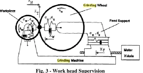
A. Work head Supervision:
Work head motor and ring are connected through belt, suppose the belt breaks this won’t be analyzed by the machine. There is a sensor placed on the spindle pulley. This sensor is placed so as to count the rotation. This sensor provides pulses according to the speed. At one end where the sensor is placed, suppose 500 is fed as the rotation count. Hence as per the efficiency, on the other end the same count needs to be obtained. Hence, to detect this, there is a sensor placed at the end. If the sensor on the other end goes low, this is detected by the sensor. When this is detected, machine stops automatically. This complete process of supervising the complete system is termed as work head supervision.
Fig. 3 - Work head Supervision B. Ring Rotation:
103 C. Oscillation Supervision:
Oscillation monitoring is essential for the honing process. Honing is an abrasive machining process that produces a precision surface on the metal work piece by scrubbing an abrasive stone against it along a controlled path. The geometric form of the surface is improvised by Honing, but it may also add up to the surface texture. Oscillation is the continuous variation in time domain, along the specified measure about a central value (often a point of equilibrium) or between two or more different states.
Thus, the oscillations of the oscillation spindle and the rpm of the work head spindle needs to be monitored for keeping a check on the complete ongoing process.
D. Interlock:
Grinding deals with constant friction between the abrasive materials. This results in constant wear and tear of the machine tools, and increase in the temperature. The increase in the temperature due to constant friction can hamper the entire system of operation. Hence, the system of interlocks deals with coolant safety and temperature safety.
During grinding, if the coolant is not properly available to the grinding machine, the wear and tear of the machine will increase with no control over the corresponding rise in temperature. Thus, cooling won’t be achieved efficiently and this will thus result in damage of the system.
To avoid this, interlock system, continuously monitors the temperature of the system and as per the need the coolant is continuously supplied to avoid the excessive abrasion caused due to continuous friction.
E. Pressure Interlock System:
As per the norms, the main purpose of interlock is to prevent initiating an in feeding process to the grinding wheel unless the grinding wheel slide is in a forward or operative position.
Both grinding & regulating wheels is equipped by pressure sensors. Using optional template, various types of from dressing can be obtained. a heavy duty grinding capability as well as high vibration dampening performance is provided by The hydrostatic Babbitt type spindle bearing is a 3 point support design and pressurized, filtered, recirculating oil system, eliminates metal-to-metal contact. A pressure switch interlock prevents spindle start-up until oil pressure is established. The spindle is stopped by the pressure interlock if the oil pressure fails, thus providing a longer spindle life. The machine base is made of casting, which is normalized and stress relieved, providing maximum rigidity to assure machine stability and vibration free operation. The hydraulic & lubrication system is air cooled to maintain constant oil temperature, which is also completely differentiated from the machine to eliminate vibration and dissipate heat.
F. Hourly Monitoring System:
HMS defines the hourly monitoring system of the machine. As per the operation of HMS, it monitors the number of rings that are produced as per the required time. The requirement of the rings produced depends on the value specified in the program. Thus the system on a regular basis monitors the rings produced. As per the requirement, there are changes made in the program so as to implement the same.
G. Cycle time reduction:
It is very important for the system to be flexible so that as per the need the rings are monitored. The program as per the requirement needs to be changed. For example, if 500 rings are need to be produced per 8 seconds, and as per the need this is to be reduced to 7 seconds; hence the program is modified and thus the rings are then produced. For Cycle time improvement locate idle time of machines and hence modified as per logic to improve cycle time.
H. Energy Conservation:
Energy conservation is the main deal of every electronic and automation manufacturing industries these days. With ever increasing rise of demands for products, the manufacturing terms and conditions of the company also need to be met. But as per the Government conditions and act, industries need to maintain certain setbacks and procedures so as to maintain and preserve the energy efficiency. Under this act and so as to maintain the integrity, SKF also takes certain procedures so as to conserve energy. There are many such procedures that the company deals with so as to conserve energy. But, we are being assigned the following energy conservation task:
It is not necessary for the complete system to be in operation all the time. There may be instances when the complete system remains idle. When the system remains idle, and the system is still ON; there is an unnecessary wastage of power supply. Hence, to avoid this and conserve energy efficiently, the system is programmed in such ways that if the system remains idle for a stipulated amount of time; the system is automatically shut down without supervision of any person.
V. CONCLUSION
104 1. Cycle time is reduced from a previous value to a new value.
2. Cost is reduced, as the PLC used is a highly reprogrammable device and is easy to maintain and troubleshoot when showing error.
3. Quality of the product is improved due to the inclusion of another grinding cycle and also the amount of bearings produced per hour has also improved, due to faster batch processing using PLC.
4. Reduction in Scrap formation.
5. Satisfactory results generated as per demands of the manufacturers.
ACKNOWLEDGEMENT
We would like to express our gratitude to Mrs.A.M.Ekbote our Guide, for her consistent guidance and inspiration throughout the project work, which we are sure, will go a long way in our life. We express our sincere thanks to Mr. A.B. Patil our Project Coordinator of department for his motivation. We owe sincere thanks towards Dr. N. B. Chopade, our Head of Electronics & Telecommunication Department, P.C.C.O.E, as all the success is the result of his affectionate encouragement. We are grateful to our Principal Dr. A. M. Fulambarkar for his encouragement and guidance throughout the engineering course. We are thankful to “SKF India Ltd. (Cubix Automation)” and Mr. Manish Adhav, our external Guide who gave us the sponsorship for this project. We express our sincere thanks to all our staff and colleagues who have helped us directly or indirectly in completing this project. Finally, we are grateful for the many useful comments and suggestions provided by reviewers, which have resulted significant improvements in project.
With sincere regards.
REFERENCES
[1] PLC TECHNOLOGY: Programmable Logic Control by Huge Jack.Mitsubishi_Q00_Q00UJ_Q01_QJ71 User Manual [2] PLC PROGRAMMING REFERENCE: Ladder diagram Programming Guide Book by Mitsubishi.
[3] Manual of Mitsubishi
[4] C D Johnson, “PLC Process Instrumentation and Technology”, 8th Edition, Tata McGraw Hill. [5] Parr, Industrial Control Handbook, Industrial Press Inc., 1999 ISBN 0-8311-3085-7
[6] M. A. Laughton, D. J. Warne (ed), Electrical Engineer's Reference book, 16th edition,Newnes, 2003 Chapter 16 Programmable Controller
[7] "The father of invention: Dick Morley looks back on the 40th anniversary of the PLC". Manufacturing Automation. 12 September 2008.
[8] Harms, Toni M. & Kinner, Russell H. P.E., Enhancing PLC Performance with Vision Systems. 18th Annual ESD/HMI International Programmable Controllers Conference Proceedings, 1989, p. 387-399.
[9] Maher, Michael J. Real-Time Control and Communications. 18th Annual ESD/SMI International Programmable Controllers Conference Proceedings, 1989, p. 431-436.
[10]Kinner, Russell H., P.E. Designing Programmable Controller Application Programs Using More than One Designer. 14th Annual International Programmable Controllers Conference Proceedings, 1985, p. 97-110.
[11]W. Bolton, Programmable Logic Controllers, Fifth Edition, Newnes, 2009 ISBN 978-1-85617-751-1, Chapter 1 [12]Keller, William L Jr. Grafcet, A Functional Chart for Sequential Processes, 14th Annual International Programmable
Controllers Conference Proceedings, 1984, p. 71-96.
[13]Gregory K. McMillan, Douglas M. Considine (ed), Process/Industrial Instruments and Controls Handbook Fifth Edition, McGraw-Hill, 1999 ISBN 0-07-012582-1 Section 3 Controllers
[14]Erickson, Kelvin T. (1996). "Programmable logic controllers". Institute of Electrical and Electronics Engineers. [15]Iqbal, S. (2008). "Programmable Logic Controllers (PLCs): Workhorse of Industrial Automation". 68-69. IEEEP
Journal: 27–31.