* Corresponding author. Tel: +98-21-82084238, E-mail address: [email protected] (S.Z. Shafaei).
Journal Homepage: ijmge.ut.ac.ir
R E V I E W P A P E R
-Recent developments in configuration design and optimization of
mineral separation circuits; A Review
Vahid Radmehr
a, Sied Ziaedin Shafaei
a, *, Mohammad Noaparast
a, Hadi Abdollahi
aaSchool of Mining, College of Engineering, University of Tehran, Tehran, Iran
ABSTRACT
The present research reviews two basic approaches for the separation circuit configuration analysis. The first approach is to optimize the circuit configuration. In this method, after a circuit modeling, a variety of search algorithms and mathematical optimization methods are used. Previous works show that this approach has more application in the flotation process. The second approach called the circuit analysis, evaluates the circuit configuration by considering a transfer function for each separation unit. This method provides great freedom for conducting a variety of investigations on the separation circuits.
Keywords : Circuit configuration; Circuit analysis; Optimization techniques
1.
Introduction
Mineral processing involves two basic steps: comminution and separation. In the comminution section, valuable minerals are liberated from gangue and at the separation stage, two products named concentrate and tailings are obtained. Various equipment is used for comminution and separation operations. In the comminution operations, the crushing and grinding equipment is used to change the feed size to achieve the appropriate degree of liberation of particles. In the separation section, however, the equipment of size classification and gravity concentration such as heavy media, magnetic separators,
flotation cells, and electrostatic separation is used [1]. The particle size
remains unchanged in the separation section, and only the feed flow is divided into two different concentrate and tailings based on the physical and chemical differences between the different feed particles. If the flotation process is to use the regrinding, then the particle size changes
[2]. The separation equipment divides the materials according to the
properties such as density, magnetic susceptibility, conductivity, and the properties of surface to other parts. For example, a gravity concentration plant can contain a number of jigs and spirals that divide the feed into
concentrate and tailings [3].
One of the most important issues in designing the separation circuits is how to connect the equipment to achieve the desired performance. In most cases, the arrangement of equipment in the processing circuits is based on a number of rules of the thump and industrial experience. So far today, in most cases, two conventional cleaner and
rougher-scavenger circuits are used for two-stage separations [4]. In these
circuits, the rougher stage is used to achieve maximum recovery. The concentrate from the rougher stage is sent to the cleaner stage for further concentration. The tailing of the rougher stage, however, is sent to the scavenger section to ensure the recovery of the most valuable rougher stage materials. As the number of stages and the complexity of the circuit increase, its evaluation only based on empirical rules becomes
very difficult, and sometimes impossible [5]. Also, considering that
there are different configurations for a separation circuit, finding the best combination through experiments is time-consuming and
expensive [6]. In such situations, it is necessary to use a mathematical
modeling and simulation for the evaluation of different circuit configurations. An optimal design of the separation circuits can eliminate the weaknesses associated with a single unit operation, while an improper design can lead to inefficient or even weaker circuits of
single units [7]. On the other hand, due to the fact that millions of tons
of ore are processed annually in the separation circuits, a slight improvement in the configuration of these circuits can have a significant
economic impact [8]. In the literature, a variety of evaluation methods,
and as a result, different circuit configurations have been proposed. Some only proposed counter-current circuits, in which just the number
of stages were different [4, 9-19]; some others have tried to find the best
configuration with circuit modeling and through the consideration of all possible layouts for a given feed and then the circuit optimization
[20-27]. In such cases, a variety of circuit configurations were proposed that, according to researchers, would increase the grade, recovery, separation efficiency, and/or the economic indicators.
Examining the separation circuits used in chemical engineering, their circuits are often counter-current and this is the number of steps, the type of equipment and process used, the design and operational parameters that make the difference and not unconventional circuit configurations. For example, counter-current circuits can be mentioned
for the distillation process [28]. However, it still seems difficult to
answer some of the following questions:
- Which circuit configuration(s) are more efficient for a given number of stages?
- Is there any configuration that always provides the best answer? - Until now, what comparisons have been made between the proposed configurations through the optimization methods with a counter-current circuit?
- Are the proposed configurations able to prove their efficiency in
Article History:
practice through the optimization methods?
As a result, the present study reviews a variety of methods for evaluating and optimizing the configuration of mineral separation circuits along with the advantages and disadvantages of each method. After presenting an introduction (Section 1), the involved concepts such as separation systems and their models (Section 2), and then the circuit configuration evaluation methods (Section 3) are presented. In this section, various types of optimization methods are reviewed. Also, a circuit analysis is considered as a method for evaluating the configuration of the separation circuits without the need for accurate information from the unit operations. Section 4 attempts to critically examine the advantages and disadvantages of previous works. Section 5 presents the conclusions.
2.
Concepts
2.1.Separation systems
A system can be defined as a group of objects that are interconnected in order to achieve a certain purpose within the framework of a
relationship or interdependent correlation [29]. The system can be an
arbitrary part of the whole process under consideration. In a mineral processing plant, grinding mill or flotation cell, part of a circuit or the entire processing plant can be a system. Materials or devices outside the system are the surroundings. The system is defined by drawing lines around that part of the process which is considered as the system boundary. To model the separation systems, understanding the concept of the system and the boundary of the system is essential. In mineral processing, in most cases, a single unit operation cannot achieve the desired quality (e.g., grade and recovery), and as a result, several devices
need to be used to achieve the required performance [7]. The
arrangement of the equipment in the separation section leads to the formation of separation systems or circuits. A separation system can be made of the same operational units, such as a flotation or a non-identical system, or a combination of the gravity, magnetic, and flotation equipment. Depending on the location of the unit operations, the inlet and outlet flows can be referred to as the feed, middling materials, or product streams. The layout design for separation circuits is often carried out based on past experiences as well as trial and error methods
[2]. In addition to creating the dependence on a designer's experience,
this approach can lead to inefficiencies in the separation circuits. As a result, the assessment of equipment configuration in the separation circuit is a way to properly understand and maximize the efficiency of separation processes.
2.2.Transfer function or mathematical model
A transfer function is a mathematical expression connecting the amount of a conserved quantity or component, j, entering to one step to
the amount leaving that stage at a steady state [13]. For the jth
component that leaves stage k and enters stage l, the conservation relation is written as follows:
jkl jkl jl
M = T M (1)
Tjkl = fraction of the conservation component, j, which leaves the kth
stage and enters stage l (transfer function).
Mjl = total amount of conserved quantity, j, which enters stage l.
Mjkl = amount of conserved quantity, j, which leaves kth stage and
enters stage l.
The transfer function or model is very simpler to the phenomenon under the investigation, but from the mathematical point of view, it may still be complicated. The complexity of mathematical models may make their application difficult; therefore, there is a great desire to use simple models. In other words, it tries to make the model as simple as possible, since even if its result is not correct, it can be modified with the smallest and simplest change. For example, the first-order kinetic model has long been used for the flotation process, while in theoretical research, more
complicated models are presented [30-37]. Another reason to keep a
model simple is that if a complex model does not lead to an answer, the
correction will be as complex as it would be. While modifying a simple model (even if possible) is as simple as the model. In the following, the types of transfer functions or models presented for separation equipment are investigated.
2-2-1. Empirical model
Curves that simply fit the shape of the recovery curves in a steady state are still widely used. These curves of the type of tromp do not attempt to establish logical relations or calculate mass transfer functions
[38]. For example, empirical models for heavy media devices are
provided by the modified Weibull function [39]:
a b
0 0
f(x) = 100(f + Cexp(-(x- x ) )
(2) In which:
f (x) = coal fraction to clean coal x = reduced specific gravity and
a, b, c and f0 are constant values.
The function f (x) is simply a good statistical fit to the washability data, as reflected in the correction coefficients. Other types of empirical models include trying to find the relationships between the response of a circuit, such as the recovery, and one or two other independent
variables such as collector and frother concentrations [40]. Although
these models are important, they do not have a theoretical basis. 2-2-2. Probability model
Probabilistic models suggest that the flotation process is a sequence of events that must occur prior to collecting particles. These models are based on theoretical considerations of flotation sub-processes events
and can describe the entire flotation recovery-time profile [41]. In this
approach, the particle recovery rate in flotation is associated with the
probability of floatation success, Px. For a specific size:
x c a
P = P P F
(3) In which:
Pc = probability of collision Pa = probability of attachment F = froth stability factor
All kinetic models in a steady state are reduced to probability type
models [42]. Also, according to [42], the bubble-particle collision zone
around the agitators are very important. Nowadays, new cells are more likely to be different than the agitators. It was assumed that if the recovery or probability of flotation in a single cell is equal to p, in a bank,
the values of p are equal in cells with probabilities of flotation p1, p2 to
pn. With this assumption, the bank recovery was proposed as follow:
n
R = R (1- (1- p) )
(4) In the case of flotation cells in plants, it is better to use cells of the same size and only different in terms of number in different stages of
the separation circuit (rougher, cleaner, scavenger, etc.) [19]. This can
provide the possibility of generating the identical p's. 2-2-3. Kinetic model
Currently, a variety of kinetic models is used. Given the mass flow rate of the input and output of a cell, the total mass balance of
component j for a single cell is as follows [40]:
j
j j j
dM (t)
= F (t) - T (t) - C (t)
dt (5)
In which: Fj(t) = feed rate
Tj(t) = tailing rate
Cj(t) = concentrate rate
Mj(t) = mass of j in the cell at time t
Equation 5 is the mass balance equation for a continuous flotation
cell. This equation is often expressed kinetically [16]:
j
n (t)
j j j
d(C(t) V(t)
= Q(t) Cf (t) - Q(t) Cj(t) - k (t) V(t) C (t)
where:
Cj(t) = concentration in the cell and tailings flow
Q(t) = volumetric flow of feed and tailing V(t) = cell volume
Cfj(t) = concentration in feed flow
kj(t) = constant flotation rate
nj(t) = kinetic order
Perfect mixing assumption was applied to equation 6. Equation (6) can be simplified for a single species in a laboratory flotation cell (Q(t)
= 0) with first-order kinetics (nj= 1) and constant chemical and
hydrodynamic environments in the cell [43]:
dc = - kc
dt (7)
By integrating:
0
R(t) = R (1- exp(- kt))
(8) Where in:
R(t) = floatable mass fraction after time t
R0 = floatable mass fraction at the infinity
Equation (6) at the steady state is simplified as follows [44]:
k R =
k+ Q/ V (9)
2.3.Circuit modeling
The optimization of the flotation circuit configuration is based on the modeling of the flotation process and its development for the circuit. For example, all possible combinations for a circuit with 2 cells/banks,
regardless of the physics of the flotation process, are shown in Figure 1
[45]. In this method, all possible connections between the flotation
banks are considered, in which S is a splitter. The idea of this approach
was initially proposed for heat exchanger systems [46] and then
proposed for the optimization of flotation circuits [45]. In Figure 1, F is
the feed entering the circuit, δFi is the contribution of the cell i to the
input to the circuit, βki, and δki are the mass proportion of the
concentrate and the tailings of the jth cell that enters the cell i. In these
flows, the subscript of zero means out of the circuit. A set of δFi, βki and
δki values, indicating a combination of the flotation circuit. For this
reason, this set of variables is called structural parameters of the circuit. If C(K), T(K) and MF(K) represent the flow rate of solids with kinetic constant K in concentrate, tailings, and feed, respectively,
( ) ( )
1 F
K
C K M K
K
(10)
1
( ) ( )
1 F
T K M K
K
(11)
In which, τ is the mean residence time in the flotation cell. A simple
mass balance, the total mass flow of j (for j=1,2, …, n) input into the ith
cell (for i=1,2, …, n) is given as follows:
, , , ,
1 1
m m
j i F j Fi j k ki j k ki
i i
F M T C
(12) If it is assumed that:
, 1 j i j i K
1 (13)
The mass flow rate of the component j from the ith cell to the
concentrate and tailing streams is as follows:
, ,(1 ,)
j i j i j i
C F (14)
, , ,
j i j i j i
T F
(15)
, , ,
,
1 j i j i j i
j i
C T
(16)
Replacing Cj,i of Equation 16 in Equation 12:
,
, , ,
,
m
j i
j i F j ki j k ki ki
k j i
F M T
1 1 (17) By replacing this term in Equation 15, we get the following relation:,
, , , , ,
,
m j i
j i F j Fi j i j i j k ki ki
k j i
T M T
1 1 (18) Equation 18 consists of a set of n×m linear algebra equations whichcan be numerically solved for several Tj,i values according to the
connection and design parameters. When the Tj,i values are known, we
can obtain the mass flow rate of the component j in the concentrate
stream of the ith cell using Equation 16. Now it is possible to calculate
the total recovery for the flotation circuit based on the structural parameters: , 0 1 1 , 1 N N
j i i i j c N F j j C R M
(19) , 0 1 1 , 0 1 1 m nj i i j i j
m n
j i i i j C w G C
(20)In which wj is the valuable mass fraction of the component j in the
concentrate stream (assumed to be the same for all cells). This problem is completed by the following constraints:
1 1 m Fi i
(21) 0 1 1 m ki k i
(22) 0 1 1 m ki k i
(23)0( , ) 1 (24)
,
0i j1 (25)
, 1
n
i i j i j
H T
(26) 100 1 d i i d V H d (27)
1 m i j V V
(28) In order to simplify the computations, the personal judgmentenforces the arbitrary constraint
on τi:0 i i 1, 2,...,m
To be acceptable, the concentrate grade must not be less than a
minimum level of G.
GG (29)
As a result, the problem is to find the best possible values of the decision variables, including the structural parameters and residence time in stages, to optimize the objective function such as recovery or grade. Different methods have been used to solve the optimization problem of the flotation circuit arrangement according to the objective function, the constraints, and decision variables. The following section examines these methods.
3.
Methods
basic approaches are reviewed. The first approach is to optimize the arrangement of separation circuits. In this approach, after modeling the circuit, various search methods are used to achieve the optimal circuit configuration. The second approach, called the circuit analysis, evaluates the circuit arrangement by considering a selection or transfer function for each unit operation. This method provides great freedom for conducting a variety of investigations on separation circuits.
Figure 1. All possible configurations, regardless of the process physics, for circuits with two cells/banks.
3.1.Flotation circuit configuration optimization
Most of the optimization methods have been applied to the flotation process. Three basic parameters in each optimization process include the objective function, decision variables, and constraints. Considering the wide range of these three parameters in flotation circuits, numerous studies have been conducted in this field. A variety of objective functions such as recovery, separation efficiency, profit, cost, and variety of decision variables such as the connection of banks, residence time, number of cells, kinetic constants, as well as different constraints such as minimum grade, mass balances, unwanted elements, and environmental issues are considered. Basic steps for the optimization of
the circuit configuration are shown in Figure 2. After modeling the
circuit, one of the search algorithms is used to find optimal values. Since most of previous studies for circuit configuration optimization have used mathematical programming strategies and genetic algorithms; first, these two approaches are reviewed and then other less-used methods will be reviewed.
Figure 2. Details of steps to optimize the configuration of the flotation circuits
[25].
3-1-1. Mathematical programming
To use a mathematical programming, the problem must first be converted into a mathematical model. To do this, we need an objective function for maximization or minimization. The mathematical model must also include decision variables affecting the objective functions and limiting constraints. By introducing a superstructure for all possible
flotation circuit configuration such as Figure 1, it can formulate a circuit
optimization problem in a mathematical programming approach. Depending on the mathematical model, one of the linear programming (LP), mixed integer nonlinear programming (MINLP) or mixed integer linear programming (MILP) can be used to solve the optimization
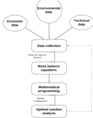
problem [6, 27, 47-50]. As shown in Figure 5, the steps to use the
mathematical programming approach are to collect data and define the objective function, the mass balance, and the application of the mathematical programming model.
The resulted configuration will be analyzed for the simplest and most feasible circuits. Initial studies on the application of mathematical programming with consideration of structural parameters and enrichment factor used for flotation circuit modeling and optimal layout
was obtained using linear programming [47]. Since the use of the
economic objective function leads to the creation of a variety of
nonlinearities in the circuit optimization problem [51, 52], the problem
of nonlinearity was decomposed to a number of problems and then
solved with MINLP [51]. In another study, two hierarchical
superstructures were developed to represent a flotation circuit [6, 27].
This breakdown of the optimization problem facilitated the linearization of the economic objective function using the Taylor series so that the conditions for using the MILP were provided to optimize the flotation circuit configuration. Through the use of MINLP and MILP, various layouts and equipment, such as banks with a different number of cells, regrind units, and flotation columns were considered in circuit layouts.
Figure 3. Optimization with mathematical programming [53]. 3-1-2. Genetic algorithm
A genetic algorithm is an effective search method in vast and large
spaces, which ultimately leads to the direction of finding an answer [54].
The use of GA to optimize the flotation circuit was initially proposed by
Guria et al. [55]. These studies used the first rating approach developed
by Mehrotra to model the flotation process [45]. GA was used to
evaluate the layout with a primary population containing all the circuit design for the problem. The authors improved the efficiency of the algorithm by jumping gene adaptation through multi-objective problem-solving. Guria and colleagues obtained optimal solutions superior to the traditional techniques by solving the problem of
optimization of two species, two cells, single objective [55]. The overall
recovery of the concentrate flowrate was optimized for a desired concentrate and a total constant volume of the cell. Decision variables were the connection parameters between cells and the average residence time. In the following, the optimization of single-objective and
multi-objective was used [56]. The functions objectives were: (1) maximizing
the recovery of the ore under optimization and (2) maximizing the valuable minerals (grade) in concentrate ore. A fixed total volume restriction of the flotation cell was also used. Since these goals are focused on contradiction, the non-dominated Pareto solutions were
1 2
b12
d10
b11
b22
b20
b10
b21
d11 d
12
d20
d21
d22
dF1 dF2
C1
C2
T1
T2
Feed
S
S S
S
S
Specify feed characteristics, circuit constraints and goals
Selecting one of the possible circuit configuration (a set of structural parameters)
Based on first order kinetics, flotation circuit modeling for selected configuration, then calculate the objective function that can be grade, recovery, separation efficiency, economic index or a combination of them.
For the first circuit, the calculations are stored as optimal case. For the next circuit, the value of the objective function is compared with the optimal circuit, and if the new circuit is better, it is stored as the optimal configuration.
If the stop condition is not met, then another set of structural parameters is selected and steps 2 to 5 are repeated. This step continues until the stop condition is achieved (finding optimal circuit configuration).
Steps for flotation circuit configurationatio n optimizationion
Environmental data
Technical data Economic
data
Data collection
Mass balance equations
Mathematical programming
Optimal solution analysis Define the objective
function
obtained. As a result, the designer can choose the right answer according to his experience. Fluorite flotation circuit was optimized using a
multi-objective genetic algorithm elitist [26]. The phenomenological model of
Mehrotra was used to model the plant in the absence of the regrinding
section [45]. For a specific arrangement of the circuit and a set of
operational data of the plant, the feed identification parameters were first determined using SGA-II. These parameters were then used to solve a two-objective optimization problem using NSGA-II-mJG to improve the plant efficiency. It was found that stream splitters in the proposed circuits could significantly improve the product recovery.
A genetic algorithm was used to simplify the circuit and optimize its
efficiency [25]. Entrainment was considered in addition to the first
order kinetics. The genetic algorithm was used for two optimization examples with the aim of achieving optimal concentrate grade for a given cell volume. Comparison of results with previous work showed that the proposed genetic algorithm significantly reduced the computational time for a two-stage flotation system, and a simpler circuit with similar efficiency was obtained. As the number of flotation stages increased, the number of circuit configuration increased significantly. It was found that many of the proposed layouts by GA were not logical due to the physical principles of the process and the experience of many years. Due to the random nature of the GA search, this limitation was not unexpected.
A robust GA with pulp and froth phase models was proposed to
describe a steady state flotation system [24]. This algorithm and
modeling system was used to produce the optimal flotation circuit for a given feed. The results showed that for three cells, the optimal circuit, the circuit with the highest profit from the combination of the grade and recovery, was a condition in which the cells were arranged in a row. For a circuit with 4 to 8 cells, adding cleaner cells resulted in higher incomes. In a recent study, a method for finding an optimal circuit arrangement
for a coal washing plant was presented [23]. The objective function was
to reach the highest mass recovery and at the same time produce a concentrate with a certain amount (11.2%) of ash. The input to the circuit was identified based on the size fractions and the corresponding rate constant. The results showed that, at a 95% confidence level, the difference between the modeled and measured values was 5.5 - 2.9% for mass recovery and 1.0-1.0% for the amount of the ash in the concentrate. When the proposed circuit configuration was implemented by GA at the plant, mass recovery from the initial value of 57.6% reached to 64.3%, while the amount of ash remained at an acceptable limit (10.9%). By adding one stage to the current three-stage circuit, it was predicted that mass recovery could increase by 3.8% while the quality of the concentrate was maintained in the desired range.
3-1-3. Other methods
Computational methods include direct and indirect search that have
been used for the optimization of the circuit configuration [45]. Indirect
search is trying to find local optimum by solving a set of nonlinear equations by assigning zero to the gradient of the objective function [57]. An optimal position can be found by limiting the search to zero gradient positions in all directions. Direct search methods (hill climbing) are local optimal search by following the objective function
in the direction related to the local gradient [58]. However, both
methods hunt only optimal points in the vicinity of the current situation, which depends on the initial guess in multiple optimal problems. As a result, there is no guarantee for global optimization, but local optimization can be used as a design guide. Enumerative method, search for any possible location in the search space (evaluates each possible
arrangement for circuit optimization) and is therefore, inefficient [54].
This method was used for small-scale searches and guaranteed optimal
global circuit design with an economic objective function [52, 59]. This
method is limited to solving small problems. In two separate studies, a method for optimizing flotation circuits was introduced using the
principles used in distillation columns [12, 60]. The author introduced
a new structure for non-homogeneous flotation modeling based on the concept of enrichment functions. This function can be compared with the principles of flotation modeling, although the rate constant and residence time are not directly considered. In this method, the recovery
relations are similar to those of the chemical equilibrium based on the concentration. In the case of flotation, the concentration of mineral in the concentrate is shown as a function of feed concentration and mass recovery, which can be related to operational parameters, such as air flow for the amount of chemicals used. By evaluating the partial derivation of the enrichment function, an optimal analysis for the counter-current flotation system is obtained. McCabe Thiele Staircase Diagrams are used to interpret the optimization results.
3.2.Circuit analysis
Circuit analysis was introduced by Meloy in 1983 as a general technique for assessing the effect of different configurations of unit
operations in the mineral processing and coal washing circuits [18]. The
principles of circuit analysis were used to evaluate the dynamic models
of flotation cells [16]. A dynamical model, lumped parameter for
continuous flotation circuits was developed to study the transient responses and frequencies of co-current and counter-current flotation banks. Although both circuits were sensitive to low-frequency sinusoidal inputs, and both were stable, co-current banks were oscillating require large first cell and longer residence time to reach the steady state. In the next study, the general equations of steady state were developed for
multi-feed separators with different transfer functions [15]. Using
circuit analysis algebra, these general equations were solved in a closed form and used to select the optimal points of unit operations in the circuit. The optimization of the heavy media coal washing circuit including roughers, cleaners, and scavengers was the next research title
in the circuit analysis series [61]. It was attempted to answer the
question as to whether multi-stage coal washing circuits could be optimized to improve the overall efficiency. The authors state that the rougher-cleaner-scavenger circuits are not common in coal washing, especially in gravity separation circuits. Their investigations showed that the best condition was obtained at low separation sharpness values. In addition, by increasing the scavenger density and decreasing the cleaner density, better conditions can be achieved. The circuit analysis method continued with two alternative approaches for designing the circuit layout. Both methods origin from a similar theory of the circuit analysis. However, efforts were made to reduce the difficulties of the circuit analysis. The first method is to accurately define the separation
functions in the circuit, namely rougher, scavenger, and cleaner [62].
According to their definition, a rougher is a unit whose feed is circuit feed, a cleaner is a unit that is fed by the concentrate flow, and a scavenger is being fed by tailings stream. In this study, the authors used the circuit analysis to represent four equivalent circuits, each of which represents a higher degree of detail consideration. The second circuit design approach defines three circuit design criteria: (1) the number of steps required; (2) the stage where the feed is introduced; and (3) the
flow pattern of the product [13, 63]. This approach begins with the
assumption of a generic cleaner of unspecified size, in which the concentrate is serially transfered to the next unit and the waste streams are returned to the previous point in the circuit so that the flow of the return stream is larger or is equal to the grade at the entry point, a law
initially proposed by Tagarat [64]. By constructing this general
structure, three design criteria can be solved algebraically on the condition that four design / operational parameters are identified: (1) a desired overall recovery, (2) the total ratio of the product to the tailings, (3) the ratio of the product to the waste that can be obtained per unit, and (4) the proportion of the feed component. These algebraic functions guide the initial design of the circuit because they naturally produce non-integers numbers. By rounding out and examining the different combinations of numbers, a design criterion that ends in desirable results can be determined. This configuration consists of valid designs that can be used in optimization and design process. In another study, with some changes, the circuit analysis method was used to find feasible
designs [65]. In this study, the weaknesses of previous works, such as
number of steps for the entire plant is first defined. The author assumed that each circuit had one rougher stage and an unspecified number of steps from scavenger and cleaner. The number of units in each stage is independently calculated by using the associated equation of tailings characteristics to the number of stages of the scavenger and the concentrate characteristics to the number of cleaner steps. Evaluation and correction of a gravity separation circuit were performed using
circuit analysis method [4]. Using the principles of circuit analysis, the
circuit configuration was simplified by reducing the number of spirals from 686 to 542. In addition, the new circuit was able to produce higher material grade at a higher recovery. In the original circuit, the materials were to be circulated 7 times in a 93% recovery to produce a certain grade. After the modification, the resulting circuit was able to achieve a desirable grade with one pass at the recovery of 94.74%. In other studies, the improvement of efficiency was achieved by implementing the
principles of circuit analysis for spiral separation of coal [10] and
column flotation [66]. Recently, a circuit analysis method has been used
to the sensitivity analysis of the circuit [67]. In this study, the sensitivity
analysis was introduced as a balance between experience and heuristic vision and numerical optimization strategies. Given that it is almost impossible to achieve global optimization through the experiment; a sensitivity analysis was used to determine the units with the highest sensitivity in the circuit. After identification of these units, empirical and laboratory analysis can be used to optimize or improve the efficiency of these units. Regarding the difficulties in circuit analysis calculations, a matrix-based algorithm was developed to obtain analytical and
numerical solutions for circuit [7]. The main advantage of this
technique is its numerical application that allows simple simulations in excel without performing iterative operations.
4.
Discussion
In this section, in addition to examining the questions raised in the introduction section, the advantages and disadvantages of the methods used in previous studies are also evaluated. In response to the question of whether there is a certain number of separation configuration(s) that is more efficient, it is better to consider the history of using mineral processing circuits. In the traditional perspective, separation circuits have been formed from two or three stages under the name of roughers, scavengers, cleaners, and other stages. Over the past years, the study of flowsheets used for various types of minerals including sulfide ore, coal,
and even industrial minerals [68] have shown that counter-current
separation circuit configuration can be used to process all kinds of minerals. It was found that for the separation of minerals, especially sulfide ores, usually 2 to 3 stages and maximum 4 separation stages is
enough, due to the high separation factor of these minerals [19]. In these
circuits, scavenger concentrate or cleaner tailing, the middle material, are returned one stage backward. The use of these circuits in the circuit analysis method that is based on the separation sharpness criterion has also been emphasized to assess the separation circuit configuration. The main advantage of the circuit analysis technique is that the resulting equations for describing process units are assumed linearly, which can be solved without using numerical methods. Circuit analysis evaluates the circuit arrangement by considering a selection or transfer function for each separation unit. This method provides great freedom for conducting a variety of investigations on the separation circuits. The main limitation of the circuit analysis method is the linear assumption. This assumption states that, regardless of the composition of feed or
tonnage, the R value will remain constant [4]. In fact, this assumption is
invalid because higher feed flow rate is effective on the operational behavior of separation. However, when designing a plant, it is possible to calculate the feed flow rate into a unit operation and then select a large enough equipment to meet the calculated tonnage. As a result, the designed circuit will show a linear behavior. Hence, this method is valid for designing new circuits. Previous researches have shown that almost all equipment is used in a linear range. Also, laboratory and industrial
studies confirming the assumption of linearity in many examples [9, 10,
69, 70]. In the circuit analysis approach with the separation sharpness criterion for a given number of stages, the counter-current circuits
always have the highest separation sharpness. As a result, the optimal circuit is counter-current with return flow to the previous stage. One of the problems encountered in circuit analysis is that in some situations the circuit separation sharpness is the same, making it difficult to
recognize the proper circuit [65]. For example, as shown in Table 1, the
separation sharpness in the counter-current rougher-scavenger and rougher-cleaner circuits is 1.33.
However, other objectives such as recovery, grade or economic indicators can be as effective as the separation sharpness for assessing the separation circuit configuration. As a result, optimization methods of the flotation process configuration were introduced and have been used based on the objective function, decision variables, and various factors. Previous works used the structural parameter method to display the configuration options. One of the challenges of optimizing the circuit configuration with the structural parameter method is to create large streams and to search for many infeasible responses. In addition to generating computational costs, this often leads to complicated or even non-operational circuits. The common feature of the previous work is to use the flotation bank model and the structural parameter method to incorporate configuration options in the model. In this method, each
output stream from a bank is connected to a splitter unit (Figure 1). The
splitter divides the flow into the same parts and sends it to other banks or outgoing flows in the circuit. In this approach, mathematical formulation requires the use of complex equations and considerable effort to solve these equations. Also, optimum circuits may include a large number of stream splits or returns, and as a result, the circuit may have been complicated for application in operation.
Linear programming methods require an objective function and linear constraints to optimize the flotation circuit arrangement. While, in real-world situations, most industrial issues have a non-linear nature. As a result, the Taylor series was used to linearize the nonlinear
objective function [6, 27]. This approach leads to more complex
equations and optimization problems. The linear programming method can be used only to calculate a single goal, such as maximizing the profit or minimizing the cost. While, in today’s dynamic environment, there is no single goal for all issues. In this case, genetic algorithms can be used
to optimize the multi-objective problems [55, 56]. Genetic algorithms
easily fit simulations and existing models. But specific optimization problems cannot be solved by a genetic algorithm. This is because of the poor recognition of fitness functions that produce bad chromosomes despite the fact that only good chromosomes do the crossover. There is no guarantee that genetic algorithms can be optimally found the global solution. This is often the case when the population has a lot of limitations. Like all other artificial intelligence techniques, the genetic algorithm cannot guarantee the constant optimization response time. Even more, the difference between the shortest and the longest optimization response times is much larger than the classical gradient
methods. Table 1 presents recent studies conducted to optimize the
arrangement of flotation circuits. The success of the configuration optimization approach requires the availability of an efficient optimization algorithm to work with a large number of variables and to handle multiple nonlinear constraints. Also, the correct definition of the
objective function [71] plays an essential role in achieving an efficient
configuration. One of the criticisms of the use of counter-current
circuits [72] is the lack of consideration of the flow splitter into mineral
separations circuits. A review of the published work has not provided any sign of the industrial use of the tailings or concentrates flow splitters
in the plants. Similarly, studies [27] showed that stream split does not
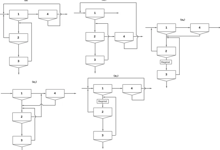
have any effect on improving the efficiency of plants. Over the past years, various circuit configurations havr been proposed by optimization
methods. The proposed optimal circuits are presented in Figure 4 using
a mathematical programming approach (a1 to a4).
Counter-current circuit contains two stages of cleaner and one
scavenger stage is shown in Figure 4a in order to compare with other
proposed circuits with four separation stages. As seen, several types of circuit configuration are proposed in terms of the objective function and the desired constraints for the 4-stage circuit. In all circuits, except the
a1, two cleaner stages and one scavenger stage are used. In addition, the
scavenger concentrate and the first cleaner tailings are returned. The proposed circuits by the genetic algorithm search method are
represented in Figure 5. Circuit b is a counter-current circuit consisting
of two stages of scavenger and one cleaner stage. Some of the GA suggested circuits are based on the designer's experience through eliminating the split streams.
Table 1. Recent research on optimization of flotation circuit configuration with mathematical programming and genetic algorithm.
Technique Year Highlights Weakness Source
Mathematical programming
2004 Introducing the MILP model for flotation circuit design
Extremely complex and many equations involved, difficulty
in linearization, high dependence on flotation models, single objective
[ 6 ]
2006 MILP application for designing flotation circuit containing
regrinding and column flotation ]27[
2009 MILP Application for flotation and classification circuits ]73[
2014 Investigating the objective function role in the design of the flotation circuit ]71[
2016 Mathematical optimization based on laboratory data ]22[
Genetic Algorithm
2005 Introduction of a genetic algorithm for flotation circuit configuration
Optimization
Require high memory and huge computations no guarantee for the optimal solution, weak mathematical
support, different responses for different runs
[ 55 ]
2006 Multi-objective optimization flotation circuits ]74[
2009 Determining the optimal configuration of the circuit with many stages ]26[
2011 Combination of genetic algorithm and circuit design rules ]25[
2013 Optimization of flotation circuit with pulp and froth phase models ]24[
2014 Pareto optimization using a genetic algorithm ]23[
As the number of separation stages increases, an optimization approach often faces the difficulty of finding the optimal configuration.
For example, for the niobec flowsheet [75], with a large number of
stages and a combination of different unit operations (Figure 6), the
application of a superstructure approach and consideration of all possible configuration, in addition to the huge volume of computations, will have difficulties in interpreting the results of the problem.
A review of previous studies found that [26] and [4] evaluated the
configuration of circuits with a large number of stages. In the first case, the arrangement of a circuit containing 15 separation units was
evaluated using the genetic algorithm [26]. The resulting circuits are
complex and have stream splits which were simplified according to the designer's experience. The second case was a 19-unit circuit, which was simplified by circuit analysis and separation sharpness criteria. The modified circuit has a lower number of streams and stages, while recovery and efficiency were higher.
5.
Summary and conclusion
A review of previous work has shown that one of the challenges of optimizing the circuit configuration is the creation of a large number of streams and the search for many unnecessary points. In addition to generating computational costs, this often leads to complicated or even impractical circuits. In contrast, the circuit analysis approach and considering the transfer function for the unit operations in the separation circuits provide the ability to perform a variety of circuit evaluations. In order to find the suitable and applicable configuration for circuits with a large number of stages, it is possible to first calculate feasible designs based on counter-current circuits. Also, reliable results will be provided by reducing the number of search point in addition to saving the volume of calculations.
Figure 4. four stage counter-current circuit (a) and optimal circuits from mathematical programming (a1 and a2) [6]; (a3 and a4) [27].
1
3
4 2
1
3
4
2
1
3
4
2
Regrind
1
3
4
2
Regrind
1
3
4
2
(a)
(a2)
(a3)
(a1)
Figure 5. Counter-current 4 stage circuit (b) and optimal circuits proposed with genetic algorithm (b1) [74]; (b2) [25]; (b3) [24].
Figure 6. Schematic flowsheet of niobec processing plant.
Acknowledgment
This research was funded by a Ph.D. grant of University of Tehran. We are grateful to the colleagues and professors at University of Tehran for sharing their pearls of wisdom with us during the course of this research.
REFERENCES
[1] Wills, B.A. and J. Finch, J. (2015). Wills' mineral processing technology: an introduction to the practical aspects of ore
treatment and mineral recovery. doi:
https://www.elsevier.com/books/wills-mineral-processing-technology/wills/978-0-08-097053-0.
[2] Mendez, D.A., Gálvez, E.D. and Cisternas, L.A. (2009). State of the art in the conceptual design of flotation circuits. International Journal of Mineral Processing, 2009. 90(1): p. 1-15.doi: https://doi.org/10.1016/j.minpro.2008.09.009
[3] Luckie, P.T., Staged solid–solid separations revisited. International Journal of Mineral Processing, 2003. 72(1-4): p. 455-462. doi: https://doi.org/10.1016/S0301-7516(03)00119-4 [4] McKeon, T. and Luttrell, G. (2012) Optimization of multistage
circuits for gravity concentration of heavy mineral sands. Minerals & Metallurgical Processin. 29(1). doi: http://mmp.smenet.org/abstract.cfm?aid=2685
[5] Amini, S.H. and Noble, A. (2017). Application of linear circuit analysis in evaluation of mineral processing circuit design under uncertainty. Minerals Engineering, 2017. 102: p. 18-29. doi: https://doi.org/10.1016/j.mineng.2016.12.002
[6] Cisternas, L. A., Gálvez, E. D., Zavala, M. F., & Magna, J., (2004). A MILP model for the design of mineral flotation circuits. International Journal of Mineral Processing. 74(1): p. 121-131. doi: https://doi.org/10.1016/j.minpro.2003.10.001
[7] Noble, A. and Luttrell, G.H. (2014). The matrix reduction
algorithm for solving separation circuits. Minerals
1 4
2
3
1 4
2
3 1 4
2
3
1 4
2
3
(b)
(b3) (b2)
(b1)
Tailings Concentrate
Feed
unit 23 unit 11 unit 5
unit 4 unit 3
unit 2 unit 1
unit 10
unit 9 unit 8
unit 7 unit 6
unit 16
unit 15 unit 14
unit 13 unit 12
unit 21 unit 20
unit 19 unit 18 unit 17
Engineering. 64: p. 97-108. doi:
https://doi.org/10.1016/j.mineng.2014.05.024
[8] Abu-Ali, M. and Sabour, S.A. (2003). Optimizing the design of
flotation circuits: an economic approach. Minerals
engineering. 16(1): p. 55-58. doi:
https://doi.org/10.1016/S0892-6875(02)00313-8
[9] Luttrell, G., Kohmuench, J. and Mankosa, M. (2004). Optimization of magnetic separator circuit configurations. transactions-society for mining metallurgy and exploration incorporated. 316: p. 153.
[10] Luttrell, G. H., Kohmuench, J. N., Stanley, F. L., & Trump, G. D. (1998). Improving spiral performance using circuit analysis. Minerals & metallurgical processing, 1998. 15(4): p. 16-21. doi:
[11] Loveday, B. and Brouckaert, C. (1995). An analysis of flotation circuit design principles. The Chemical Engineering Journal and The Biochemical Engineering Journal. 59(1): p. 15-21. doi: https://doi.org/10.1016/0923-0467(95)03001-8
[12] Hulbert, D., (1995). Optimization of counter-current flotation
circuits. The Chemical Engineering Journal and The
Biochemical Engineering Journal. 59(1): p. 7-13. doi: https://doi.org/10.1016/0923-0467(95)02999-0
[13] Williams, M. and Meloy, T. (1991). Feasible designs for
separation networks: a selection technique. International
journal of mineral processing. 32(3-4): p. 161-174. doi: https://doi.org/10.1016/0301-7516(91)90066-R
[14] Yingling, J.C., (1990). Circuit analysis: optimizing mineral processing flowsheet layouts and steady state control
specifications. International Journal of Mineral Processing.
29(3-4): p. 149-174. doi: https://doi.org/10.1016/0301-7516(90)90051-Y
[15] Williams, M., D. Fuerstenau, and Meloy, T. (1986). Circuit analysis—general product equations for multifeed, multistage
circuits containing variable selectivity functions.
International Journal of Mineral Processing. 17(1-2), 99-111. doi: https://doi.org/10.1016/0301-7516(86)90048-7
[16] Williams, M. and Meloy, T. (1983). Dynamic model of flotation cell banks—circuit analysis. International Journal of
Mineral Processing. 10(2): p. 141-160. doi:
https://doi.org/10.1016/0301-7516(83)90039-X
[17] Meloy, T., (1983). Optimizing for grade or profit in mineral processing circuits—Circuit analysis. International journal of
mineral processing. 11(2): p. 89-99. doi:
https://doi.org/10.1016/0301-7516(83)90002-9
[18] Meloy, T., (1983). Analysis and optimization of mineral processing and coal-cleaning circuits—circuit analysis. International Journal of Mineral Processing. 10(1), 61-80. doi: https://doi.org/10.1016/0301-7516(83)90033-9
[19] Sutherland, D., (1981). A study on the optimization of the
arrangement of flotation circuits. International Journal of
Mineral Processing. 7(4): p. 319-346. doi:
https://doi.org/10.1016/0301-7516(81)90027-2
[20] Cisternas, L. A., Lucay, F. A., Acosta-Flores, R., & Gálvez, E. D. (2018). A quasi-review of conceptual flotation design
methods based on computational optimization. Minerals
Engineering. 117: p. 24-33. doi:
https://doi.org/10.1016/j.mineng.2017.12.002
[21] Sepúlveda, F. D., Lucay, F., González, J. F., Cisternas, L. A., & Gálvez, E. D. (2017). A methodology for the conceptual design of flotation circuits by combining group contribution,
local/global sensitivity analysis, and reverse simulation. International Journal of Mineral Processing. 164: p. 56-66. doi: https://doi.org/10.1016/j.minpro.2017.05.008
[22] Calisaya, D. A., López-Valdivieso, A., Marcos, H., Gálvez, E. E., & Cisternas, L. A. (2016). A strategy for the identification of
optimal flotation circuits. Minerals Engineering. 96: p.
157-167. doi: https://doi.org/10.1016/j.mineng.2016.06.010
[23] Pirouzan, D., Yahyaei, M., & Banisi, S. (2014). Pareto based optimization of flotation cells configuration using an oriented genetic algorithm. International Journal of Mineral Processing. 126: p. 107-116. doi:
https://doi.org/10.1016/j.minpro.2013.12.001
[24] Hu, W., Hadler, K., Neethling, S. J., & Cilliers, J. J. (2013). Determining flotation circuit layout using genetic algorithms with pulp and froth models. Chemical Engineering Science. 102: p. 32-41.
[25] Ghobadi, P., Yahyaei, M., & Banisi, S. (2011). Optimization of the performance of flotation circuits using a genetic
algorithm oriented by process-based rules. International
Journal of Mineral Processing. 98(3): p. 174-181. doi: https://doi.org/10.1016/j.minpro.2010.11.009
[26] Guria, C., Varma, M., Gupta, S. K., & Mehrotra, S. P. (2009). Optimal synthesis of an industrial fluorspar beneficiation plant using a jumping gene adaptation of genetic algorithm.
Minerals and Metallurgical Processing. doi:
http://dspace.library.iitb.ac.in/xmlui/handle/10054/12002 [27] Cisternas, L. A., Méndez, D. A., Gálvez, E. D., & Jorquera, R. E.
(2006). A MILP model for design of flotation circuits with bank/column and regrind/no regrind selection. International Journal of Mineral Processing. 79(4): p. 253-263. doi: https://doi.org/10.1016/j.minpro.2006.03.005
[28] Leonzio, G. (2017). Optimization of column distillation in a
wastewater treatment plant. Journal of Environmental
Chemical Engineering: 5(6), 5732-5745. doi:
https://doi.org/10.1016/j.jece.2017.10.051
[29] Douglas, J. M. (1995). Synthesis of separation system
flowsheels. AIChE Journal. 41(12): p. 2522-2536. doi:
https://doi.org/10.1002/aic.690411203
[30] Yianatos, J., Carrasco, C., Bergh, L., Vinnett, L., & Torres, C. (2012). Modelling and simulation of rougher flotation circuits. International Journal of Mineral Processing. 112: p. 63-70. doi: https://doi.org/10.1016/j.minpro.2012.06.005 [31] Xian-ping, L., Xue-kun, T., Li-ping, H., & Li-ying, L. (2011).
Effects of size distribution on flotation kinetics of
Chalcopyrite. International Conference on Environment
Science and Engineering IPCBEE.
[32] Yianatos, J., & Contreras, F. (2010). Particle entrainment model for industrial flotation cells. Powder Technology, 2010.
197(3): p. 260-267. doi:
https://doi.org/10.1016/j.powtec.2009.10.001
[33] Yianatos, J., Bergh, L., Vinnett, L., Contreras, F., & Díaz, F. (2010). Flotation rate distribution in the collection zone of
industrial cells. Minerals Engineering. 23(11): p. 1030-1035.
doi: https://doi.org/10.1016/j.mineng.2010.05.008
[34] Saleh, A. M. (2010). A study on the performance of second order models and two phase models in iron ore flotation. Physicochemical Problems of Mineral Processing. 44(1): p. 215.
[35] Neethling, S. J., & Cilliers, J. J. (2009). The entrainment factor
parameter effects. International Journal of Mineral Processing. 93(2): p. 141-148. doi:
https://doi.org/10.1016/j.minpro.2009.07.004
[36] Neethling, S. J. (2008). Simple approximations for estimating froth recovery. International Journal of Mineral Processing. 89(1): p. 44-52. doi:
https://doi.org/10.1016/j.minpro.2008.09.007
[37] Uçurum, M., & Bayat, O. (2007). Effects of operating variables on modified flotation parameters in the mineral separation. Separation and Purification Technology. 55(2): p. 173-181. doi: https://doi.org/10.1016/j.seppur.2006.11.019
[38] King, R. P. (2012). Modeling and simulation of mineral
processing systems.Elsevier. doi:
https://search.proquest.com/docview/213821108?accountid=4 5153
[39] Rao, B. V. (2004). Weibull partition surface representation for gravity concentrators. Minerals engineering. 17(7-8): p. 953-956. doi: https://doi.org/10.1016/j.mineng.2004.03.001 [40] Lynch, A. J., Johnson, N. W., Manlapig, E. V., & Thorne, C. G.
(1981). Mineral and Coal Flotation Circuits-Their Simulation and Control.(Developments in Mineral Processing. No. 3). Elsevier Scientific Publishing Co., xiv+ 291, 24 x 16 cm, illustrated(USdollars U. S. 63. 50. doi:
10.1180/minmag.1981.044.335.27
[41] Kelsall, D. F. (1961). Application of probability in the assessment of flotation systems.
[42] Davis, W. J. W. (1964). The development of a mathematical model of the lead flotation circuit at the Zinc Corporation Ltd. Aus. IMM Proceedings. 212: p. 61-89.
[43] Fichera, M. A., & Chudacek, M. W. (1992). Batch cell flotation models—a review. Minerals Engineering. 5(1): p. 41-55. doi: https://doi.org/10.1016/0892-6875(92)90005-T
[44] Ferreira, J. P., & Loveday, B. K. (2000). An improved model
for simulation of flotation circuits.Minerals
Engineering,13(14-15), 1441-1453. doi:
https://doi.org/10.1016/S0892-6875(00)00129-1
[45] Mehrotra, S. P., & Kapur, P. C. (1974). Optimal-suboptimal synthesis and design of flotation circuits. Separation Science. 9(3), 167-184. doi: https://doi.org/10.1080/00372367408057055 [46] Kobayashi, S., Umeda, T., & Ichikawa, A. (1971). Synthesis of optimal heat exchange systems—an approach by the optimal
assingment problem in linear programming. Chemical
Engineering Science. 26(9): p. 1367-1380. doi: https://doi.org/10.1016/0009-2509(71)80057-X
[47] Reuter, M. A., & Van Deventer, J. S. J. (1990). The use of linear programming in the optimal design of flotation circuits incorporating regrind mills. International Journal of Mineral Processing. 28(1-2): p. 15-43. doi: https://doi.org/10.1016/0301-7516(90)90025-T
[48] Green, J. C. A. (1984). The optimisation of flotation networks. International journal of mineral processing. 13(2): p. 83-103. doi: https://doi.org/10.1016/0301-7516(84)90013-9
[49] Green, J. C. (1982). The design of a flotation network using
inequalities. Chemical Engineering Science. 37(9): p.
1353-1359. doi: https://doi.org/10.1016/0009-2509(82)85007-0 [50] Agar, G. E. (1980). Optimizing the design of flotation circuits.
Canadian Mining and Metallurgical Bulletin. 73(824): p. 173-181.
[51] Schena, G., Zanin, M., & Chiarandini, A. (1997). Procedures
for the automatic design of flotation networks. International journal of mineral processing. 52(2-3): p. 137-160. doi: https://doi.org/10.1016/S0301-7516(97)00065-3
[52] Schena, G., Villeneuve, J., & Noël, Y. (1996). A method for a financially efficient design of cell-based flotation circuits. International journal of mineral processing. 46(1-2): p. 1-20. doi: https://doi.org/10.1016/0301-7516(95)00082-8
[53] Boix, M., Montastruc, L., Azzaro-Pantel, C., & Domenech, S. (2015). Optimization methods applied to the design of
eco-industrial parks: a literature review. Journal of Cleaner
Production. 87: p. 303-317. doi:
https://doi.org/10.1016/j.jclepro.2014.09.032
[54] Goldberg, D. E., Deb, K., & Korb, B. (1990). Messy genetic
algorithms: Motivation, analysis, and first results. Complex
systems: 4(4), pp.415-444.
[55] Guria, C., Verma, M., Gupta, S. K., & Mehrotra, S. P. (2005). Simultaneous optimization of the performance of flotation
circuits and their simplification using the jumping gene
adaptations of genetic algorithm. International Journal of
Mineral Processing. 77(3): p. 165-185.
doi: https://doi.org/10.1016/j.minpro.2005.06.003
[56] Guria, C., Verma, M., Mehrotra, S. P., & Gupta, S. K. (2005). Multi-objective optimal synthesis and design of froth flotation circuits for mineral processing, using the jumping
gene adaptation of genetic algorithm. Industrial &
engineering chemistry research. 44(8): p. 2621-2633. doi: 10.1021/ie049706i
[57] Aickelin, U. and Dowsland, K.A. (2004) An indirect genetic
algorithm for a nurse-scheduling problem. Computers &
Operations Research. 31(5): p. 761-778.
[58] Lewis, R.M., Torczon, V. and Trosset, M.W. (2000) Direct search methods: then and now. Journal of computational and Applied Mathematics. 124(1-2): p. 191-207. doi: https://doi.org/10.1016/S0377-0427(00)00423-4
[59] Yingling, J. C. (1993). Parameter and configuration optimization of flotation circuits, part II. A new approach. International journal of mineral processing. 38(1-2): p. 41-66. doi: https://doi.org/10.1016/0301-7516(93)90063-G
[60] Hulbert, D., (2001) The optimum distribution of cell capacities in flotation circuits. Minerals engineering. 14(5): p. 473-486.
[61] Meloy, T. P., Clark, N., & Glista, J. J. (1986). Effect of density variations in heavy-media rougher-cleaner-scavenger cells— circuit analysis. International journal of mineral processing. 16(3-4): p. 169-178. doi: https://doi.org/10.1016/0301-7516(86)90029-3
[62] Williams, M. C., & Meloy, T. P. (1989). On the definition and
separation of fundamental process functions. International
Journal of Mineral Processing. 26(1): p. 65-72. doi: https://doi.org/10.1016/0301-7516(89)90043-4
[63] Williams, M. C., Fuerstenau, D. W., & Meloy, T. P. (1992). A graph-theoretic approach to process plant design. International journal of mineral processing. 36(1-2), 1-8. doi: https://doi.org/10.1016/0301-7516(92)90059-6
[64] Taggart, A.F. and Behre, H.A. (1945). Handbook of mineral dressing, ores and industrial minerals. Vol. 1: John Wiley & Sons.
[66] Tao, D., Luttrell, G. H., & Yoon, R. H. (2000). An experimental investigation on column flotation circuit configuration. International journal of mineral processing. 60(1): p. 37-56. doi: https://doi.org/10.1016/S0301-7516(00)00002-8
[67] Lucay, F., Mellado, M. E., Cisternas, L. A., & Gálvez, E. D. (2012). Sensitivity analysis of separation circuits. International Journal of Mineral Processing. 110: p. 30-45. doi: https://doi.org/10.1016/j.minpro.2012.03.004
[68] Flowsheets, M. M. P. (1962). Denver Equipment Company. Denver, Colorado.
[69] Luttrell, G. H., Forrest, W. R., & Mankosa, M. J. (2002). Development of an ideal separation curve for dry beneficiation. (02-178): p. 25-27.
[70] Harris, C. C., & Cuadros-Paz, A. (1978). Species interaction in
flotation: a laboratory-scale semi-batch study. International
Journal of Mineral Processing. 5(3): p. 267-283. doi: https://doi.org/10.1016/0301-7516(78)90023-6
[71] Cisternas, L. A., Lucay, F., & Gálvez, E. D. (2014). Effect of the objective function in the design of concentration plants.
Minerals Engineering. 63: p. 16-24. doi: https://doi.org/10.1016/j.mineng.2013.10.007
[72] Mehrotra, S. P. (1988). Design of optimal flotation circuits—a review. Miner. Metall. Process. 5: p. 142-152.
[73] Méndez, D. A., Gálvez, E. D., & Cisternas, L. A. (2009). Modeling of grinding and classification circuits as applied to
the design of flotation processes. Computers & Chemical
Engineering. 33(1): p. 97-111. doi:
https://doi.org/10.1016/j.compchemeng.2008.07.008
[74] Guria, C., Varma, M., Mehrotra, S. P., & Gupta, S. K. (2006). Simultaneous optimization of the performance of flotation circuits and their simplification using the jumping gene adaptations of genetic algorithm-II: More complex problems. International Journal of Mineral Processing. 79(3): p. 149-166. doi: https://doi.org/10.1016/j.minpro.2006.01.008
![Figure 5. Counter-current 4 stage circuit (b) and optimal circuits proposed with genetic algorithm (b 1) [74]; (b2) [25]; (b3) [24].](https://thumb-us.123doks.com/thumbv2/123dok_us/8956822.1866190/8.595.79.502.288.538/figure-counter-current-circuit-optimal-circuits-proposed-algorithm.webp)
