Simulating Random Voltage or Current Sources
In SPICE
Report NDT12-07-2007
3 July 2007
Copyright © 2007 by NanoDotTek™
Permission is granted to reproduce this report provided that appropriate credit is given to NanoDotTek™ as its author. However, this document is not to be reproduced for sale or profit.
Disclaimer: Best effort has been made in the preparation of this report. However, NanoDotTek™ makes no representations or warranties with respect to the accuracy or completeness of the contents of this report, and specifically disclaims any implied warranties of merchantability or fitness for any purpose. NanoDotTek™ shall not be liable for any loss of profit or any other commercial damages, including but not limited to special, incidental, consequential, or other damages.
1. Introduction
In this report we consider how to simulate random voltage (or current) sources in SPICE. The general approach described below involves interpolating a simulated white noise sequence. The word “interpolation” here is used in the sense familiar to numerical analysts (Zarowski [1]; see Chapter 6). The simulated white noise sequence is obtained outside of SPICE by another software tool. In principle, this could be quite literally any other general use programming language or software tool capable of outputting simulated random sequences. In this report we employ GNU Octave 2.1.73 as the tool for creating simulated random sequences. We also work with the SPICE implementation known as SwitcherCAD III (a.k.a. LTspice™) by Linear Technology Corporation.
The simulation approach provided here is quite different from the approaches suggested in [2]. It is suggested in [2] that random sources be simulated in one of two main ways:
1) Use the noise models for electronic devices (e.g., diodes).
2) Use arbitrary behavioral voltage/current sources in combination with the rand() or random() functions provided by SwitcherCAD III.
Both approaches require creating a suitable circuit (or subcircuit) that SwitcherCAD III must simulate to produce the desired result. These will be collectively referred to as circuit-based approaches to random source simulation.
The alternative interpolation approach considered here will be described within the framework of the theory of cyclostationary (CS) random processes (Gardner and Franks [3], Gardner [4], Gardner, Napolitano, Paura [5]). This is necessary to properly account for the generally periodic structure inherent in the simulated random process. For reasons explained in later sections we will interpolate based on using second-order cardinal B-splines (Chui [6]). It will be seen that interpolating a white noise sequence does not lead to an analog white noise process. In practice, the interpolation strategy only approximates bandlimited analog white noise (Ziemer and Tranter [7]). However, this will be seen to be adequate for the simulation of noise in electronic systems. There is a relationship between the interpolation approach and the uniform sampling theorem for lowpass signals [7]1. This will be remarked upon at the appropriate juncture.
Some possible advantages of the interpolation approach are:
1) At least in principle there is unlimited control over simulated process statistical characteristics afforded to the user. For example, the approach bypasses the pseudorandom number generator (PRNG) that is built in to SwitcherCAD III. It is therefore possible for a user to work with what might be a statistically better PRNG2.
1 This sampling theorem is also known as Shannon’s sampling theorem, or also as the Whittaker-Shannon-Kotel’nikov (WSK) sampling theorem (A. I. Zayed, Advances in Shannon’s Sampling Theory, CRC Press, 1993).
2) There is no need to create a circuit or subcircuit within SwitcherCAD III to simulate the desired random process. In this way the simulator is “unburdened.” 3) Some of the random process simulation methods proposed in [2] need “fudge
factors” to get things to come out just right. This is error-prone and not convenient.
Some possible disadvantages of the interpolation approach are:
1) The user must work with a software tool outside of SwitcherCAD III creating “system integration issues.”
2) Extending the approach presented here to accommodate other problems implies adequate mathematical sophistication on the part of the user.
3) There may be a runtime penalty in having SwitcherCAD III read in possibly long simulated random process descriptions from text files. It is not at all clear at this writing which of the interpolation approach or the circuit-based approaches are more runtime efficient and under what conditions.
These lists may not be exhaustive.
Finally, the analytical results presented here are certainly well known. The only exception might be the analytical (i.e., closed-form) expressions for the cyclic autocorrelation functions in Section 4. This report emphasizes the issue of whiteness and other matters (e.g., random process descriptions in terms of probability density functions) are omitted.
2. Using GNU Octave with SPICE
A typical SPICE implementation will provide the ability to simulate various types of ideal and independent voltage or current sources. However, the simplest constructions involve working with such entities as sinusoids, exponentials, rectangular pulses (periodic or mono-cycle), and piecewise-linear (PWL) constructions.
This report emphasizes the simulation of analog random processes using PWL constructions as these are so easy to work with. A specific and simple example of how to implement this approach using GNU Octave 2.1.73 and SwitcherCAD III appears in the Appendix.
3. White Noise
In this report we emphasize the problem of approximating white noise. The reason for this is simply that this is a basic building block for non-white (colored) noise processes. White noise may be filtered to arrive at random processes with highly diverse spectral characteristics.
White Noise Sequence
As noted in the Introduction we may simulate a random analog signal by interpolating a simulated random sequence here denoted by{xn}. We do not make any assumptions about the joint probability distributions for the sequence of random variables that model the “experimental” realization{xn}. In particular, the Gaussian assumption is not essential here. We only assume that the sequence is at least wide-sense stationary (WSS) (defined in [7]; see Section 5.2), and also that it is a zero mean and white noise (WN) process: m n m n n E x x x
E[ ]0, [ ]2 for all integers n, and m (3.1)
] [A
E denotes the expected value of random variable A. As well, {n}is the Kronecker delta sequence (a.k.a. unit sample sequence). This sequence is equal to one for n = 0 but is otherwise zero-valued. Note that the noise variance 2is the same thing as the double-sided power spectral density N0 /2 discussed in [7] (see Examples 5.5, and 5.6 and the subsection on noise-equivalent bandwidth).
White Analog Signal
An analog white random process has the following properties which are in close analogy to the previously discussed white noise sequence.
Suppose this process is denoted x(t). It is WSS. We will also assume that it is
zero-mean and so E[x(t)]0for all time t (real-valued). The autocorrelation function is ) ( )] ( ) ( [ ) ( 2 E x t x t Rx (3.2)
Here ()is the Dirac impulse concentrated at the origin 0. The power spectral density (PSD) of analog white noise is the Fourier transform of (3.2). We employ the following commonplace definitions of the Fourier transform (FT) and the inverse Fourier transform (IFT), respectively:
F f t f t e dt f t F F F e d F j t ( ) j t 2 1 )} ( { ) ( , ) ( )} ( { ) ( 1 (3.3)As well 2f so if fis in Hz then ω will be in radians/second. Therefore, the PSD of analog white noise is
2 )} ( { ) ( x x F R S (3.4)
Typical units are V2 /Hz(volts-squared per Hertz). It is apparent that (3.4) is a constant for all frequencies. Moreover, no real-world random process can be truly white since (3.4) implies that such a process has infinite power. In other words, white noise is a mathematical fiction, albeit a very convenient one.
A more practical alternative to white noise is the concept of bandlimited white noise. It is defined in terms of PSD according to
otherwise Sn B , 0 | | , ) ( 2 (3.5)
Thus, this PSD is some non-zero constant value only over some finite band of frequencies. The underlying random process n(t) now has finite power3. We may define B via B 2B. The autocorrelation function corresponding to (3.5) is (via the IFT)
2 2 2 2 ) sin( 2 ) ( d B e R B B B j n
sinc(2B) (3.6)where sinc(x) = sin(x)/(x). This is the “sinc-pulse.” This definition4 is implemented in
GNU Octave 2.1.73 as a built-in function.
Finally, we remark that (3.1) (and (3.2)) involves an abuse of notation that is common in the signal processing community. That is, normally a random variable is denoted in upper case. Thus, we should properly say that Xn is the nth random variable in some bi-infinite sequence of random variables whereas xnis a particular realization of this random variable (i.e., the particular outcome of a random experiment). This in turn implies that, for example, we should have written E[Xn] rather than E[xn]. However, context may be used to ascribe the correct meanings in practice, hence the popularity of this abuse. If the reader is not comfortable with this sort of thinking and these kinds of distinctions then we refer him/her to basic texts on applied probability for engineers or scientists of which there are many to choose from. One example of such a text is Leon-Garcia [8]. An introduction to applied probability theory also appears in [7].
4. Piecewise-linear Interpolation
In this section we define a certain PWL analog random process. We will also study certain of its statistical characteristics. This is where the theory of cyclostationary random processes will come into play. Ultimately we show how the PWL process may be used to adequately approximate bandlimited white noise.
3 However, process
n(t) is still not physically realizable because it is not causal. To “synthesize” it requires passing white noise through an ideal lowpass filter which is a non-causal system.
First of all, define the unit step function 0 , 0 0 , 1 ) ( t t t u (4.1)
We will be working with this function quite a lot.
Now suppose that we obtain {xn}by uniformly sampling the WSS analog processx(t). That is,xn x(nt), where t 0is the sampling period. If signalx(t)is zero mean and white (Section 3) then the sample sequence {xn}will be zero mean and white according to (3.1). Next we form a new random analog signal by linear interpolation which is formally described by the series
( ) ( )
) ( ) ( 1 1
n n n n n n n t t u t t u x t t t x x t x (4.2)where tn ntare the sampling times. Study of (4.2) reveals that it linearly interpolates the points (tn,xn) and (tn1,xn1). The random process (4.2) is only an approximation to x(t). We shall investigate the quality of this approximation later on.
A Second-order Cardinal B-spline Representation
The representation for our PWL approximation in (4.2) is very cumbersome to work with for analytical purposes. There is a much more concise representation based on working with cardinal B-splines [6] which we consider here. These are denoted by Nm(x)in [6] which represents the mth order cardinal B-spline.
The first order B-spline is ) 1 ( ) ( ) ( 1 x u x u x N (4.3)
A sketch reveals that this is simply a unit height square pulse defined (supported) on the unit interval [0,1]. The higher-order splines are obtainable in varied ways such as repeated integration via
1 0 1( ) ) (x N x t dt Nm m (4.4) factors m m x N x N x N x N ( ) 1( )* 1( )* * 1( ) (4.5)
The asterisk “*” denotes linear convolution according to the familiar definition which is
f t g d t g t f( )* ( ) ( ) ( ) (4.6)Consideration of (4.5) and (4.3) tells us that Nm(x)only has support on the interval [0,m]. Yet another formula for the general B-spline is (Equation (4.1.12) in [6])
) ( ) ( ) 1 ( )! 1 ( 1 ) ( 1 0 k x u k x k m m x N m m k k m
(4.7)It is apparent from (4.7) that splines are piecewise-polynomial constructions. In particular the second-order B-spline is piecewise-linear (PWL):
) 2 ( ) 2 ( ) 1 ( ) 1 ( 2 ) ( ) ( 2 t tu t t u t t u t N (4.8)
A plot appears in Fig. 1 (below). For convenience we will from now on write ) ( ) (t N2 t p . 0 0.2 0.4 0.6 0.8 1 0 0.5 1 1.5 2 p (t ) t
Second-order Cardinal B-spline
p(t)
With no loss of generality we will assume that the length (duration) of a line segment is
1
t unit (seconds if you prefer). This apparent restriction will later be removed by the elementary application of the scaling property for the Fourier transform. As a result the messy expression (4.2) is now replaced by the nice and compact expression
n n p t n x t x( ) ( 1) (4.9)For this to be a true interpolating series (Chapter 6 of [1]) it is necessary that (4.9) recover the given sequence when evaluated on the integers. This holds true here since
n k np k n x x k x( ) ( 1) (4.10)To see this it helps to view the plot in Fig. 1, but only looking at the cases for integer t. Results on the Process Statistics
We must now study the mean and the autocorrelation of the random process (4.9). We shall discover that even though {xn}is a white noise process, x(t) is not even WSS much less white. We shall prove that it is cyclostationary (CS), and then use the mathematical framework afforded by this theory to design x(t) so that it adequately approximates a bandlimited white noise process.
The mean value of the random process x(t) in (4.9) is
n n n n x t E x t E x p t n E x p t n m ( ) [ ( )] ( 1) [ ] ( 1) 0 (4.11)for all t. The autocorrelation function is
m x t E x t x t p t m p t m R ( ,) [ ( ) ( )] 2 ( ) ( ) (4.12)We observe that both the time origin which is defined with respect to t and the lag τ determine this function. This implies that the random process x(t) is non-stationary in spite of the fact that {xn}is a white noise sequence described by (3.1). However, it is easy to confirm that
) , ( ) , 1 (t R t Rx x (4.13)
That is, the autocorrelation function is periodic with respect to t and the period is one unit. This means that x(t) is a cyclostationary (CS) random process. As suggested in [3], [4] or [5] we may therefore express (4.12) as a complex Fourier series
n nt j n x x t R e R ( ,) () 2 (4.14)where the Fourier series coefficients are given by
1 0 2 ) , ( ) ( R t e dt Rxn x j nt (4.15)The function Rxn()is called a cyclic autocorrelation function, and the integers n in this
context are called the cycle frequencies. (More generally, if the process had period T then the cycle frequencies would be n/T.) From (4.12) Equation (4.15) can be rewritten as
dt e t p t p dt e t p t p R t n j m m m t n j n x
2 2 1 2 2 ) ( ) ( ) ( ) ( ) ( (4.16) The corresponding PSD () { n()} x n x F RS is called the cyclic spectrum at cycle frequency n.
We may try to simplify (4.12) by averaging over one period to eliminate dependence with respect to t. The result is
dx x p x p dx x p x p dt n t p n t p dt t t R R m m m n x x ) ( ) ( ) ( ) ( ) ( ) ( ) , ( ) ( ~ 2 1 2 1 0 2 1 0 (4.17)This amounts to pretending that x(t) is a stationary process. This is an over-simplification. However, it is important to observe that
) ( ) ( ~ 0 x x R R (4.18)
In fact, as noted in [3] or [5] the Fourier series expansion in (4.14) will be that of a WSS random process provided that n()0
x
R for all n0. For a white process we also require that R0x()have the form in (3.2). Yet it is clear from p(t) given in (4.8) that the
integral at the end of (4.17) is not a Dirac pulse. It is not even a good approximation to one. And from (4.16) it should also be clear that n()0
x
R for all τ when n0. Exact expressions for the cyclic autocorrelation functions are considered below.
Now we need to investigate if there are any conditions under which x(t) can usefully approximate a white noise process. This involves a more detailed study of the structure of Rnx()and especially of the cyclic spectra Sxn(). In fact, we see that
) 2 ( ) ( ) ( ) ( ) ( ) ( ) ( ) ( ) ( ) ( 2 ) 2 ( 2 ) 2 ( ) ( 2 2 2
n P P t x via dt e t p dx e x p dt e t p d e t p dt d e e t p t p S t n j x j t n j t j j t n j n x (4.19)This is a simple and informative expression. Because we are working with spline interpolants it is easy to get closed-form expressions for our particular problem. Recall from (4.5) that ) ( ) ( ) (t N1 t N1 t p (4.20)
while from the direct application of the definition of the Fourier transform
2 / ) 2 / sin( )} ( { 1 /2 j e t N F (4.21)
Hence by application of the convolution theorem for the Fourier transform we have
2 2 1( )}] sin(/2/2) { [ ) ( F N t e j P (4.22)
Therefore, the last equation in (4.19) now becomes 2 2 2 2 2 2 2 sin 2 2 sin ) ( n n Sxn (4.23)
The special case n = 0 may be singled out and is
4 2 0 2 / ) 2 / sin( ) ( x S (4.24)
Now observe that
4 2 1 1 1 1( )* ( )* ( )* ( )} sin(/2/2) { j e t N t N t N t N F (4.25)
The shifting theorem for the Fourier transform states that ) ( )} ( {f t e F F j (4.26)
Neglecting the real-valued scaling by 2in (4.24) we now see that (4.24) and (4.25) represent the same pulse except for a relative time delay of two units. Referring to (4.5) we now see that Rx0()is really just a fourth-order cardinal B-spline. Once again, this is
nothing like a Dirac pulse.
It is easy to see that the cyclic spectra are real-valued and always non-negative. There is also the symmetry condition
) ( ) ( n x n x S S (4.27)
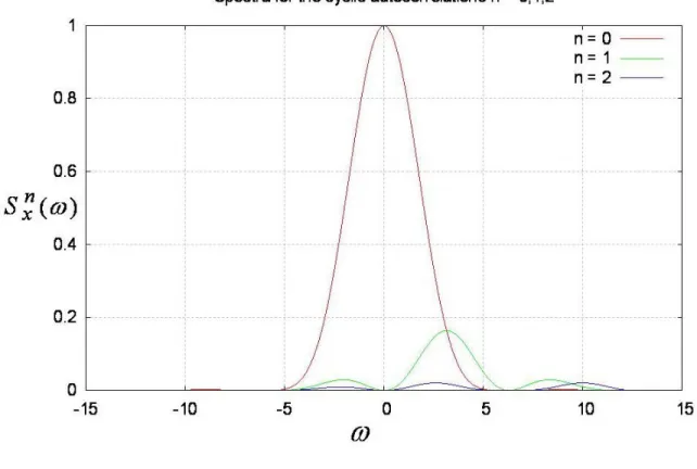
Therefore, we really need only consider n0. Figure 2 (below) displays the first few
cyclic spectra assuming that 2 1. In (4.14) the terms for n0may be regarded as
interference terms. We see from Fig. 2 that these terms seem to quickly weaken with increasing n. Also, and importantly, the interference is weak in the vicinity of 0(that is, close to DC). If we think in terms of trying to approximate bandlimited white noise instead of white noise then S0x()approximates (3.5) provided thatis small enough.
Figure 2: The first three cyclic spectra (n = 0,1,2 in (4.23) and 2 1) for PWL interpolation synthesis of a random process.
The closed-form expression (4.23) was easily obtained. We also have a simple expression for R0x() if we choose to make use of (4.7). Unfortunately, the expressions for
) (
n x
R when n0are not so nice though they are obtainable. We will provide them mainly for completeness though they are not essential to our main purpose.
The process of deriving closed-form expressions for higher-order cyclic autocorrelation functions is simplified by a careful study of the regions of support of the functions involved, and by working with p(t) as given by (4.8). In particular, Fig. 1 indicates that p(t) is non-zero only for t[0,2]. The integrand of (4.16) (last equation) has the product
) ( )
(t p t
p . Plotting this on the t-axis for various τ we conclude that
] 2 , 2 [ 0 ) ( for Rxn (4.28)
Also from a study of (4.16) we find the symmetry condition
) ( ) ( j2n xn n x e R R (4.29)
This means that we really only need to look at either [2,0], or [0,2]. Moreover, the integration limits in (4.16) can be restricted to t[0,2] (instead of t(,) the entire real number line). Additional study of the structure of the integrand in (4.16) reveals that we need the integral
2( 2 ) ) , , , | ( d t j dt e c bt at d c b a f (4.30)It is understood that f(|a,b,c,d)0for all d 2. Note that
2 3 2 2 2 2 2 , 1 , 1 t t e dt e t t e dt te e dt e t t t t t t (4.31)Of course, for our problem j, and in fact 2n. From (4.31) we find that (4.30) becomes 2 3 2 2 2 2 2 ) , , , | ( t d t t c b a t a b t a e d c b a f (4.32)
It can be shown that
j n n x Q n e R ( ) 2 (2 , ) 2 (4.33)
where [0,2], and n1,2,3,. The “Big Q” in (4.33) is given by
) 1 ), 1 ( 4 ), 2 ( 4 , 4 | ( ) 1 , 0 ), 1 ( 2 , 2 | ( ) , 2 ), 1 ( 2 , 2 | ( ) , 0 , , 1 | ( ) , ( f f d f f Q (4.34) The “d” in the second term on the right-hand side of (4.34) is evaluated according to
1 , 1 , 1 d (4.35)
That is, there are two cases to consider.
We conclude this subsection by observing that * )] ( [ ) ( n x n x R R (4.36)
1 2 0( ) 2 Re[ ( ) ] ) , ( n nt j n x x x t R R e R (4.37)The operation Re[g(t)] means “take the real part of g(t).” Therefore, we need only study the cyclic autocorrelation functions for n0,1,2,3,.
A Simple Design Approach
As has been noted above it is not possible to synthesize white noise by any means if for no other reason than infinite power signals do not exist. This poses no real problem for electronic circuit simulation, however. In practice an electronic circuit is bandlimited. Suppose its bandwidth is BW. An input signal with components having frequencies less than BW will pass, but any components with frequencies above BW will be removed. Therefore, in practice if x(t) is bandlimited white noise of bandwidth B > BW the electronic circuit will respond to it as though the noise were truly white according to (3.2) (or (3.4)).
Now, we have analyzed the spectral characteristics of the PWL random process in (4.9) and discovered that the spectrum is reasonably flat for small ω. However, we need practical design criteria to exploit this idea. A little later on we will make use of the scaling property for the Fourier transform which is
) 0 ( / ) / ( )} ( {x at X a a a F (4.38)
This will allow us to work with 0t 1. We now specify a simple approach for doing
so.
Power levels are normally expressed in decibels (dB):
) ( log 10 ) ( 10 xn n x dB S S (4.39)
Clearly, Sx0(0)2 which is the peak value of Sx0(). This PSD rolls off monotonically from its peak value until the first zero which occurs at 2 . Recalling that 2 f , and defining (as before)B 2Bwe will consider the PSD Sx0()to be “flat” for f [0,B] such that
dB x B x A S S ) 0 ( ) ( log 10 0 0 10 (4.40)
where AdB is some acceptable amount of attenuation over [0,B] (e.g., } 1 . 0 , 5 . 0 , 1 , 2 , 3 { dB
1) The PSD Sx0() is not really very flat over [0,B] in this case.
2) The terms in (4.37) for n0will be associated with in-band (periodic)
interference.
(Recall that B for 3 dB of attenuation is the half-power point.) In practice we shall likely prefer AdB 1dB. From AdB 10log10 Ait is not hard to use (4.40) to obtain the following nonlinear equation for B:
0 10
)
sin(B AdB/40B (4.41)
Simple numerical methods to solve this are presented in [1]. GNU Octave has a nonlinear programming toolbox with routines to solve (4.41) (e.g., fminbnd)5.
dB A B (assumes t1) 3 0.31839 2 0.26150 1 0.18599 0.5 0.13190 0.1 0.059123
Table 1: Cutoff frequencies for which S0x()is acceptably flat ([0,B],B 2B).
Table 1 above lists various cutoff frequencies B for certain attenuations. We may assume
1
t second and so B in Table 1 has the units of Hz. Clearly, B is not very big and so we can only simulate white noise inputs to very narrowband electronic systems. To accommodate real-world bandwidths we need to reducet. For a desired noise bandwidth B Band upon applying (4.38) the desired segment length is given by
B B t (seconds) (4.42)
This follows because we use x(t/t)in place of x(t). From (4.38) we have Bt B and so (4.42) immediately arises.
Now we choose BBWwith the choice based on an acceptable flatness; B in (4.42) is appropriately chosen from Table 1. As we expect, the flatter the PSD of Fig. 2 (case n = 0) in the desired band, the smaller we need to make B and the shorter twill become.
5 Function fminbnd implements the golden section search method for locating the minimum of a scalar-valued function with a scalar argument. The problem of solving (4.41) can be converted to a simple function minimization problem.
For a test signal x(t) (from (4.9)) of desired duration T (seconds) we need to generate B T B t T N (4.43)
line segments. (Rounding to an integer value is assumed in evaluating (4.43).) We prefer to use as small an N as possible and so tshould be as large as possible to minimize the number of required segments. Using fewer line segments places less of a burden on SPICE. However, a good quality test signal means that B must be small and so N will be large. So, there is an inevitable tradeoff involved here.
As a simple example suppose that we want a bandlimited white noise process with bandwidth B1 MHz. Suppose that AdB 1 dB is an adequate amount of flatness for our purpose. Therefore, from (4.42) we must employ a PWL synthesis with segment lengths of t0.18599/B0.18599sec. If we now wish to create a test signal of
length T 100sec then from (4.43) we need N 100/0.18599538 line segments. If the sequence {xn}is Gaussian then the GNU Octave randn() function may be used to obtain the sequence elements, assuming a Gaussian process is desired.
The next section points out that the ideal method of interpolating the sequence }
{xn involves using sinc-pulses. But if sinc-pulses are the ideal choice then why don’t we use them instead of PWL interpolation ? Recall that
sinc(t) t t ) sin( (4.44)
This signal is not finitely supported as it is defined over the entire real number line. It is much messier to implement sources in SPICE using (4.44) than PWL constructions. Moreover, trying to accurately approximate a sinc-pulse with simpler functions (e.g., PWL approximation) needs a complicated representation due to the slow decay of the sinc-pulse with respect to time t.
Recall as well that function (4.44) is the impulse response of an ideal lowpass analog filter. The theory of filter design centers around creating useful causal approximations to (4.44). The plethora of methods for doing this really underscores the difficulty of obtaining “nice” approximations to (4.44).
5. Sinc-pulse Interpolation
Here we show that the ideal interpolating function is really the sinc-pulse. It was briefly argued at the end of Section 4 that this choice is not so easy to implement hence our practical preference for the PWL construction in (4.9). Nevertheless, considering the ideal case gives us a frame of reference to judge the quality of the approximation (4.9). It gives us a useful perspective on the design equations (4.42), and (4.43).
In this section p(t) is redefined to be (4.44). In this case otherwise u u P , 0 , 1 ) ( ) ( ) ( (5.1)
The interpolating series (4.9) is now replaced with
n n c t n x t x( ) sin ( ) (5.2)With this we are continuing to assume that the spacing between consecutive elements of }
{xn is t 1(second). We may confirm that (5.2) does indeed interpolate the input sequence because k n n k n n n c k n x x x k x
) ( sin ) ( (5.3)Similarly to (4.12) we now have
n x t c t n c t n R ( ,) 2 sin ( )sin ( ) (5.4)and (4.13) also holds. However, we will see that x(t) in (5.2) is actually WSS ! This is most easily shown by viewing expressions for the cyclic spectra. Of course
c t c t e dt Rxn() 2 sin ( )sin ( ) j2nt (5.5)which are the cyclic autocorrelation functions. The general expression at the end of (4.19) continues to hold in our new situation. Thus,
) 2 ( ) ( )} ( { ) ( F R 2P P n Sxn xn (5.6)
This is evaluated using (5.1). Immediately we discover that
0 , 0 0 , ) ( ) ( 2 n n P Sxn (5.7)
We conclude that x(t) defined by the series (5.2) is WSS and also bandlimited white noise with bandwidth B 2B (radians/second). Thus, B0.5Hz.
This implies that if our electronic circuit again has bandwidth BW and that Bis the desired noise bandwidth such that B BW 0.5we must space the sequence samples
according to sampling interval
B t
0.5 (seconds) (5.8)
Comparing this expression with (4.42) while keeping in mind the entries of Table 1 we see that using sinc-pulse interpolation requires fewer pulses to simulate a bandlimited white noise process of some pre-determined duration T compared to the number of line segments needed in the PWL synthesis of Section 4. Sinc-pulse interpolation is more efficient in this way than PWL interpolation. But again the sinc-pulse is harder to work with in practice.
The connection between (5.8) and Shannon’s sampling theorem should be clear. Recall that an analog signal bandlimited to BHz must be sampled at a minimum rate of 2BHz in order for the acquired samples to permit a perfect reconstruction of the entire original analog signal via a sinc-pulse interpolating series such as that illustrated by (5.2).
Appendix
The following GNU Octave script writes a SPICE directive specifying an ideal independent voltage source to the file myV1.txt:
---% % Make_myV1.m % function Make_myV1 outfile = fopen("myV1.txt","w"); fprintf(outfile,"%s","V1 VR1 0 PWL("); t = [ 0 .1 .9 1.0]; x = [ 0 1 1 0 ]; for k = 1:length(t) fprintf(outfile,"%8.4f%8.4f",t(k),x(k)); endfor;
fprintf(outfile,"%s",") Rser=0 Cpar =0"); fclose(outfile);
When the above script is run the following text will be written to file myV1.txt. It is a SPICE directive creating the desired voltage source via piecewise-linear (PWL) construction:
V1 VR1 0 PWL( 0.0000 0.0000 0.1000 1.0000 0.9000 1.0000 1.0000 0.0000) Rser=0 Cpar =0
SwitcherCAD III favors schematic-based descriptions of circuits. The simplest example of how to make use of output from Make_myV1.m is illustrated as follows which is a schematic contained in a file called ArbitaryVoltageSource.asc:
We see the SPICE directive .inc myV1.txt. When the transient simulation is run the file myV1.txt will be read and interpreted as a directive to implement the desired source. Here the directive specifies a trapezoidal pulse shape. Consequently, typical circuit signal traces are as follows:
It is not hard to edit the previous GNU Octave script to synthesize any desired PWL test signal including simulated random processes designed according to the theory in the main body of the present report (see especially the last subsection of Section 4). Limited experimentation shows that SwitcherCAD III will accept source descriptions containing at least thousands of line segments.
Acknowledgment
Various software tools were employed in the production of this report. GNU Octave 2.1.73 and SwitcherCAD III (a SPICE implementation by Linear Technology Corporation) both running under MS Windows XP were all employed in the “number crunching” and the production of illustrative figures. PDF Online™, a free online file type conversion service was used to convert the MS Word version of this report into pdf. Input from the LTspice™ technical group (particularly from H. Sennewald) is much appreciated.
References
1. C. J. Zarowski, An Introduction to Numerical Analysis for Electrical and Computer Engineers, John Wiley and Sons, 2004.
2. http://tech.groups.yahoo.com/group/LTspice/
3. W. A. Gardner, L. E. Franks, “Characterization of Cyclostationary Random Signal Processes,” IEEE Trans. on Information Theory, vol. IT-21, no. 1, Jan. 1975, pp. 4-14.
4. W. A. Gardner, “Exploitation of Spectral Redundancy in Cyclostationary Signals,” IEEE Signal Processing Magazine, April 1991, pp. 14-36.
5. W. A. Gardner, A. Napolitano, L. Paura, “Cyclostationarity: Half a Century of Research,” Signal Processing, v. 86, 2006, pp. 639-697.
6. C. K. Chui, An Introduction to Wavelets, Academic Press, 1992.
7. R. E. Ziemer, W. H. Tranter, Principles of Communications: Systems, Modulation, and Noise, Houghton Mifflin, 1976.
8. A. Leon-Garcia, Probability and Random Processes for Electrical Engineering (2nd edition), Addison-Wesley, 1994.
![Figure 1: The second-order cardinal B-spline ( N 2 ( t ) in Chui [6]).](https://thumb-us.123doks.com/thumbv2/123dok_us/10131494.2914045/8.918.226.698.670.966/figure-second-order-cardinal-b-spline-n-chui.webp)
![Table 1: Cutoff frequencies for which S 0 x ( ) is acceptably flat ( [ 0 , B ] , B 2 B ).](https://thumb-us.123doks.com/thumbv2/123dok_us/10131494.2914045/16.918.289.657.424.637/table-cutoff-frequencies-s-acceptably-flat-b-b.webp)
