Systems With Carrier Aggregation
by
Ran Zhang
A thesis
presented to the University of Waterloo in fulfillment of the
thesis requirement for the degree of Doctor of Philosophy
in
Electrical and Computer Engineering
Waterloo, Ontario, Canada, 2016
c
I hereby declare that I am the sole author of this thesis. This is a true copy of the thesis, including any required final revisions, as accepted by my examiners.
In order to meet the ever-increasing demand for wireless broadband services from fast grow-ing mobile users, the Long Term Evolution -Advanced (LTE-A) standard has been pro-posed to effectively improve the system capacity and the spectral efficiency for the fourth-generation (4G) wireless mobile communications. Many advanced techniques are incorpo-rated in LTE-A systems to jointly ameliorate system performance, among which Carrier Ag-gregation (CA) is considered as one of the most promising improvements that has profound significance even in the upcoming 5G era. Component carriers (CCs) from various portions of the spectrum are logically concatenated to form a much larger virtual band, resulting in remarkable boosted system capacity and user data throughput.
However, the unique features of CA have posed many emerging challenges as well as span-new opportunities on the Radio Resource Management (RRM) in the LTE-A systems. First, although multi-CC transmission can bring higher throughput, it may incur more inten-sive interference for each CC and more power consumption for users. Thus the performance gain of CA under different conditions needs fully evaluating. Besides, as CA offers flexible CC selection and cross-CC load balancing and scheduling, enhanced RRM strategies should be designed to further optimize the overall resource utilization. In addition, CA enables the frequency reuse on a CC resolution, adding another dimension to inter-cell interference man-agement in heterogeneous networks (HetNets). New interference manman-agement mechanisms should be designed to take the advantage of CA. Last but not least, CA empowers the LTE-A systems to aggregate the licensed spectrum with the unlicensed spectrum, thus offering a capacity surge. Yet how to balance the traffic between licensed and unlicensed spectrum and how to achieve a harmony coexistence with other unlicensed systems are still open issues.
To this end, the dissertation emphasizes on the new functionalities introduced by CA to optimize the RRM performance in LTE-A systems. The main objectives are four-fold: 1) to fully evaluate the benefits of CA from different perspectives under different conditions via both theoretical analysis and simulations; 2) to design cross-layer CC selection, packet scheduling and power control strategies to optimize the target performance; 3) to analytically
model the interference of HetNets with CA and propose dynamic interference mitigation strategies in a CA scenario; and 4) to investigate the impact of LTE transmissions on other unlicensed systems and develop enhanced RRM mechanisms for harmony coexistence.
To achieve these objectives, we first analyze the benefits of CA via investigating the user accommodation capabilities of the system in the downlink admission control process. The LTE-A users with CA capabilities and the legacy LTE users are considered. Analytical models are developed to derive the maximum number of users that can be admitted into the system given the user QoS requirements and traffic features. The results show that with only a slightly higher spectrum utilization, the system can admit as much as twice LTE-A users than LTE users when the user traffic is bursty. Second, we study the RRM in the single-tier LTE-A system and propose a cross-layer dynamic CC selection and power control strategy for uplink CA. Specifically, the uplink power offset effects caused by multi-CC transmis-sion are considered. An estimation method for user bandwidth allocation is developed and a combinatorial optimization problem is formulated to improve the user throughput via maxi-mizing the user power utilization. Third, we explore the interference management problem in multi-tier HetNets considering the CC-resolution frequency reuse. An analytical model is devised to capture the randomness behaviors of the femtocells exploiting the stochastic geometry theory. The interaction between the base stations of different tiers are formulated into a two-level Stackelberg game, and a backward induction method is exploited to obtain the Nash equilibrium. Last, we focus on the mechanism design for licensed and unlicensed spectrum aggregation. An LTE MAC protocol on unlicensed spectrum is developed con-sidering the coexistence with the Wi-Fi systems. The protocol captures the asynchronous nature of Wi-Fi transmissions in time-slotted LTE frame structure and strike a tunable trade-off between LTE and Wi-Fi performance. Analytical analysis is also presented to reveal the essential relation among different parameters of the two systems.
In summary, the dissertation aims at fully evaluating the benefits of CA in different sce-narios and making full use of the benefits to develop efficient and effective RRM strategies for better LTE-Advanced system performance.
There are many people I wish to express my sincere gratitude and appreciation who have made this thesis successful and meaningful. First of all, I wish to express my sincere gratitude to my supervisors, Professor Xuemin (Sherman) Shen and Professor Liang-liang Xie, for their invaluable and constant guidance throughout my graduate studies in University of Waterloo. During years of extensive training they provided me, they not only inspired me on how to conduct research in the cutting-edge field, but also profoundly shapes my thinking to be precise, logic, and sharp. More importantly, they recruited a smart, lovely and charming lady that I will cherish for my whole life as a husband.
I am grateful to have an examining committee with distinguished scholars. I would like to thank Professor Zhou Wang, Professor Fakhri Karray, and Professor Xinzhi Liu for their helpful comments and insightful questions. I would like to thank Professor Abdallah Shami from Western University for his commitment and serving as my external examining committee member.
I would like to thank all my friends and colleagues in the Broadband Communications Research Group, University of Waterloo. My sincere appreciation is extended to all friends and co-workers for their friendship and interaction. Special thanks go to Professor Lin X. Cai from Illinois Institute of Technology, Professor Rongxing Lu from Nanyang Technological University, and Professor Hao Liang from University of Alberta for their great encourage-ment and constructive discussions along the way. I am also grateful to Professor Yu Cheng from Illinois Institute of Technology, Dr. Zhongming Zheng, Dr. Ning Lu, Dr. Ning Zhang, Dr. Amila Gamage, Dr. Jian Qiao, Dr. Qinghua Shen, Qiang Ye, Nan Cheng, Kuan Zhang, Jianbing Ni, and Wenchao Xu for their expertise and friendship.
Last, but not the least, I am much obliged to my parents, Guangshui Zhang and Jinghong Zhang, my little sister, Yiwei Zhang, and my beloved wife, Dr. Miao Wang, for their uncon-ditional love, understanding and support in my life.
List of Figures . . . xii
List of Tables . . . xiii
Abbreviations . . . xiv
1 Introduction 1 1.1 Overview of LTE-A Systems . . . 2
1.1.1 Architecture of LTE-A Systems . . . 2
1.1.2 Characteristics of LTE-A Systems . . . 4
1.2 Carrier Aggregation (CA) . . . 5
1.2.1 Design Principles . . . 5
1.2.2 Characteristics of CA . . . 6
1.2.3 Spectrum Access in LTE-A Systems with CA . . . 9
1.3 RRM Framework for LTE-A Systems with CA . . . 10
1.3.1 Hierarchical User Plane . . . 10
1.3.2 RRM Functionalities and Considerations . . . 12
1.4 Organizations and Contributions . . . 13
2 Research Topics and Related Works on RRM in LTE-A Systems with CA 14 2.1 Benefit Demonstration of CA . . . 15
2.2 CA in Single-Tier LTE-A Systems . . . 17
2.3 CA in Multi-Tier LTE-A Systems . . . 19
2.5 Dissertation Objectives . . . 25
2.6 Summary . . . 27
3 Equivalent Capacity Analysis in Carrier Aggregation-Based LTE-A Systems 28 3.1 Models and Design Goal . . . 30
3.1.1 Traffic Generating Model . . . 31
3.1.2 Bandwidth Sharing Model . . . 32
3.1.3 Definition of EC . . . 33
3.1.4 Design Goal . . . 34
3.2 Equivalent Capacities with Fixed Bandwidth Allocation Weights . . . 34
3.2.1 Effective Bandwidth from User Throughput Requirement . . . 35
3.2.2 Equivalent Capacity for a Single Carrier . . . 37
3.2.3 Equivalent Capacity in Multi-Carrier LTE-A Systems . . . 41
3.3 Equivalent Capacities with Cognitive Bandwidth Allocation Weights . . . . 42
3.3.1 Single-Carrier Case . . . 43
3.3.2 Multi-Carrier Case: LTE vs. LTE-A users . . . 47
3.4 Net-Profit Maximization Under Different Bandwidth Allocation Strategies . 49 3.4.1 Fixed-Weight Bandwidth Allocation Strategy . . . 50
3.4.2 Cognitive-Weight Bandwidth Allocation Strategy . . . 51
3.5 Performance Evaluation . . . 52
3.5.1 Effective Bandwidth . . . 52
3.5.2 Fixed-Weight Strategy . . . 53
3.5.3 Cognitive-Weight Strategy . . . 56
3.5.4 Performance Comparison between Two Strategies . . . 58
3.6 Summary . . . 60
4 Cross-Layer Carrier Selection and Power Control for LTE-A Uplink with CA 61 4.1 System Model . . . 62
4.3 Performance Evaluation . . . 68
4.3.1 Simulation Setup . . . 68
4.3.2 Simulation Results . . . 70
4.4 Summary . . . 73
5 Probabilistic QoS Provisioning in LTE-A HetNets with Partial Spectrum Usage 75 5.1 System Model . . . 76
5.1.1 Network Deployment . . . 76
5.1.2 Bandwidth Allocation Mechanisms . . . 77
5.1.3 Physical Channel Model . . . 79
5.1.4 Economic Interaction between Macro and Femto Cells . . . 79
5.2 Probabilistic Analysis on User Performance for HetNets with PSU . . . 80
5.2.1 SINR Distributions and User Ergodic Rates . . . 80
5.2.2 User Service Probability and Bandwidth Usage Probability . . . . 83
5.2.3 QoS-Aware Effective Bandwidth: Formulation and Algorithm . . . 85
5.3 Two-Level Stackelberg Game Between Macro and Femto Cells . . . 88
5.3.1 Game Formulation . . . 88
5.3.2 Analysis of the Proposed Game . . . 90
5.4 Performance Evaluation . . . 92
5.4.1 Simulation Setup . . . 92
5.4.2 Numerical and Simulation Results . . . 92
5.5 Summary . . . 96
6 Modeling and Analysis of MAC Protocol for LTE-U Coexisting with Wi-Fi 97 6.1 System Model . . . 98
6.1.1 Co-existence Scenario . . . 98
6.2 The Proposed LBT-Based MAC for LTE-Unlicensed . . . 99 6.3 Performance Analysis for LTE-U LBT-Based Coexistence Mechanism . . . 101 6.3.1 Average Number of Sensing Periods to Retrieve the Channel Access 102 6.3.2 Average System Throughput for LTE-U and Wi-Fi Systems . . . . 107 6.4 Performance Evaluation . . . 110 6.5 Summary . . . 112
7 Conclusions and Future Works 113
7.1 Conclusions . . . 113 7.2 Future Research . . . 114
7.2.1 Cross-Layer CC Selection and (De)activation for CA-Based LTE-A systems115 7.2.2 Interference Management in “Green” HetNets with CA . . . 115 7.2.3 Traffic Balancing between Licensed Spectrum to Unlicensed spectrum116
8 Related Publications 118
8.1 Books and Book Chapters . . . 118 8.2 Journal Papers . . . 118 8.3 Conference Papers . . . 120
1.1 The Architecture of LTE-A Systems . . . 3
1.2 Three different CA types. . . 7
1.3 Bandwidth structure for LTE-A systems based on OFDMA. . . 9
1.4 Hierarchical user plane and the corresponding RRM functionalities . . . 11
2.1 Deployment scenarios of LTE-U technology. . . 22
2.2 Research path of the dissertation on RRM in CA-based LTE-A systems. . . 25
3.1 Voronoi cells formed by9BSs uniformly located within a10kmx10kmarea. 30 3.2 On-off traffic generation model of one user. . . 31
3.3 Composite traffic model for the system states . . . 38
3.4 Effective bandwidth vs.ru k under differentevalues. . . 53
3.5 Fixed-weight strategy: ECs under 4 different parameters . . . 54
3.6 Fixed-weight strategy: The EC relation between 2 user classes . . . 56
3.7 Cognitive-weight strategy: ECs of class-2 users under different parameters. 57 3.8 Cognitive-weight strategy: ECs of class-2 users with changingωmax l1 . . . 58
3.9 EC comparison between two strategies. . . 58
3.10 Annual average hourly number of users per cell in the tested cell. . . 58
3.11 Net profits comparison between two strategies. . . 58
4.1 User fairness under different values of∆tandN . . . 71
4.3 CC occupation per user vs. average user inter-arrival time . . . 72
4.4 CC occupation per user vs. average user inter-arrival time . . . 72
5.1 The network layout of HetNets. . . 77
5.2 Bandwidth structure of HetNets under PSU. . . 78
5.3 User SINR and ergodic throughput performance in HetNets. . . 94
5.4 Effective bandwidth with different minimum throughput requirements. . . . 95
5.5 The optimal PSU policy of FBS (nresandnopen) given differenty. . . 95
5.6 The optimal interference price and PSU policy for different CA capabilities. 96 6.1 Coexistence scenario between LTE-U and Wi-Fi. . . 98
6.2 LBT-based MAC protocol of LTE-U. . . 100
6.3 Illustration of two types of FO Wi-Fi transmissions. . . 103
6.4 Illustration of four cases for FO transmissions. . . 105 6.5 Failure probability for the LTE-U BS to reserve the channel in one subframe. 111 6.6 Average system throughput of LTE-U and Wi-Fi with Wi-Fi protection level. 111 6.7 Adjustment of WTX to different Wi-Fi protection levels withTSP = 200µs. 112
1.1 Technical comparison between LTE and LTE-A with IMT-A requirements . 4
3.1 Simulation Parameters I . . . 52
3.2 Simulation Parameters II . . . 53
4.1 Main Default Simulation Parameters . . . 70
5.1 Simulation Parameters . . . 93
6.1 Notation Table . . . 102
Abbreviations
3GPP the Third Generation Partnership Project
ACCS Autonomous Component Carrier Selection
CA Carrier Aggregation
CC Component Carrier
CoMP Coordinated Multi-Point Transmission
DRX Discontinuous Reception
EC Equivalent Capacity
eICIC enhanced Inter-cell Interference Coordination
FBS Femtocell Base Station
HARQ Hybrid Automatic Repeat Request
HetNet Heterogeneous Networks
IMT International Mobile Telecommunication
ISP Internet Service Provider
ITU International Telecommunication Union
LBT Listen-before-Talk Mechanism
LTE-A Long Term Evolution - Advanced
LTE-U Long-Term Evolution Unlicensed System
MAC Medium Access Control
OFDMA Orthogonal Frequency Division Multiple Access
PCell Primary Cell
PDCP Packet Data Convergence Protocol
PHY Physical Layer
(P)RB (Physical) Resource Block
PSU Partial Spectrum Usage
QoS Quality of Service
RLC Radio Link Control
RRC Radio Resource Control
RRM Radio Resource Management
SBS Small Base Station
SCell Secondary Cell
SC-FDMA Single-Carrier Frequency Division Multiple Access
TTI Transmission Time Interval
Chapter 1
Introduction
With the challenges presented by the ever increasing use of “smart” wireless devices that require significantly higher spectral resources than conventional cell-phones, providing high quality of service for mobile applications in a cost-effective manner becomes increasingly important for operators to meet consumer needs. Towards this end, the International T-elecommunication Union (ITU) has initiated a global standard initiative - International Mo-bile Telecommunication - Advanced (IMT-A) for 4G moMo-bile communications in 2007 [1]. IMT-A systems include exciting new capabilities for providing a wide range of telecommuni-cation services and applitelecommuni-cations, stressing improved quality of service (QoS) and worldwide development. To support enhanced user and service demands, peak data rate targets of 100 Mb/s for high mobility and 1 Gb/s for low mobility are established for IMT-A.
In response to ITUs invitation of candidate proposals for IMT-A, the Third Generation Partnership Project (3GPP) started Long Term Evolution -Advanced (LTE-A) in 2008 [2] which was ratified as an IMT-A technology in November 2010. LTE-A builds upon the 3GPP Release 8/9 specification, known as LTE [3], which is widely accepted as the transi-tion standard from 3G to 4G. Although LTE systems could provide peak data rates of 300 Mb/s in the downlink (highest capability terminals) and 75 Mb/s in the uplink with scalable bandwidths of up to 20MHz, the the IMT-A data-rate requirements are still not satisfied. To fulfill the IMT-A requirements, LTE-Advanced shall support wider bandwidths than LTE
use a single carrier. In practice, such a large portion of continuous spectrum is rarely avail-able. Carrier aggregation (CA) [4–6], where multiple component carriers (CCs) of smaller bandwidth are aggregated, is an attractive alternative to increase data rate. Additional advan-tages are offered by CA in terms of spectrum efficiency, deployment flexibility, backward compatibility, and more. By aggregating non-contiguous carriers, fragmented spectrum can be more efficiently utilized. Various deployment scenarios for homogeneous and heteroge-neous networks are supported by CA with proper utilization of different carriers. With each CC being LTE compatible, CA allows operators to migrate from LTE to LTE-A while con-tinuing service to LTE users. Both implementation and specification efforts are minimized by reusing the LTE design on each of the CCs.
In this section, we will first present a brief overview of the LTE-A systems and the CA technology. The related works on Radio Resource Management (RRM) in LTE-A systems with CA are then introduced, in which the existing challenges and problems to be solved are proposed as part of our research motivations.
1.1
Overview of LTE-A Systems
1.1.1
Architecture of LTE-A Systems
Historically, mobile networks have consisted of a single homogeneous “layer” of macro cells of broadly uniform size. However, as the density of user equipments (UEs) increases, smaller cells are needed to deliver sufficient capacity. Since the small cells are introduced in a pre-existing network of macro cells, the result is a heterogeneous network (HetNet) of macro and small cells operating at different transmission powers and with different coverage areas. The HetNet architecture of the LTE-A systems are shown in Fig. 1.1.
The system layout of LTE-A is a HetNet where one macro cell is overlaid with a group of small cells and relays. A macrocell base station (MBS) in LTE-A systems is called the
1.1. Overview of LTE-A Systems Relay Femto Cell Macro Cell Core Network Relay Backhaul Pico Backhaul ISP Internet Femto Backhaul eNB1 eNB2 Micro/Pico Cell
Figure 1.1. The Architecture of LTE-A Systems
enhanced NodeB (eNB) since the capability of the base station (BS) is enhanced with R-RM and part of the mobility management functionalities, which are usually performed in the radio network controller (RNC) in the 3G cellular radio access network [7]. An addi-tional funcaddi-tionality is introduced in the LTE-A systems, which configures multiple MBSs to cooperatively communicate with one cell-edge user for performance improvement [8].
The small BSs (SBSs) operate on the same spectrum with the MBSs and are typically installed to extend the coverage to indoor areas where outdoor signals do not reach well or to add network capacity in areas with very dense service usage, e.g., train station. SBSs can provide high-data-rate services to the users in a small coverage range with relatively small transmission power, thus being low-cost and easy to be deployed. The small cells are basically divided into three types, i.e., the microcells, the picocells and the femtocells. The microcells and picocells are usually deployed by the vendors and has direct backhaul to the eNBs (MBSs) through wireline, which means the RRM and mobility management of the picocells are controlled directly by the MBSs. While the femtocell is usually deployed by the end users and its backhaul to the cellular core network is through the Internet service providers (ISPs). Thus the femtocells have larger signaling latency and the deployment is harder to be predicted and controlled by the MBSs. Generally, the transmission range of the
microcells is less than2km. A picocell, on the other hand, is 200mor less, and a femtocell is on the order of 10m [9]. Besides, relays are deployed to improve the performance of cell-edge users. Different from the small cells, the backhaul link of the relays is wireless, meaning that all the control signalings and data flows between relays and the eNB must be transmitted wirelessly, thus occupying some bandwidth resources of the eNB. However, compared to the small cells, relays have the lowest deployment cost.
1.1.2
Characteristics of LTE-A Systems
Fulfilling the standard requirements of the IMT-A, LTE-A systems can achieve much higher system capacity and spectrum efficiency than the LTE systems. Table 1.1 gives a compre-hensive technical comparisons among LTE, LTE-A and the IMT-A requirements [10].
Items LTE LTE-A IMT-A
Downlink peak rate with CA 300 Mb/s 3 Gb/s 1 Gb/s
Uplink peak rate with MIMO 75 Mb/s 500 Mb/s N/A
Supported bandwidth (MHz) Up to 20 Up to 100 5-20
Radio access technology Dowlink: OFDMA Uplink: SC-FDMA
Downlink: OFDMA
Uplink: hybrid OFDMA/SC-FDMA N/A Downlink spectrum efficiency
(bps/Hz) 16.3 30.6 15
Uplink spectrum efficiency
(bps/hz) 4.3 16.8 6.75
Table 1.1 Technical comparison between LTE and LTE-A with IMT-A requirements From the table, it can be seen that LTE-A can achieve much higher peak data rate and spectrum efficiency than LTE and satisfy all the IMT-A requirements. The LTE system supports scalable bandwidths of up to 20 MHz providing peak data rates of 300 Mb/s in the downlink (highest capability terminals) and 75 Mb/s in the uplink. However, the LTE systems still cannot satisfy the IMT-Advanced requirements in peak data rates and spectral efficiency. To settle this problem, LTE-A exploits CA to combine at most five CCs (i.e., LTE carriers), each has a bandwidth of up to 20MHz [11], to aggregate small bandwidth segments into a wider bandwidth for one transmission, thus enhancing the system capacity by multiple times. At the same time, more advanced MIMO techniques are adopted in the
1.2. Carrier Aggregation (CA)
system with more spatial layers (concurrent transmitted information flows) in both downlink and uplink [10]. Together with the MIMO technique with full spatial multiplexing gain, the peak data rate of LTE-A can achieve 3Gb/s in downlink and 500 Mb/s in uplink [12].
For the radio access technologies, both LTE-A and LTE adopt the orthogonal frequency division multiple access (OFDMA) [13] in the downlink; however, in the uplink, LTE adopts the single carrier frequency division multiple access (SC-FDMA) [13], while LTE-A adopts hybrid OFDMA/SC-FDMA. The different in the uplink is due to the backward compatibility in the design of LTE-A systems. Building upon the LTE systems, a LTE-A system must be designed in such a way that the legacy LTE users who can only use SC-FDMA in the uplink can operate normally in the system, being compatible with all the additional enhanced functionalities.
1.2
Carrier Aggregation (CA)
As one of the most momentous techniques in LTE-A, Carrier Aggregation (CA) allows s-calable bandwidth extension via aggregating multiple smaller band segments, each called a Component Carrier (CC), into a wider virtual frequency band to transmit at higher rates [14]. The following subsections give a brief introduction on the CA design principles and man-agement characteristics.
1.2.1
Design Principles
The design of 3GPP LTE-A CA considers various aspects including backward compatibil-ity, system modification, implementation complexcompatibil-ity, and so on with the following design principles [14].
1. Backward Compatibility - Backward compatibility is critical for LTE-A CA to mi-grate smoothly from LTE and reuse the LTE design to the most extent. Each CC in LTE-A is LTE backward compatible, i.e, accessible by the LTE UE. The complete set
of LTE downlink transmissions are performed on each CC following the LTE physical procedure and specifications.
2. Minimum Protocol Modifications- From the aspect of user-plane protocols, the CCs are invisible to the Packet Data Convergence Protocol (PDCP) and radio link control (RLC) layers. The multiple CCs are only different data transmission pipes managed by a single scheduling entity at the medium access control (MAC) layer. Each CC has its own LTE-compatible hybrid automatic repeat request (HARQ) processes for the physical (PHY) layer transmissions. The PHY and MAC design for 3GPP LTE-A supports up to 5 CCs despite of the CA types.
3. Limited Control Procedure Impact- In the control-plane aspect, radio resource con-trol (RRC) entity assigns the radio management information from the network to the UE. At a given time instance, one UE is in either RRC IDLE or RRC CONNECTED state. One UE can transmit/receive data to/from the network only when it is R-RC CONNECTED. One RR-RC IDLE UE shall transit to RR-RC CONNECTED state by establishing an RRC connection following the LTE procedure before being able to transmit on multiple CCs. Hence, LTE-A CA does not change the RRC IDLE proce-dures; nor does it impact the establishment procedure of an RRC connection.
1.2.2
Characteristics of CA
Types of CA
LTE-A systems support three types of CA: intra-band contiguous CA, intra-band non-contiguous CA and inter-band CA, as shown in Fig. 1.2. For the first type, all the aggregated CCs are located within the same frequency band (e.g., the GSM @900MHz) and are contiguous one by one. The CCs in the second type are also located within the same frequency band but may not be contiguous to each other. As the CCs of the first two types are both located within the same band, the radio characteristics (e.g., the channel fading statistics) of each CC can
1.2. Carrier Aggregation (CA)
CC 1 CC 2
...
CC nCC 1 CC 2
...
CC n(a) Intra-band Contiguous CA
GSM @ 900MHz f f (b) Intra-band Non-Contiguous CA GSM @ 900MHz CC 1 CC 2
...
CC n f (c) Inter-band Non-Contiguous CA GSM @ 900MHz CDMA @ 1.9GHzFigure 1.2. Three different CA types.
be considered identical. In the third type, CCs can be located in different frequency bands (e.g., GSM and CDMA bands), thus having different radio characteristics which should be carefully considered into the RRM framework for inter-band CA.
Adaptive CC Selection/Configuration
In LTE-A CA, a CC is often referred to as a serving cell and is treated as such by the higher layer procedures. For frequency-division duplex (FDD), a serving cell comprises a pair of different carrier frequencies for downlink and uplink transmissions. For time-division duplex (TDD), a serving cell is defined for a single carrier frequency where downlink and uplink transmissions occur in different transmission time intervals (TTI). Each UE has a single serving cell that provides all necessary control information and fuctions, such as mobility and security information, RRC connection maintenance, etc. This serving cell is referred to as the primary cell (PCell). Other serving cells are referred to as secondary cells (SCells).
Cell management is the control procedure in layer 3 (i.e., the network layer) enabling the network to add/remove/change an SCell or to switch the PCell of UE. AN RRC IDLE UE establishes an RRC connection toward a serving cell, which automatically becomes its PCell. Depending on the carrier where initial access is performed, different UEs in a CA system may have different PCells. With the RRC connection on the PCell, the network can
further configure one or more SCells for UE within the UE CA capability to meet traffic demands. The necessary information, including system information, of an SCell is conveyed to the UE via dedicated RRC signaling. Addition, removal, and reconfiguration of SCells to a UE are also performed via dedicated RRC signaling. The network can further change the PCell of a UE, for example, to improve the link quality of the PCell on which critical control information is sent or to provide load balancing among different SCells. PCell change in CA can only be performed via the handover procedure. PCell change does not necessarily require UE to switch to single-CC operation. Intra-LTE handover in LTE-A allows the target PCell to configure one or more SCells for UE to use immediately after handover.
Dynamic CC Activation/Deactivation
Cell activation/deactivation is a mechanism in MAC layer aiming to reduce UE power con-sumption in CA on top of discontinuous reception (DRX) [15], which is already supported in LTE Release 8/9. DRX puts UE into power saving mode when the UE is not expected to receive data from the network. According to network configuration and ongoing HARQ pro-cesses, UE determines the DRX ON/OFF duration common to all serving cells. To further reduce UE battery consumption, an SCell in CA can be activated or deactivated [16]. For a deactivated SCell, UE does not receive any downlink signal; nor does the UE transmit any u-plink signal. Conversely, for an activated SCell, UE performs normal activities for downlink reception and uplink transmission. The SCell activation/deactivation is enabled by a combi-nation of explicit and implicit means where the network can issue an activation/deactivation command in the form of a MAC control element (CE), or the UE autonomously deactivates a serving cell upon timer expiry. Serving cell activation/deactivation is performed indepen-dently for each SCell, allowing UE to be activated only on a necessary set of SCells. Acti-vation/deactivation is not applicable for the PCell since the functions provided by the PCell require it to always remain activated when the UE has an RRC connection to the network.
1.2. Carrier Aggregation (CA)
1.2.3
Spectrum Access in LTE-A Systems with CA
Spectrum Access on CC Resolution
Each BS can dynamically select from a finite set of available CCs. Each MBSs are accessible to all the available CCs while for the densely deployed SBSs, each node only uses a subset of available CCs. This is the best configuration for optimizing the system performance as there is severe interference coupling between those nodes. Notice that by conducting the adaptive frequency reuse on CC resolution, both data and control channels experience benefits within a single CC.
Spectrum Access on PRB Resolution
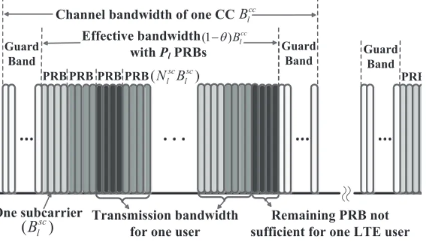
The bandwidth structure of one single CC is shown in Fig. 1.3. As shown in Fig. 1.3, the
···
PRB
Transmission bandwidth for one user
· · ·
One subcarrier Remaining PRB not
sufficient for one LTE user
Guard Band Effective bandwidth withPlPRBs ··· Guard Band
Channel bandwidth of one CC
··· PRB Guard Band cc l B (1 ) cc l B q -( sc) l B ( sc sc) l l N B PRB PRB PRB P
Figure 1.3. Bandwidth structure for LTE-A systems based on OFDMA.
channel bandwidthBcc
l of thelthCC is up to20MHz and contains two parts: the guard bands (GBs) and the transmission bandwidth. As specified in [17], the GBs are set on both sides of each CC to avoid interference caused by Doppler Shift and Frequency Aliasing Effect in real systems [18]. No effective data will be transmitted in the GBs. The total percentage of GBs is denoted asθ. For thelth CC, the transmission bandwidth is divided intoPl PRBs, each composed of Nlsc continuous subcarriers with bandwidth Blsc. The relationship of all
the above variables is given as Pl= (1−θ)Blcc Bsc l Nlsc , l= 1,2, ..., n, (1.1)
wherendenotes the number of CCs. The assignment of PRBs for each user is determined according to the throughput requirement and channel conditions. The interference from other users in the same cell is ignorable due to the orthogonality of PRBs. For LTE users, the transmission bandwidth may not be fully utilized as the remaining PRBs in one CC may not be sufficient to serve any more users. However, for LTE-A users, these unused PRBs in different CCs could be combined together to jointly serve a user through the CA technique. In this way, the LTE-A users could achieve higher spectrum usage than the LTE users. In this work, such PRBs are referred to assemi-usage PRBs.
1.3
RRM Framework for LTE-A Systems with CA
The RRM framework in LTE-A systems within our research scope involves the protocols and functionalities from layer 3 to layer 1. The overview of the hierarchical user plane and the corresponding mapping of the most essential RRM functionalities are shown in Fig. 1.4.
1.3.1
Hierarchical User Plane
The left part of Fig. 1.4 shows the user plane of CA within our research scope. Each user has at least one radio bear, carrying one data flow for the user. Different radio bears have different QoS provisions for service differentiation. Each radio bearer is associated with one data packet convergence protocol (PDCP) and radio link control (RLC), which are inherited from LTE Release 8 [19]. These two protocols perform functionalities such as robust head-er compression (ROHC), security, segmentation, and outhead-er automatic repeat request (ARQ). The interface between RLC and the medium access control (MAC) is refered to aslogical
1.3. RRM Framework for LTE-A Systems with CA
New User Arrival Admission Controlmissmissioioioioioioioioion ioioioioioioioioioion n n n CoCoCoCoCoCoCoContCoCoCoCoCoCont CC Selection/Configurationtion///Co//////CoCoCoCoCoCoConfig
Packet Scheduling Packet Scheduling Packet Scheduling TD Scheduling TD Scheduling TD Scheduling FD Scheduling FD Scheduling FD Scheduling FD Schchchchchedchededededededededededululin FD Schchchchchchedededededededededululin FD Schchchchchchchededuledededededededededededulin Link Adaptation & HARQ Link Adaptation & HARQ Link Adaptation & HARQ nk Adadadadadadadadadadadadadaptptptat Power Control HARQ
Cont Power Control Power Control HARQ Cont HARQ Cont . . . Layer 3 PDCP Layer 2 MAC Layer 1 @ CC #1 @ CC #2 @ CC #N MUX MU MU MUX Semi-dynamic CC (de)activation ROHC Security ROHC Security ROHC Security ... Segmentatio n Out er AR Q Segmentatio n Out er AR Q HARQ ...
Single scheduling and priority handling Multiplexor HARQ HARQ Segmentatio n Out er AR Q ...
PHY PHY ... PHY
@ CC #1 @ CC #2 @ CC #N Radio bearer #1 Radio bearer #2 Radio bearer #K ... Layer 2 RLC Layer 3 Layer 2 MAC sublayer Layer 1
Figure 1.4. Hierarchical user plane and the corresponding RRM functionalities
channels, which are further divided into control channels and traffic channels. Each user has one MAC entity, which multiplexes (MUX) the data from all the logical channels to the user (or eNB), and distributes the data to transmissions on different available CCs. As illustrated in Fig. 1.4, each CC has a separate HARQ entity, essentially meaning that the transmission and possible retransmissions of one packet are on the same CC. The interface between MAC and the physical layer (PHY) is denoted astransport channels, each mapping to one or more logic channels. The transport channels are also separate for each CC. Data transmission-s on different CCtransmission-s can adopt independent modulation and coding transmission-schemetransmission-s (MCStransmission-s). Atransmission-s a result, independent link adaptation (LA) per CC is enabled to benefit from optimally adjust-ing transmissions on different CCs accordadjust-ing to the correspondadjust-ing channel conditions. The power control for different CCs can also be independent, making it possible for one eNB to have diverse coverage levels on different CCs [14].
For the control-plane protocol of LTE-A CA, similarly as LTE Release 8, each user has one radio resource control (RRC) entity, which is independent of the number of CCs [19]. To fulfill the function of CA, a few more functionalities have been added into RRC, which will be elaborated in the next subsection.
1.3.2
RRM Functionalities and Considerations
The main RRM functionalities of LTE-A are presented in the right part of Fig. 1.4. The LTE-A RRM framework has many similarities with that of LTE Release 8/9. When a user arrives, the admission control is performed at the eNB before the establishment of the RRC connection. New radio bearers are then created and the corresponding QoS parameters are configured. Specifically, a new functionality is introduced into LTE-A CA, which is referred to as CC selection or configuration in the following. CC selection configures a set of CCs for each user to be scheduled on. This function is an important tache to optimize system performance over the entire CC set, as well as controlling the power consumption. The CC selection takes as inputs the information of QoS parameters, UE capabilities, radio bearer configuration, CC load and channel conditions. Among the inputs, the CC load conditions are used for cross-CC load balancing [19], and the QoS parameters specify the user service types (e.g., best-effort and guaranteed-bit-rate services) and the QoS requirements. For a UE, assigning more CCs can significantly increase its throughput, but resulting in higher UE power consumption and signaling overhead, as well as more interference to other UEs operating on the assigned CCs. Therefore, potential freedom is left for researchers to design optimal CC selection algorithms to achieve various performance objectives.
Same as LTE Release 8, in MAC layer of LTE-A systems, all the data flows from differ-ent users on one CC are multiplexed together, and the packet scheduling (PS) differ-entity in each CC will allocate PRBs to the attached users in every Transmission Time Interval (TTI) of
1ms. Basically, the PS takes advantage of multi-user frequency-domain scheduling diversity by preferentially allocating PRBs to users that are perceiving good channels. The PS pro-cess consists of two phases, i.e., time-domain PS and frequency-domain PS. The entity first determines which subset of users should be scheduled in the next TTI and then determines which part of and how much bandwidth should be allocated to each scheduled user.
However, there are two main differences between LTE-A PS and LTE PS. First, the PS in LTE-A is allowed to schedule users across multiple CCs. The scheduling could be
1.4. Organizations and Contributions
done in parallel in different CCs, but with some coordination to ensure fairness and joint control for users scheduled on multiple CCs [20]. This cross-CC scheduling functionality offers higher flexibility and better overall system performance for transmissions of control and data information across multiple CCs. Second, on top of the regular PS in each CC, an additional functionality is designed to dynamically (de)activate CCs configured as SCells for different users, which is controlled by MAC signalings through the PCell [16]. A user is only schedulable on its configured and activated SCCs and does not report channel state information (CSI) for link adaptation and frequency-domain PS through the SCCs. With this functionality, the number of CCs that a user can be scheduled on can be dynamically adjusted in tens of ms according to the instantaneous cell load conditions and QoS requirements. In this fashion, the UE power can be further preserved.
In addition, within each CC, link adaptation is performed to dynamically adjust the UE’s modulation and coding schemes according to the time-varying channel conditions; HARQ is performed to manage packet retransmissions when packet loss or error occurs. At last, the power control entity in Layer1 will decide the UE transmission power on each CC either independently or coordinately.
1.4
Organizations and Contributions
The remainder of the dissertation is organized as follows: Chapter 2 introduces the re-search topics on RRM in LTE-A systems with CA, and elaborates some related works to our most interest for each topic. Chapter 3 presents our research results on demonstrating the advantages of CA in improving the system limiting capabilities, i.e., the system user-accommodation capabilities. Chapter 4 investigates resource (i.e., spectrum and power) op-timization in single-tier LTE-A CA-based systems. Chapter 5 studies interference manage-ment problems in multi-tier LTE-A systems with CA. The conclusions and future research directions are presented in Chapter 7. Finally, Chapter 8 concludes the dissertation with our related publications.
Research Topics and Related Works on
RRM in LTE-A Systems with CA
Many research issues emerge in the realization process of CA-based LTE-A systems, among which RRM is very imperative in providing guidelines to fully utilize the network resources. Since OFDMA/SC-FDMA is adopted as the access technology in LTE-A standard, RRM in LTE-A systems can date back to the studies on RRM in OFDMA systems, where subcarrier is the minimum bandwidth allocation resolution. Most of the related studies [21–23] mainly focus on reorganizing the limited network resources to optimize the network performance. For instance, in [21], a novel scheme for the allocation of subcarriers, rates, and power was proposed to maximize the aggregated data rates. In [22], the energy efficiency problem was investigated for cognitive radio systems under the QoS constraints. In [23], the uplink relay selection problem was discussed to enhance the total achievable throughput under total pow-er constraint. We refpow-er to [24–26] as comprehensive surveys on RRM in OFDMA systems.
However, these works can not be directly applied to LTE and LTE-A systems due to the unique features of LTE-based systems. Different from subcarriers in OFDMA systems, the minimum resolution in LTE-based networks is Physical Resource Block (PRB) which is composed of 12 consecutive OFDM subcarriers. One user could be assigned with several PRBs but all the subcarriers in one PRB must be assigned to the same user. This feature
2.1. Benefit Demonstration of CA
significantly reduces the control overhead and meanwhile improves the spectrum utiliza-tion. It also gives rise to new challenges upon the design of scheduling and power allocation schemes for both control channels and data channels. Thus, the flexibility and efficiency of the existing works should be re-evaluated, and new schemes particularly for PRB allocation and power control should be considered. For instance, since the minimum bandwidth alloca-tion unit in LTE is the PRB, [27] put forward a distributed and coordinated PRB and power allocation scheme to mitigate the intercell interference in LTE. As the control channel struc-ture is updated in LTE over OFDMA systems, [28] showed different conditions when an LTE system is data-channel limited or control-channel limited. [29] further gave a comprehensive overview of downlink RRM for LTE systems.
Compared with LTE networks, the adopted CA technique in LTE-A systems also brings new challenges and favorable opportunities for RRM. With CA, an LTE-A user could operate on multiple CCs concurrently to have larger throughput. But operating on more CCs means more energy consumption at the user terminal and more intensive interference to other users operating on the same CCs. Thus, how to dynamically decide which CCs should be assigned to different users is a critical issue given the tradeoff among throughput, energy consumption and interference intensity. Besides, cross-CC load balancing and scheduling should also be deliberated to achieve better overall network resource utilization.
In light of these challenges, this chapter intends to uncover the main imperative issues on RRM of CA-based LTE-A systems in a systematic manner, and outline our research logic path as a whole towards tackling the open challenges.
2.1
Benefit Demonstration of CA
In CA-based LTE-A scenarios, the legacy LTE users and LTE-A users could co-exist and share the system bandwidth up to 100MHz, where LTE users can only be scheduled on one CC at any time while LTE-A users can transmit on multiple CCs concurrently with larger possible throughput. Then there rises a problem: given this advantage, how much the
performance of LTE-A users can surpass that of LTE users in different scenarios should be carefully studied to demonstrate the benefits of CA.
This problem can be explored from two perspectives, i.e., the user-centric perspective and the system-centric perspective. On one hand, given a set of users or an arrival-departure process of users, the user-centric performance (e.g., average throughput, user service de-lay [30] and power efficiency [31] in the user terminal) can be compared between LTE users and LTE-A users under different cell load conditions. There have already been many works following this thought [19, 20, 32]. For example, the work [19] focuses on comparing the throughput performance via simulations between the legacy LTE users and LTE-A users in a multi-CC LTE-A system. Simulation results shows that LTE-A users outperform the LTE users in terms of the average throughput and cell-edge throughput, especially in light cell load conditions. The work suggests that the number of CCs accessible per LTE-user should vary with the cell load conditions for better performance. In [20], a joint carrier load bal-ancing and packet scheduling scheme is put forward, comparing the average user throughput when LTE users and LTE-A users coexist under cross-CC scheduling. It is shown that the LTE-A users can achieve significantly higher throughput under different conditions when coexisting with LTE users. In [32], leveraging the stochastic geometry theory, analytical analysis is developed to derive the user SINR distributions and average throughput for LTE and LTE-A users, respectively. The results indicate that although LTE-A users can achieve higher throughput than LTE users, the perceived SINR is worse in a single CC for LTE-A users due to multi-CC transmissions. Thus, the performance gain may become smaller with larger number of cell users as the SINR situations for LTE-A users become worse faster.
On the other hand, this issue can be investigated from the system-centric perspective, i.e., to study the system limiting capabilities. For example, in the admission control process, given the same system settings and user QoS requirements, the user accommodation capa-bilities of LTE-A systems can be analyzed to show how many LTE users or LTE-A users can be admitted into the system. However, few works have dabbled in this issue from this perspective whereas it can provide valuable guidelines for optimizing resource utilization
2.2. CA in Single-Tier LTE-A Systems
and guaranteeing QoS provisioning at the same time. To this end, one of our research goals is to explore the performance improvement in the system limiting capabilities in different scenarios when CA is adopted, while jointly considering the QoS requirements (e.g., loss probability, throughput requirement) and traffic descriptors (e.g., active probabilities) of dif-ferent user types. Our research works [33, 34] have focused on this issue, where the LTE-A downlink admission control process is studied and a QoS-aware closed-form admissible re-gion for heterogeneous user classes are derived (See Chapter 3).
2.2
CA in Single-Tier LTE-A Systems
For LTE-A CA, it is not good to always assign multiple CCs to every user. On the contrary, in some cases the multi-CC transmission can significantly counterbalance the performance gain. For instance, for a best-effort user, assigning as many CCs as possible may be less op-timal when the cell load becomes quite heavy, since the extremely crowded situation in one CC can considerably reduce the average per-CC user throughput, resulting in a lower aggre-gate user throughput [19] [35]. On the other hand, for a user with a guaranteed throughput requirement, when the cell load becomes light, only assigning one CC is enough to satisfy its minimum throughput requirement and assigning multiple CCs only consumes more UE power in vain [35]. Therefore, it is essential to assign a proper CC subset dynamically and adaptively according to the instantaneous cell load and user service types. Besides, for layer-2 packet scheduling (PS), independent PS per CC will lead to unbalanced user performance between the legacy LTE users and LTE-A users since a scheduler allocates the resources on-ly based on the knowledge of its own CC. To achieve a certain level of fairness, cross-layer PS is desirable by jointly considering the resource allocation (RA) conditions from all the assigned CCs for a user.
There have been abundant research works related to dynamic CC management and cross-CC packet scheduling in both downlink [20, 36–38] and uplink [39–41], where extensive theoretical analysis and experimental results show that adaptive CC selection and
cross-CC packet scheduling can significantly enhance not only the system capabilities such as power efficiency and interference mitigation, but also the user performance in throughput and fairness. We refer to [42, 43] as comprehensive overviews.
However, for the dynamic CC management, most of the existing literatures only put emphasize on the layer-3 adaptive CC selection/configuration function, and two important factors are usually less discussed or even neglected. The first one is the layer-2 dynamic CC (de)activation function. As aforementioned in Subsection 1.2.2, this function is performed in TTI level via MAC signaling to dynamically decide whether a UE should sleep on a par-ticular assigned CC, i.e. stop monitoring the Physical Downlink Control Channel (PDCCH) with no transceiving. Some pioneering ideas have already been proposed in industry [44–46], which principally design the implementation methods and signaling procedure. There are al-so a few works from academia [47, 48], which discussed the impact of (de)activation periods and frequency on the energy saving efficiency and proposed CC-specific DRX mechanism considering multiple services. However, comprehensive performance analysis and evalua-tion are still lacked. Thus, realizing the great potential of this mechanism in significantly reducing the UE power consumption especially in the uplink, cross-layer dynamic CC man-agement strategies should be designed to combine the layer-2 CC (de)activation mechanism with the layer-3 adaptive CC selection function. In this manner, higher power efficiency in the downlink and lower power consumption in the uplink can be achieved.
The second neglected factor is the power offset effects. Basically, when a UE is transmit-ting on multiple CCs simultaneously, the increased Peak-to-Average Power Ratio (RARR) and the inter-modulation [49] will lead to additional power consumption for the UE in the u-plink, resulting in a non-neglectable reduction in UE’s maximum transmission power. These effects, referred to as power offset effects in this dissertation, degrade the user performance inevitably. Thus, it is essential and challenging to consider the power offset effects into the dynamic CC management framework, especially for uplink CA to improve the UE power utilization. One recent work [50] has incorporated this effect into analysis and modeled the resultant power backoff as a constant. A threshold-based CC selection strategy was proposed
2.3. CA in Multi-Tier LTE-A Systems
to improve the user throughput based on the user path loss and the number of available CCs in the cell. But the work does not consider how the time-variabilities of the offset effects im-pact the RRM performance in uplink CA. In fact, the user power offset should vary with the number of CCs, the number of instantaneous occupied PRBs in each TTI and the dispersion degree of the PRBs [49]. To this end, our research work [35] has proposed a joint uplink CC selection and power control scheme, which improves the average user throughput by maximizing the user power utilization with considering the time-variabilities (See Chapter 4).
2.3
CA in Multi-Tier LTE-A Systems
LTE-A systems support the coexistence of macro cells with small cells sharing the same frequency band, forming into multi-tier LTE-A systems, termed as HetNets in 3GPP ter-minology [10]. In HetNets, the macro-cells are accessible to all the users and deliberately planned to reduce the inter-cell interference as much as possible, while the small cells spread out irregularly mainly serving users within a small coverage. Providing high spatial reuse via cell splitting, such deployment can achieve substantial gains in coverage and capacity com-pared to the single-tier macro-only networks. However, since the small cells are deployed in an unplanned way, co-channel interference between macro and small cells (cross-tier in-terference) and among small cells themselves (co-tier inin-terference) becomes a problem with higher magnitude and variability. Therefore, efficient interference coordination schemes must be carefully designed to realize the potential gains.
Currently, a majority of the existing works deal with this issue on the aspect of co-channel interference mitigation, where macro and small cells have access to all the band-width [51–53]. In [51], a distributed femtocell management architecture based on OFDMA is proposed to make a tradeoff between macrocell and femtocell capacities. [52] studies the outage probability of downlink femto-macro networks with a 3D-poisson model of random spatial distribution in an LTE environment. Further in [53], authors propose a novel joint cell
association and interference management schemes for LTE-A HetNet to maximize the sum utility of average rates while satisfying the users QoS. All the above works have to involve time-domain scheduling coordination between macro and small cells which has relatively high complexity.
Recently, the CA technology has been introduced to play a key role in inter-cell interfer-ence coordination by dynamically configuring different subset of CCs to different small cell base stations (SBSs) to realize interference avoidance instead of mitigation. Such spectrum management of small cells based on CA is also referred to as partial spectrum usage (PSU) on the CC resolution. As a totally new feature adopted in LTE-A systems, CA has the nature to enable simple, yet effective frequency domain interference management schemes for both data and control channels [54].
The interference management schemes in HetNets with CA mainly fall into three cate-gories: centralized control management [55, 56], semi-autonomous control [57, 58] and the distributed autonomous control [59–62]. For centralized control management, the eNB is in charge of making RA decisions for the small cells jointly considering the cross-tier and co-tier interference as well as the QoS requirements of different user services. As the eNB needs to know the RRM-related knowledge of small cells, the centralized control strategies have strict requirements on the latency and capacity of the small cell backhaul connections for timely message exchange. For the semi-autonomous control strategies, the eNB does not directly control the RAs of small cells, but instead influence the RRM decisions in an indirectly manner. For instance, in [57], Duan et al. designed a game-theory-based price control strategy where MBSs influence the FBS behaviors by determining the user service prices for macrocells (MCells) and Femtocells (FCells). In [58], Buet al. proposed to set an interference price for MBSs over FBSs based on the interference from FBSs; the FBSs then consider the price in its own RA to maximize their own utilities. Through such inter-action, the interference between MCells and FCells can be effectively coordinated. For the distributed autonomous control strategies, the small cells do the RA merely based on the local obtained information, i.e., the cell load conditions, the perceived interference level, the
2.3. CA in Multi-Tier LTE-A Systems
user service requirements, the available network resources, etc. The most typical strategy of such category is the autonomous CC selection (ACCS) [59, 60], which is inherently a fully distributed and dynamic interference management concept in CC resolutions. ACCS relies on the sensed interference levels and adding an additional CC must satisfy the premise that it will not influence the transmissions in neighboring cells to a certain extent. Many decen-tralized dynamic spectrum sharing and cooperation approaches can find their valuable roles in LTE-A HetNets with CA, e.g., game theory and reinforcement learning [63] [64].
Comparing the above three categories, the first one can achieve the best overall net-work performance, yet has the most strict requirements on the backhaul links, which are difficult to be satisfied in some occasions. The last category has the largest flexibility and least implementation/computation complexity, but may very likely lead to sub-optimal net-work performance. The most applicable scenarios for the third category include the indoor hotspots environments where the signal strength of small cells dominates that of the MCells, and the rural regions where MCells are not available and small cells are deployed in an ad hoc way. The semi-autonomous strategies strike a good tradeoff between the implementation complexity and network performance, but need advanced mathematical tools to model the interaction between MCells and small cells and determine the best equilibrium.
Although a multitude of works have been done, the interference management in HetNets with CA still needs more exploration. Up to now, most related works typically consider a static HetNet deployment where the locations and types of base stations are pre-defined. The carrier selection strategies are only dynamically adaptive to the traffic variabilities. Unfortu-nately, this cannot be always true in reality since the small cells like femtocells may appear and disappear at anytime and anywhere due to human activities or the instability of the power sources. The locational and and temporal randomness of the femtocells will bring consider-able challenge to the robustness of the existing strategies. To investigate this problem, our research work [65] exploit a stochastic mathematical tool - stochastic geometry [66] [67] and the related concepts, to characterize the randomness of the co-deployment topology. Based on the stochastic topology model, a semi-autonomous interference management strategy is
developed to model the interplay between the MCells and FCells using game theory tech-niques in the context of PSU. By analytical analysis and comprehensive simulations, the work aims to provide significative insights on how the FCell randomness impact the interfer-ence management performance of HetNets with CA and show how to maximize the utilities of both MCells and FCells under different situations (See Chapter 5).
2.4
CA in Aggregating Licensed and Unlicensed Spectrum
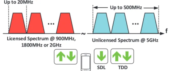
With the proliferation of mobile devices and diverse mobile applications, wireless operators are experiencing phenomenal mobile data growth around the world. It is expected that by the year 2020, the industry need to be prepared for as much as1000 times mobile traffic as the year 2010 [68]. In the upcoming 5G era, both the industry and academia are on the hunt for advanced solutions to boost the network capacity. The current available bandwidth in the licensed spectrum cannot afford the explosive mobile data demand, and excavating more capacity from other spectrum becomes indispensable. Thanks to the technique of CA, the reach of cellular systems could be extended from licensed-only operations to the unlicensed spectrum which can provide much more bandwidth. The technology which ag-gregates the licensed spectrum with the unlicensed spectrum for RRM leveraging the CA technique is named as LTE-Unlicensed (LTE-U) technology. An illustration of LTE-U ratio-nales is showed in Fig. 2.1.
... ... ~ Up to 500MHz Up to 20MHz Licensed Spectrum @ 900MHz, 1800MHz or 2GHz Unlicensed Spectrum @ 5GHz f SDL TDD
Figure 2.1. Deployment scenarios of LTE-U technology.
tech-2.4. CA in Aggregating Licensed and Unlicensed Spectrum
nology is more suitable for a small area. Hence, the deployment of most interest is operator-deployed small cell which provides access to both licensed and unlicensed spectrum for indoor environment or outdoor hotspots. The aggregation of licensed and unlicensed spec-trum can provide the small cell users with high-speed and seamless broadband multimedia services. During transmission, a licensed carrier, serving as Primary Component Carrier (PCC), and several unlicensed carriers, serving as Secondary Component Carriers (SCCs), are accessible to one user at one time. According to the user traffic demand and cell load, configuration information can be conveyed via PCC to dynamically remove/add SCCs.
There are two operation modes for LTE-U [70]: supplemental downlink (SDL) and time division duplex (TDD), as shown in Fig. 2.1. SDL mode is the simplest form of LTE-U where the unlicensed spectrum is only used for downlink data transmission since downlink traffic is typically much heavier than uplink traffic. In this mode, LTE eNB can perform most of the required operations for reliable communications, including detecting the unlicensed channel occupancy. In TDD mode, the unlicensed spectrum is used for both downlink and uplink, just like the LTE TDD system in licensed bands. TDD mode offers the flexibility to adjust the resources allocation between downlink and uplink, at the cost of extra implemen-tation complexity on the user side.
Transmission on unlicensed spectrum is unstable since the “unlicensed” nature makes it hard for provisioning guaranteed QoS. To ensure the QoS and improve the user experience, the use of unlicensed spectrum in LTE-U must come with the use of licensed spectrum. With CA, the control-plane messages including radio resource control signallings and Layer-1 sig-nallings, are always transmitted on the licensed band, where QoS is ensured. The user-plane data can be transmitted on either licensed or unlicensed carriers. In this fashion, the crucial information can always be transmitted with QoS guarantee while the unlicensed carriers can provide opportunistic best-effort data transmission enhancements.
Unlike licensed spectrum which is exclusive for the licensed users, unlicensed spectrum is usually shared by multiple unlicensed systems. Therefore, the foremost issue in unli-censed network is to achieve friendly co-existence among multiple unliunli-censed systems. For
instance, the most successful unlicensed network, Wi-Fi, uses a “listen before talk” (LBT) based MAC protocol, namely, carrier sensing multiple access with collision avoidance (CS-MA/CA), to ensure long-term fairness among different users. Thus, to implement LTE-U, it is essential for LTE-U to co-exist in a fair manner with other unlicensed networks especial-ly Wi-Fi. However, LTE and Wi-Fi adopt different MAC protocols that are fundamentalespecial-ly different, i.e., LTE uses scheduling-based MAC for synchronous transmissions while Wi-Fi implements contention-based MAC for asynchronous transmissions. How to allow efficient and friendly co-existence between synchronous LTE-U and asynchronous Wi-Fi and how to analyze the performance of each co-existing network still remain open and beckon for further investigation.
There are several MAC proposals for LTE-U in the literature. In [71] [72], an on/off transmission cycle is introduced where the on period is used for LTE-U transmissions and the off period for Wi-Fi transmissions. The off duration can be randomly selected [71] or dynamically adjusted according to the collected statistics of Wi-Fi activities [72]. For these mechanisms, the LTE-U transmission is not hinged on the instantaneous channel availability and thus may interrupt the ongoing Wi-Fi transmissions. To improve the co-existence per-formance, the LBT feature is introduced in the MAC design of LTE-U such that the LTE-U node can transmit only if the channel is sensed idle for a certain duration [73] [74]. In [73], an LTE-U node can transmit for a maximum time ratio in one cycle if the channel is sensed idle; or keep silent for the whole cycle, otherwise. An analytical performance study of the duty cycle based protocol is provided in [74]. With a duty cycle based mechanism, LTE-U senses the channel at the specific time in each duty cycle, which makes it difficult for LTE-U to retrieve the channel access due to the elastic feature of Wi-Fi transmissions. Therefore, it is hard to ensure the coexistence performance of the LTE-U system. As such, it is desirable to design a more fair MAC protocol to achieve high performance of LTE-U while ensuring a certain level of Wi-Fi protection.
Our research works [75,76] aim to tackle the above problems by designing a MAC proto-col for LTE-U small cells considering both the Wi-Fi protection and LTE channel retrieving.
2.5. Dissertation Objectives
The protocol design captures the asynchronous feature of Wi-Fi transmissions in a time-slotted MAC frame structure of LTE, and provides tunable parameters that can adjusted according to the throughput requirements of both systems and the desired Wi-Fi protection level. In addition, analytical analysis is also presented to essentially reveal the relationship among different configurable parameters.
2.5
Dissertation Objectives
Based on introduced research topics, challenges and related works, our research logic path on RRM in CA-based LTE-A systems is illustrated in Fig. 2.2.
CA in RRM of single-tier LTE-A
Downlink Uplink
Cross-CC load balancing and packet scheduling
Optimal CC configuration
Optimal CC configuration
Power control, Power offset effects
Dynamic CC (de)activation Metrics 1. Average cell/user/cell- edge throughput 2. Spectrum utilization 3. User fairness Metrics 1. Average cell/user/cell edge throughput 2. Energy efficiency and power saving CA in RRM of multi-tier HetNets Interference Modeling Metrics 1. Inter-macro-cell interference 2. Average cell/user/cell- edge throughput CA in licensed/unlicensed spectrum aggregation
Partial spectrum reuse
Inter-cell interference coordination Inter-tier Interaction
Metrics
1. Average cell throughput 2. Wi-Fi protection level Benefit demonstration of CA System limiting capabilities Metrics 1. User accommodation capabilities 2. Spectrum utilization Coexistence Protocol Design Protocol Analysis
Figure 2.2. Research path of the dissertation on RRM in CA-based LTE-A systems.
The fundamental objective of our research is to fully explore the benefits of CA in the RRM of LTE-A systems. The research starts with the benefit demonstration of CA. Instead of user-centric perspective, we choose the system-centric perspective as the study object. The system user-accommodation capabilities is investigated, i.e., the maximum number of users that can be admitted into the system given the user QoS requirements and traffic descriptors. The LTE users with CA capabilities and the legacy LTE users without the CA capabilities are compared. We would like to know how much performance gain there is in the case when all the users are LTE-A users over that when all the users are LTE ones under different parameter
configuration, and what is the intrinsic reason that results in the performance gain.
After knowing the benefits of CA, we take one step further to study how to take advantage of CA to improve the system performance in single-tier LTE-A system. We focus on the uplink CA since uplink transmissions have more limitations and the downside of CA is non-negligible. We examine the uplink CC selection and power control problems and propose a cross-layer dynamic CC selection and power control strategy with considering the power offset effects.
As the future cellular network will be a heterogeneous networks with different kinds of cells co-existing together, we extend the single-tier CA study to multi-tier CA study, where the interference management between macrocells and small cells and among small cell themselves becomes the theme. As aforementioned, CA enables the partial spectrum usage on the CC resolution. Thus in this step, we study the two-tier HetNets where MCells and FCells share the spectrum in a PSU manner. We model the co-tier and cross-tier interference exploiting the stochastic geometry capturing the locational and temporal randomness of the FCells. As MCells can only influence the FCells indirectly, we model their interaction into Stackelberg game and propose a method to obtain the equilibrium.
Finally, all the above works are considered within the licensed spectrum where the cel-lular systems have dedicated access to the spectrum resources. CA enables the spectrum aggregation between licensed and unlicensed spectrum. In this way, the system capacity can be significantly increased; meanwhile the system can operate within a unified network struc-ture on both spectrums. Our research focus on how to design the MAC protocol for LTE-U BSs in order to achieve harmony coexistence with other unlicensed systems especially the Wi-Fi systems. The proposed MAC protocol provides tunable coexistence performance with considering the essentially different PHY/MAC specifications between LTE and Wi-Fi.
2.6. Summary
2.6
Summary
In this chapter, we describe the research topics related to RRM in LTE-A systems with CA. The challenges and related works are also elaborated. Based on the research topics, the research objectives of the dissertation are further outlined. In the next few chapters, we will present our research works on each of the aforementioned topics.