Codifying Architecture Knowledge to Support
Online Evolution of Software Product Lines
Danny Weyns and Bartosz Michalik
DistriNet Labs, Katholieke Universiteit Leuven Celestijnenlaan 200A, 3001 Leuven Belgium
{danny.weyns,bartosz.michalik}@cs.kuleuven.be
ABSTRACT
A company’s architecture knowledge is often personalized across specific people that share experience and knowledge in the field. However, this knowledge may be important for other stakeholders. Omitting the codification of the architecture knowledge may result in ad-hoc practices, which is particularly relevant for software evo-lution. In a collaboration with Egemin, an industrial manufacturer of logistic systems, we faced the problem with a lack of codified architecture knowledge in the context of the evolution of a software product line (SPL). In particular, maintainers lack the architecture knowledge that is needed to perform the evolution tasks of deployed products correctly and efficiently. Ad-hoc updates increase costs and harm the company’s reputation. To address this problem, we developed an automated approach for evolving deployed systems of a SPL. Central in this approach are (1) a meta-model that codifies the architecture knowledge required to support evolution of a SPL, and (2) and algorithm that uses the architecture knowledge harvested from a deployed system based on the meta-model to generate the list of tasks maintainers have to perform to evolve the system. Evalua-tion of the approach demonstrates a significant improvement of the quality of system updates with respect to the correct execution of updates and the availability of services during the updates.
Categories and Subject Descriptors
D.2.7 [Software Engineering]: Maintenance
General Terms
on-line, evolution, SPL, software produt line
Keywords
Architecture knowledge, software produt line, evolution
1.
INTRODUCTION
Maintaining architecture knowledge in the face of system evo-lution is a difficult task [5]. A company’s knowledge manage-ment strategy captures which architecture knowledge iscodifiedin explicit accessible models, and which knowledge ispersonalized
across specific people that share their experience and knowledge in the field [4]. However, personalized architecture knowledge may
Permission to make digital or hard copies of all or part of this work for personal or classroom use is granted without fee provided that copies are not made or distributed for profit or commercial advantage and that copies bear this notice and the full citation on the first page. To copy otherwise, to republish, to post on servers or to redistribute to lists, requires prior specific permission and/or a fee.
SHARK’11, May 24, 2011, Waikiki, Honolulu, HI, USA Copyright 2011 ACM 978-1-4503-0596-9/11/05 ...$10.00.
be important for other stakeholders. Omitting the codification of this architecture knowledge may result in ad-hoc practices. Lack-ing of important architecture knowledge is particularly relevant for maintainers that have to deal with software evolution. The prob-lem may be even harder in the context of a Software Product Line (SPL). A SPL comprises a set of software systems (products) that share a common, managed set of features [7]. Stakeholders of SPL are faced not only with the evolution over time, but also with the existence of different products at the same time [15].
In a recent R&D project in collaboration with Egemin1, an in-dustrial manufacturer of logistic systems, we faced the problem with a lack of codified architecture knowledge in the context of the evolution of a SPL of logistic systems. Logistic systems in-clude a warehouse management system and control software for one or more transportation subsystems, such as automated guided vehi-cles, cranes, and conveyors. During their lifespan, logistic systems obviously have to evolve. Our particular focus of evolution is on the execution of the concrete update tasks maintainers have to per-form to evolve deployed systems. E.g., the software of a subsystem needs to be upgraded to improve performance, or a customer intro-duces a new conveyor belt and its control software needs to be inte-grated with the existing logistic system. Architects and maintainers at Egemin face various problems with such evolution scenarios.
Most of the architecture knowledge of Egemin’s SPL is person-alized across a small group of people. In addition, the logistic sys-tems comprise a lot of legacy software components, which docu-mentation is often incomplete or outdated. As a result, maintainers lack the architecture knowledge that is needed to perform the evo-lution tasks efficiently and correctly. Faulty updates increase main-tenance costs, harm the company’s reputation, or even worse, they may cause serious damage to industrial installations.
To address this problem, we developed an automated approach for evolving deployed systems of a SPL. Central in this approach are (1) an architecture meta-model that codifies the architecture knowledge required to to support evolution of a SPL, and (2) and algorithm that uses the architecture knowledge harvested from a deployed system based on the meta-model to generate the list of tasks maintainers have to perform to evolve the system. Note that we consider a spe-cific form of architecture knowledge in this paper which includes knowledge about the course grained structures of SPL products and their deployment, inconsistencies of installed products, and the up-date tasks required to evolve a deployed product. We developed a supporting tool to assist maintainers with the evolution tasks of deployed systems. Evaluation of the approach demonstrates a sig-nificant improvement of quality of system updates with respect to correctness and availability of services during the updates.
The reminder of this paper is structured as follows. Section 2 explains the problems with architecture knowledge of Egemin SPL evolution in more detail. In Section 3, we present the meta-model 1http://www.egemin.com/
L P E 'c a r S e rv ic e C lie n t/S e rv ic e v e rs io n v x v 1 0 K e y W M S C lie n t E 'tric c C lie n t E 'c a r C lie n t L o g is tic p la tfo rm v e rs io n v y L P E 'w m s S e rv ic e L P E 'w m s C lie n t W M S C lie n t L P E 'tric c S e rv ic e v 5 v 4 v 5 v 1 2 v 5 v 5 v 1 0 v 4 v 1 2 H o s t 1 H o s t 2 H o s t 3 H o s t 4 H o s t v x v y
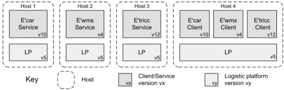
Figure 1: Typical configuration of a logistic system
that codifies the architecture knowledge required to support evolu-tion of a SPL. Secevolu-tion 4, the central part of the paper, explains in detail the algorithm that uses the harvested knowledge based on the meta-model to generate the list of tasks a maintainer has to perform to evolve a deployed system. In Section 5, we briefly report on the evaluation of the approach. Finally, we present related work in Sec-tion 6, and draw conclusions in SecSec-tion 7.
2.
PROBLEMS WITH SPL EVOLUTION
Figure 1 shows a typical configuration of a logistic system. The system includes a warehouse management system (E’wmsR -Egemin warehouse management system) that is responsible for managing tasks in the system, and control software for automated guided vehicles (E’triccR - Egemin transport intelligent control center) and cranes (E’carR - Egemin crane automatic storage and retrieval system). These logistic subsystems are built from a com-mon set of components that can be customized and composed to the needs of the customers. The software is deployed on four hosts. Each logistic subsystem comprises a service and a client that makes use of the distributed logistic platform. The service offers the func-tionality of the subsystem, whereas the client offers a graphical in-terface to access the service. The distributed logistic platform is a component framework developed by Egemin that provides common middleware services for logistic systems such as support for system configuration, communication, persistence, online updates, etc.
Egemin’s SPL comprises over 200 deployed logistic systems. During their lifespan (typically 10+ years), logistic systems obvi-ously have to evolve. An example of an evolution scenario for the configuration shown in Figure 1 could be an upgrade the E’car ser-vice from versionv10to versionv12which includes a new stacking algorithm that reduces the average retrieval time by 12%.
The goal of a system evolution is to migrate the deployed logistic system (as-is) to a new version (to-be). The new version is avail-able as a set of installation bundles that comprise all the resources (e.g. executables or libraries) of the updated system together with a specification of the target location of each resource. Two important requirements that have to be satisfied during system evolution are:
R1. Correctness: The maintainer should perform a correct sequence of update steps to bring the system from the as-is to the to-be version. Update steps include adding/removing/replacing resources and stopping/starting processes. Restarting an incorrect configuration may com-promise the consistency of the logistic system.
R2. Availability: The maintainer should minimize the total shut-down time of the various logistic subsystems. Logistic sys-tems typically have to operate 24/7. Interruption of its ser-vices is costly and should be kept minimal.
To perform an update, maintainers need detailed knowledge of the deployed system and the installation bundles. Required knowl-edge of the deployed system includes the set of running subsystems
each with its resources, the location and version of each resource, the dependencies between resources, the set of running processes, etc. Required knowledge of the installation bundles include the set of subsystems that have to be deployed after the update each with its resources, the target location and version of each resource, the de-pendencies between resources, the set of processes that have to run after the update, etc. Based on this knowledge, a correct sequence of update steps have to be derived that ensure a correct update of the deployed system with minimal interruption of its services.
Unfortunately, this detailed knowledge is not codified in explicit models. Since different subsystems are developed by different teams in the company, the personalized knowledge is spread across a num-ber of people. Moreover, the deployed logistic systems comprise a lot of legacy software components for which documentation is often incomplete or outdated. The lack of documentation and detailed ar-chitecture knowledge leads to the ad-hoc update practices which are inefficient and error prone.
Together with the architects and maintainers at Egemin, we iden-tified three models that codify the architecture knowledge required to evolve deployed logistic systems (products) of the SPL:
M1 As-Is Product Deployment Model: A model of the current product that shows locations, deployed subsystems with their resources, resource dependencies, and the running processes.
M2 To-Be Product Deployment Model:A model of the future ver-sion of the product which is available as a set of installation bundles. This model shows the target set of subsystems with their resources, target locations of the resources, resource de-pendencies, and processes that have to run after the update.
M3 Update Procedure Model: A model that describes the se-quence of update steps (resource changes and process manip-ulations) that need to be performed to evolve the deployed logistic system from the as-is to the to-be version.
In summary, the problem we have to solve is: (1) to codify the architecture knowledge of models M1 and M2, (2) to codify the ar-chitecture knowledge of model M3 by analyzing models M1 and M2, and (3) to develop support for automatic reconstruction of this knowledge for a particular evolution setting to enable maintainers to evolve deployed systems. The focus of this paper is on the codifica-tion of the architecture knowledge, i.e. subproblems (1) and (2).
3.
META-MODEL
A meta-model presents the conceptual entities, their attributes and the relationships that comprise the vocabulary of a type of model [14]. We use meta-models to codify the architecture knowl-edge required to evolve deployed SPL products. We follow a bottom up approach which reflects the way we defined the models in prac-tice. We start by introducing as-is and to-be product deployment meta-models for Egemin’s logistic systems. Then we integrate these models in a single meta-model. This first set of models was de-fined in close interaction with the key stakeholders at Egemin. The
model concepts are specific to the company’s technological context (.NET). Next, we generalize the integrated meta-model based on a thorough literature study, including [2, 3, 15, 18]. The generalized meta-model offers reusable architecture knowledge to support the evolution of deployed SPL products, independently of any partic-ular technology. The section concludes with a brief note on the a supporting framework we developed to support harvesting of archi-tecture knowledge based on the integrated meta-model.
3.1
As-Is Product Deployment Meta-Model
Figure 2 shows the as-is product deployment meta-model. This meta-model codifies the architecture knowledge ofdeployed logis-tic systemsof Egemin’s SPL (as-is products) required to perform updates. H o s t A s s e m b ly A s s e m b ly D e p e n d e n c y v e rs io n v e rs io n E X E F ile 0 ..1 * 1 ..* re fe rs to h a s * 1 1 * c o rre s p o n d s to is d e p lo y a b le o n 1 ..* * is d e p lo y e d o n c o n s is ts o f 1 ..* * W in d o w s P ro c e s s ru n s o n * 1 0 ..1 1 s ta rts u s e s 1 ..* * h a s * * * * * E g e m in S P L c o n ta in s D L L F ile L o g is tic S y s te m in v o lv e s L o g is tic S u b s y s te m S u b s y s te m C o n s tra in t 1 1 ..* v e rs io n v e rs io n
Figure 2: As-is product deployment meta-model
Egemin’s SPLcontains a set oflogistic systems. A logistic sys-tem consists oflogistic subsystems, such as management systems and control software for automated guided vehicles. Both, logis-tic systems and subsystems have aversion. Logistic systems may haveconstraintsto each other that put restrictions on their compo-sition. For example, the combination of E’tricc and E’can requires the installation of E’wms, or a particular version of E’tricc excludes a particular version E’can. A logistic subsystem is deployed on a set ofhosts. Each host contains a set ofassembliesthat correspond to particular logistic subsystems. An assembly has a version. Assem-blies includeEXE files(Executable) andDLL files(Dynamic Link Library). An assembly may havedependenciesto other assemblies. A deployed executable assembly can be started as aprocessthat runs on a host. A process uses one or more assemblies.
3.2
To-Be Product Deployment Meta-Model
Figure 3 shows the to-be product deployment meta-model. This meta-model codifies the architecture knowledge of Egemin’sfuture logistic systems(to-be products) that is needed to perform updates.
A future logistic system can be deployed with a set ofMSI Files
(Microsoft Installer). An MSI file contains deployable assemblies that correspond to logistic systems and can be installed on hosts.
3.3
Integrated Meta-Model
Figure 4 shows the integrated product deployment meta-model that fuses the as-is and to-be product deployment meta-models.
The integrated meta-model offers the basis for an architectural repository that can be populated with the necessary architecture knowledge for a particular setting by harvesting the knowledge from the deployed system and the installation bundles. The harvested
M S I F ile A s s e m b ly A s s e m b ly D e p e n d e n c y v e rs io n * re fe rs to h a s * 1 1 * c o rre s p o n d s to * 0 ..1 1 ..* * c o n ta in s d e p lo y a b le c a n b e d e p lo y e d w ith H o s t h a s to b e d e p lo y e d o n * * 1 ..* c o rre s p o n d s to E X E F ile D L L F ile v e rs io n c o n s is ts o f 1 ..* * h a s * * * * E g e m in S P L c o n ta in s L o g is tic S y s te m in v o lv e s L o g is tic S u b s y s te m S u b s y s te m C o n s tra in t 1 1 ..* v e rs io n v e rs io n *
Figure 3: To-be product deployment meta-model
H o s t M S I F ile A s s e m b ly A s s e m b ly D e p e n d e n c y v e rs io n D L L F ile E X E F ile 0 ..1 * * * h a s to b e in s ta lle d o n re fe rs to h a s * 1 1 * c o rre s p o n d s to is d e p lo y a b le o n * * 0 ..1 1 ..* 1 ..* * * c o n ta in s d e p lo y a b le is d e p lo y e d o n c a n b e d e p lo y e d w ith W in d o w s P ro c e s s ru n s o n * 1 0 ..1 1 s ta rts u s e s 1 ..* * v e rs io n 1 ..* c o n s is ts o f 1 ..* * h a s * * * * E g e m in S P L c o n ta in s L o g is tic S y s te m in v o lv e s L o g is tic S u b s y s te m S u b s y s te m C o n s tra in t 1 1 ..* v e rs io n v e rs io n
Figure 4: Integrated product deployment meta-model
knowledge is then used to derive the update procedure model that defines the sequence of update steps the maintainer has to perform to evolve the system from as-is to to-be. We explain the algorithm to determine the update steps in section 4.
3.4
Generalized Meta-Model
Figure 5 shows the generalized product deployment meta-model. The generalized meta-model specifies the conceptual entities and their relationships that codify the architecture knowledge required to evolve deployed products of a SPL, independently of any particular technology. The mapping between the concepts of the generalized meta-model and the concepts of Egemin’s SPL are summarized in the following table.
General Meta-Model Concepts Egemin Meta-Model Concepts Product Logistic System Asset Base Egemin’s asset Base
Asset Logistic Subsystem Asset Constraint Subsystem Constraint
Location Host
Installation Bundle MSI File Resource Assembly (EXE, DLL File) Resource Dependency Assembly Dependency
Process Windows Process
meta-L o c a tio n In s ta lla tio n B u n d le R e s o u rc e R e s o u rc e D e p e n d e n c y v e rs io n D a ta b a s e C o n fig file A s s e m b ly 0 ..1 * * * h a s to b e in s ta lle d o n re fe rs to h a s * 1 1 * c o rre s p o n d s to is d e p lo y a b le o n * * 0 ..1 1 ..* 1 ..* * * c o n ta in s d e p lo y a b le is d e p lo y e d o n c a n b e d e p lo y e d w ith P ro c e s s ru n s o n * 1 0 ..1 1 s ta rts u s e s 1 ..* * 1 ..*v e rs io n c o n s is ts o f 1 ..* * h a s * * * * S P L c o n ta in s P ro d u c t in v o lv e s A s s e t A s s e t C o n s tra in t 1 1 ..* v e rs io n v e rs io n
Figure 5: Generalized product deployment meta-model
model for the specification of the algorithm to generate the update steps to evolve a product of a SPL.
3.5
Supporting Framework
Figure 6 shows the primary components of the framework that we developed to support online evolution of SPL.
G U I W o rk flo w C o n tro lle r
R u n tim e C o m p o n e n ts , C o n fig u ra tio n F ile s ,
D e p lo y a b le A s s e m b lie s , e tc . R e q u ire dIn te rfa c e P ro v id e dIn te rfa c e
C o m p o n e n t K E Y R e p o s ito ry A rc h ite c tu re K n o w le d g e C o lle c to r A rc h ite c tu re K n o w le d g e R e p o s ito ry M o d e l B u ild e r C o lle c ts D a ta F ro m
Figure 6: General overview of the supporting framework
System maintainers interact through a standardGUI(Graphical User Interface) to harvest architecture knowledge, build models (as-is, to-be, and update procedure model), and browse the models. The
workflow controllertriggers the architecture knowledge collector,
architecture knowledge repository, and themodel builderto execute these actions.
The architecture knowledge collector comprises a number of pluggable harvester components that perform the actual knowledge gathering. Knowledge can be extracted from run-time system com-ponents, resource files, system configurations, etc. Three example harvesters that we used to harvest knowledge for Egemin’s SPL are:
• Assembly Harvester: gathers knowledge about the the semblies of the deployed system per location, including as-sembles’ version and compile time dependencies. This har-vester includes a C# program based on the Mono.Cecil li-brary (http://www.mono-project.com/Cecil) that supports in-spection of programs and libraries.
• Config File Harvester: gathers configuration knowledge about dynamically loaded assemblies and the run-time dependen-cies between assemblies. Two examples of configuration files
harvested this way are the .Net App.config file and the Pro-fileCatalog.xml for SmartClients in .Net.
• MSI files Harvester: gathers knowledge about the to-be de-ployed product. This harvester uses the two previous har-vesters to collect knowledge of the assemblies from a MSI file, including versions and dependencies.
The architecture knowledge collected by the harvesters is used to populate the architecture repository. The repository stores archi-tecture knowledge that complies to the integrated meta-model dis-cussed above. We used the Eclipse Modeling Framework (EMF) as a basis for the repository. EMF supports specifying a meta-model, and generating a Java implementation along with set of adapter classes that enable basic viewing and command-based editing.
Finally, the model builder queries the architecture repository to generate on demand the architecture models requested by the main-tainer. The as-is deployment model (M1) and to-be deployment models (M2) can directly be derived from the knowledge stored in the repository. The update procedure model (M3) requires further analysis of the stored knowledge. We discuss the algorithm to gen-erate the update procedure model in the next section.
4.
UPDATE PROCEDURE MODEL
We now discuss in the algorithm to generate the updated proce-dure model in detail. This model is derived from the analysis of the knowledge harvested from a deployed system and the installation bundles. The update procedure model lists a sequence of steps that maintainers have to perform to evolve a system correctly and with minimal interruption of its services. The algorithm is based on the assumption that the system under evolution allows online updates, This requires support for (de-)activation of components, buffering of messages, etc. Egemin’s logistic platform offers such support (see section 2).
This section starts with a high-level overview of the algorithm and a description of a running example. Next, a number of defini-tions are introduced that will be used in the algorithm. Then, the algorithm is discussed in detail and illustrated with excerpts of the running example.
4.1
Overview Algorithm
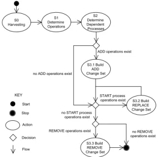
Figure 7 shows an overview of the algorithm to generate the up-date procedure model.
S 2 D e te rm in e D e p e n d e n t P ro c e s s e s S 3 .1 B u ild A D D C h a n g e S e t S 3 .2 B u ild R E P L A C E C h a n g e S e t S 3 .3 B u ild R E M O V E C h a n g e S e t S ta rt S to p A c tio n D e c is io n F lo w n o R E M O V E o p e ra tio n s e x is t R E M O V E o p e ra tio n s e x is t S T A R T p ro c e s s o p e ra tio n s e x is t n o S T A R T p ro c e s s o p e ra tio n s e x is t A D D o p e ra tio n s e x is t n o A D D o p e ra tio n s e x is t K E Y S 1 D e te rm in e O p e ra tio n s S 0 H a rv e s tin g
The algorithm consists of three main steps (S1 - S3). Step S0 is a preparatory step in which the architecture knowledge is harvested from the deployed system and the installation bundles and stored in the architecture repository.
In the first step, S1, the resource operations are determined (ADD, REPLACE, REMOVE). The set of operations is derived from a comparison of the architecture knowledge of the as-is and to-be sys-tem. For example, if there is a resource in the to-be system that is not in the as-is, a new ADD operation is defined for this resource. In the second step, S2, all the STOP and START operations for pro-cesses are determined. The set of affected propro-cesses consists of all the processes with a direct or indirect dependency on a resource for which a REMOVE or REPLACE operation exists.
In the third step, S3, all the operations are ordered to ensure that the shutdown time of the system services is minimized. S3 con-sists of three sub-steps: S3.1 to S3.3. In each sub-step a particular
change setis computed. A change set consists of a sequence of update operations that migrate the system from one consistent state to another. In step S3.1, the change set of ADD operations is deter-mined. The ADD operations can be executed without shutting down any part of the deployed system. Next, in step S3.2, the change sets with REPLACE operations are determined. Each change set con-sists of the subset of REPLACE operations that are applicable to a set of resources that have dependencies with one another. The RE-PLACE operations will be preceded by STOP operations and end with START operations for all processes with dependencies to any of the resources involved in the change set. The services associated with the interrupted processes are not available during the execution of the REPLACE change sets. Finally, in step S3.3, the change set of REMOVE operations is determined. The REMOVE operations will be preceded by STOP operations for all processes that have to be terminated, i.e. the processes with dependencies to any of the re-sources involved in the change set. As such, REPLACE operations do not require a shutdown of active services of the deployed system.
4.2
Running Example
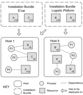
We will illustrate the different steps of the algorithm with a sim-plified evolution scenario of the logistic system shown in Figure 1 of Section 2. The initial setting of the scenario is shown Figure 8.
The figure shows the resources and processes with their depen-dencies deployed on two locations of the system. In reality, several hundreds of resources are deployed on each host of a logistic sys-tem. The installation bundles with the resources of a new version of E’car and the logistic platform are also shown. The arrows indicate on which locations the installation bundles have to be deployed.
4.3
Definitions
Before we explain the algorithm in detail, we first give a number of definitions.
Type Definitions
The basic types for resources, processes, dependencies etc. are de-rived from the generalized product deployment meta-model shown in Figure 5 of Section 3. Due to space constraints, we omit the formal specification of these types. In addition, we introduce the
Operationtype that defines atomic steps of the update procedure. We define a specialized operation for each kind of update step:
ADD(r : Resource, l: Location)
Adds resourcerto locationl.
REMOVE(r: Resource, l : Location)
Removes resourcerfrom locationl.
REPLACE(ro, rn : Resource, l : Location) Replaces resourcerowith resourcernat locationl.
STOP(p : Process, l : Location)
Stops processpat locationl.
P 1 P 2 P 3 B v 5 C v 9 A v 1 2 H o s t 1 P 1 P 3 B v 5 E v 5 D v 9 H o s t 4 A v 1 2 Cv 1 2 Bv 1 0 Dv 9 In s ta lla tio n B u n d le E 'c a r In s ta lla tio n B u n d le L o g is tic P la fo rm H o s t In s ta lla tio n B u n d le P ro c e s s R e s o u rc e D e p e n d e n c y H a s to b e d e p lo y e d o n K E Y P 2
Figure 8: Example scenario to illustrate the update procedure
START(p : Process, l : Location)
Starts processpat locationl.
The result of the algorithm is the update procedure model that we represent as an update script:
updateScript : Operation[]
The square brackets define a sequence, in this case a sequence of operations. We use{}to define a regular set.
Input Functions
The harvested knowledge stored in the architecture repository is used as input for the algorithm. We introduce the following func-tions to access this knowledge:
locations() : Location{}
Returns the set of locations on which the logistic system is deployed.
resourcesas−is(l : Location) : Resource{} Returns the set of deployed resources for the given location.
resourcesto−be(l : Location) : Resource{} Returns the set of resources of an installation bundle that have to be deployed on the given location.
processes(l : Location) : Process{}
Returns a set of processes running at the given location.
lockedBy(l: Location, r: Resource,p: Process): bool
Evaluatestruewhen processpis using resourcerat location
l, and false otherwise.
Helper functions
The following helper functions are defined to simplify the descrip-tion of the algorithm:
getOperations(rs: Resource{}, os: Operation{}): Operation{}
Selects all the operations from the setosthat are defined on resources from the setrs.
getResources(os: Operation{}, l : Location): Resources{}
Selects all the resources deployed to locationlfor which an operation in the setosis defined.
append(operations: Operation[], o : Operation)
Appends operationoto the given sequence ofoperations.
4.4
Algorithm
We now give a detailed description of the subsequent steps of the algorithm to generate the update procedure model. Unless stated differently, all sets and sequences are initialized as empty. Due to space constraints, some parts of the algorithm are omitted. The com-plete algorithm specification is available for the interested reader2.
Step 1. Determine Resource Operations
Initialization:
1:toAdd:Resource{} 2:toRemove:Resource{}
3:radd:Resource Procedure:
4:for alll∈locationsdo
5: toRemove←
6: {r:r∈resourcesas−is(l)∧r6∈resourcesto−be(l)}
7: toAdd← {r:r∈resourcesto−be[l]∧r6∈resourcesas−is(l)}
8: for allr∈toRemovedo
9: radd←x:x∈toAdd∧r.name=x.name
10: ifradd6=nilthen
11: operationsrep[l]←
12: operationsrep[l]S{REP LACE(r, radd, l)}
13: toAdd←toAdd\ {radd}
14: else
15: operations[l]rem←
16: operations[l]remS{REM OV E(r, l)}
17: end if
18: end for
19: for allr∈toAdddo
20: operations[l]add←operations[l]addS{ADD(r, l)}
21: end for
22:end for
Listing 1: Determining the resource operations.
The resource operations are derived from the comparison of the sets of resources of the deployed system (as-is resource set) and the installation bundles (to-be resource set) for each location. Lines
5,6define thetoRemoveset. This set contains all the resources that are currently deployed, but are not present in the installation bundles. Line7defines thetoAddset. This set contains all the resources which are present in the installation bundles and are not deployed yet.
The remainder of the procedure defines the proper resource oper-ations based on thetoRemoveandtoAddsets. Line 9 checks for each element of thetoRemoveset whether it also belongs to the
toAddset. If the element belongs to both sets, aREPLACE oper-ation is added to the set of replace operoper-ations for the correspond-ing resource, and the element is removed from thetoAddset (lines
11-13). Otherwise, aREMOVEoperation is added to the set of re-move operations (lines15-16). Finally, for all remaining elements in thetoAddset, anADDoperation is added to the set of add opera-tions (lines19-21). OU T P U T: Host 1: REPLACE(Bv5,Bv10,H1), REPLACE(Cv9,Cv12,H1), ADD(Dv9,H1). Host 4: REPLACE(Bv5,Bv10,H4), REMOVE(Ev5,H4)
Listing 2: Resource operations for the running example
The result of step 1 for the running example is shown in Listing 2. There are twoREPLACEoperations and oneADDoperations defined 2http://people.cs.kuleuven.be/danny.weyns/UpdateModelAlgorithm.pdf
for Host 1. In addition, oneREPLACEand oneREMOVEoperation is defined for Host 4.
Step 2. Determine Dependent Processes
To ensure consistency, every running process of the deployed sys-tem that uses a resource with aREPLACEor REMOVEoperation has to be shutdown during the execution of these operations. The algorithm defines two sets of dependent processes: processesrst contains all processes that depend on at least one resource in the
REPLACEoperation set, andprocessesstpcontains all processes that depend on at least one resource in theREMOVEoperation set. Due to space constrains, we omit the specification of this part of the algorithm. IN P U T: Locked at Host 1: (P1 : Bv5, Cv9), (P2 : Cv9), (P3 : Av12) Locked at Host 4: (P1 : Bv5), (P2 : Bv5, Dv9), (P3 : Ev5) OU T P U T: processesrst[Host 1] : P1,P2 processesrst[Host 4] : P1,P2 processesstp[Host 4] : P3
Listing 3: Dependent processes for the running example.
Listing 3 shows the resource dependencies of the processes for the running example. All the processes with a dependency to a resource with anREPLACEoperation are added to theprocessesrstsets for both hosts. Process P3 at Host 4 is added to theprocessesrstset since it has a dependency to resourceEv5which will be removed. Process P3 at Host 1 is not affected because there is no operation defined for resourceAv12at this location.
Step 3. Build Change Sets
In the last step of the algorithm, the sequence of proper update oper-ations is generated. We explain the subsequent sub-steps and illus-trate them with excerpts of the running example.
The sequence of update operations are collected in the
updateScript. First, allADDoperations are added to the update script in lines8,9. SinceADDoperations do not influence running processes no process operation need to be defined. Figure 9 shows theADDchange set for the running example which contains only the operation ADD(Dv9,H1) that is included in the update script shown in Listing 5.
Lines11-19describe the preparation stage for the composition of theREPLACEchange sets. For each resource, the number of re-place operations on different locations is determined. We assume that the names of resources can be ordered. For the running exam-ple, resources are ordered alphabetically (A. . . E). To minimize the impact of replace operations, the replace change sets will ordered in the update script according to decreasing number of affected re-sources. The result of this preparation stage for the running example is shown as the first part of Listing 5.
Next, in the lines20-53theREPLACEchange sets are gener-ated. First, the sets of affected resources and processes with depen-dencies are computed for each location (lines22-32). The compu-tation starts with the resource that needs to be replaced on a maxi-mum number of locations. In the running example, this is resource B, which has to be replaced on both hosts. At Host 1, resource B has dependencies with the local processes P1 and P2, and indirectly with resource C. At Host 2, resource B has dependencies with the local processes P1 and P2. Figure 9 shows how all these resources and processes belong to the singleREPLACEchange set.
Next, for each generatedREPLACE change set, operations are added to the update script (lines33-52). Subsequently,STOP op-erations for the processes are added, followed by theREPLACE
op-Initialization:
1:af f ected:Resource{}[|locations|] 2:rscount:N[]
3:rmax:Resource
4:rl:Resource
5:toRestart:P rocess{}[|locations|] 6:toRestart‘ :P rocess{}
7:toM odif y[l] :Resource{}[|locations|]
Procedure:
8:forl∈locationsdo
9: updateScript←operationsadd[l]
10:end for
11:forl∈locationsdo
12: af f ected[l]← {r:r∈getResources(operations[l]rep)}
13:end for 14:rscount←[]
15:forl∈locationsdo
16: forr∈af f ected[l]do
17: rscount[r.name]←rscount[r.name] + 1
18: end for
19:end for
20:whileP
l∈locations|processesrst[l]|>0do
21: rmax←r:r∈Sl∈locationsaf f ected[l]∧maxrscount[r.name]
22: for alll∈locationsdo
23: rl←r:r∈af f ected[l]∧r.name=rmax.name
24: toRestart[l]← {}
25: toRestart0← {p:p∈processesrst[l]∧lockedBy(l, rl, p)}
26: while|toRestart[l]|<|toRestart0|do
27: toRestart[l]←toRestart0
28: toM odif y[l]← {r:r∈af f ected[l]∧ ∃p∈toRestart[l] :
lockedBy(l, r, p)}
29: toRestart0←
30: {p:p∈processesrst[l]∧ ∃r∈toM odif y[l] : lockedBy(l, r, p)}
31: end while
32: end for
33: for alll∈locationsdo
34: processesrst[l]←processesrst[l]\toRestart[l]
35: processesstp[l]←processesstp[l]\toRestart[l]
36: for allp∈toRestart[l]do
37: append(updateScript, ST OP(p, l))
38: end for
39: end for
40: for alll∈locationsdo
41: for allo∈getOperations(toM odif y[l], operationsrep[l])do
42: append(updateScript, o)
43: end for
44: for allr∈toM odif y[l]do 45: rscount[r.name]←0
46: end for
47: end for
48: for alll∈locationsdo
49: for allp∈toRestart[l]do
50: append(updateScript, ST ART(p, l))
51: end for
52: end for
53:end while
54:for alll∈locationsdo
55: for allp∈processesrst[l]do
56: append(updateScript, ST OP(p, l))
57: end for
58: for allo∈operationsrem[l]do
59: append(updateScript, o)
60: end for
61:end for
Listing 4: Build update scripts.
erations for the resources, and finally,STARToperations are added for the stopped processes. The set of operations for the single
REPLACEchange set in the running example are shown in Listing 5. The sequence consists of theSTOPoperations for processes P1 and P2 at both hosts, followed by theREPLACEoperations for the various resources, and finally theSTARToperations are added.
Finally, theREMOVEchange set is generated (lines54-61) for all the resources for whichREMOVEoperations are defined. The operations are added to the update script, preceded bySTOP opera-tions for the dependent processes that are no longer needed after the update. Figure 9 shows that theREMOVEchange set comprises only
PR E P A R A T I O N S T A G E:
rscount[A] : 1 rscount[B] : 2
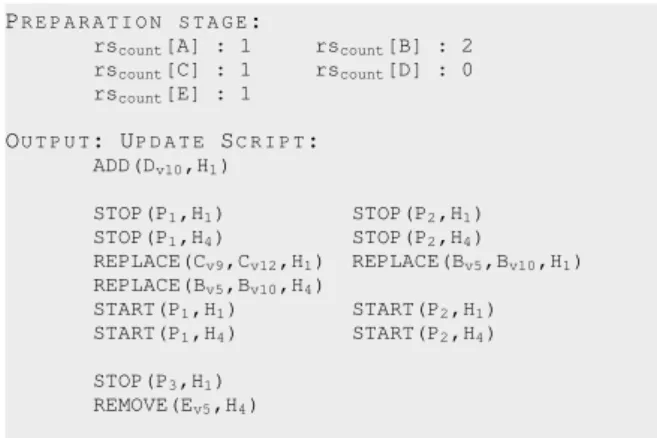
rscount[C] : 1 rscount[D] : 0 rscount[E] : 1 OU T P U T: UP D A T E SC R I P T: ADD(Dv10,H1) STOP(P1,H1) STOP(P2,H1) STOP(P1,H4) STOP(P2,H4) REPLACE(Cv9,Cv12,H1) REPLACE(Bv5,Bv10,H1) REPLACE(Bv5,Bv10,H4) START(P1,H1) START(P2,H1) START(P1,H4) START(P2,H4) STOP(P3,H1) REMOVE(Ev5,H4)
Listing 5: Update script for the running example
resource E at host 4 together with process P3. The corresponding operations conclude the update script as shown in Listing 5.
P 1 P 2 P 3 B v 5 C v 9 A v 1 2 H o s t 1 P 1 P 3 B v 5 E v 5 D v 9 H o s t 4 D v 9 H o s t P ro c e s s R e s o u rc e D e p e n d e n c y C h a n g e S e t K E Y P 2 A D D R E P L A C E R E M O V E
Figure 9: Change sets for the running example.
5.
EVALUATION
We have evaluated the approach for online evolution of SPL in an empirical study. In this paper, we briefly summarize the results of this study. A detailed report of the study is available for the in-terested reader3. We evaluated a total of 68 updates of industrial logistic systems of Egemin performed by 17 professionals, half of them with Egemin’s traditional update approach, the other half with the tool that automatically generates update scripts. We formulated hypothesis with respect to the correct execution of product evolu-tions (R1) and the availability of services during the updates (R2). Statistical analysis revealed significant differences for the tested hy-pothesis. In particular, the results demonstrate that 44% of the dates with the traditional approach contain errors, while all the up-dates with the tool were performed correctly. Furthermore, the re-sults show that with the traditional approach 58% of the process shutdowns were unnecessary, while there were only 7% redundant process shutdowns with the tool.
In addition, we probed whether the availability of architectural knowledge changed the maintainers’ attitude to evolution tasks. Therefore, we used a questionnaire that the subjects completed af-ter the update tasks. The results indicate that maintainers felt more confident that the updates were performed correctly when they use the tool with explicit update scripts. The fact that the number of sys-tem modifications was almost seven times higher in the traditional approach as with explicit update scripts confirms this finding. 3http://people.cs.kuleuven.be/danny.weyns/EmpiricalStudyOnlineUpdates.pdf
6.
RELATED WORK
In theory, the choice of an architectural knowledge management strategy should be made explicitly and tailored to the organization’s needs. However, in practice, there never seems to be enough time to document architecture knowledge with enough rigor to be useful[4]. Researches from the GRIFFIN project list a number of issues related to architecture knowledge management in a organization [11]. They report lack of consistency between documentation and the actual system, communication overhead between stakeholders, and lack of explicit collaboration between maintenance teams. Our experiences with Egemin confirm these findings.
Several authors have pointed to the complexity of managing SPL evolution. [17] argues that SPL evolution is complex process be-cause of various interdependencies between software assets. [13] points to the complexity associated with the typical mismatch be-tween architectural variability and the actual variability.
To deal with the lack of detailed architecture knowledge of SPL evolution, a number of methods and tools have been proposed. [16] proposes architecture reconstruction as a means to integrate product features in the platform and to maintain the architectural integrity of the platform. Tools such as Ménage [12] (xADL 2.0 based represen-tation), SELECTA [10] (which uses composition of meta-models) and pure::variants [6] (industrial tool) help with the recovery of architecture knowledge. Whereas the described approaches focus on evolution of the design and implementation time artifacts, we address the codification of architecture knowledge for deployment time evolution of the SPL products.
Our approach benefits from the research in the domain of software architecture reconstruction. [8] provides a general overview of the state of the art in this area. Comparing to existing approaches, we derive as-is models from heterogeneous set of information sources of the deployed products. We also extract the to-be models, i.e. the valid installation bundles of updated products.
Several methods for differenting architecture models have been proposed. [9] uses source code level differencing to analyze the variability in SPL in a reverse engineering context. [1] proposes a tree-to-tree correction algorithm for differencing and merging archi-tectural models. In our work, differencing models has a specific and practical objective. In particular, the algorithm presented in this pa-per uses harvested architecture knowledge to generate automatically the update scripts for evolving deployed products of a SPL.
7.
CONCLUSIONS AND FUTURE WORK
In a join effort with Egemin, we faced the problem with a lack of explicit architecture knowledge to evolve deployed products of a SPL correctly and efficiently. To tackle this problem, we devel-oped an automated approach to support maintainers of product lines. Together with Egemin’s key stakeholders, we codified the architec-ture knowledge required to evolve SPL in an integrated meta-model. This meta-model offers the basis for a repository that can be popu-lated with the relevant knowledge harvested from system artifacts. We also codified the architecture knowledge of the update procedure for evolving systems in an algorithm that generates the sequence of steps that maintainers have to perform to evolve a deployed system to a new version in a correct and efficient manner.
We developed a supporting tool for the approach and used it to perform a controlled experiment in which we evaluated the up-dates of 68 industrial logistic system, half of them performed with Egemin’s traditional update approach, the other half with the tool. The results give evidence that using the tool significantly improves correctness and availability of services during system evolutions. Moreover, we observed a positive change in the maintainers’ atti-tude to the evolution task, in particular with respect to their confi-dence in performing their tasks with the tool.
Architecture knowledge typically refers to design decisions,
ra-tionale, and the like. In this paper, we complement this traditional perspective with a specific form of architecture knowledge. In par-ticular, we consider knowledge about the course grained structures of SPL products, dependencies between components of products, and the update procedure to evolve deployed products.
Although we successfully applied our approach to Egemin’s SPL, several research challenges remain. First, we plan to formally proof the correctness and availability properties of the proposed approach. Second, we plan to challenge the generality of the approach by ap-plying it to a different domain with different technology. Finally, we plan to extend our work by exploring evolution scenarios in which the asset base of the SPL evolves, rather than particular products. An example scenario in Egemin’s context is the introduction of a new module that deals with timing issues of external logistic services.
8.
REFERENCES
[1] M. Abi-Antoun, J. Aldrich, N. Nahas, B. Schmerl, and D. Garlan. Differencing and merging of architectural views.
Automated Software Engineering, 15(1):35–74, 2008. [2] S. Ajila and A. Kaba. Evolution support mechanisms for
software product line process.Journal on Systems and Software, 81(10):1784–1801, 2008.
[3] N. Anquetil et al. A model-driven traceability framework for software product lines.Software & Systems Modeling, 2010. [4] P. Avgeriou, P. Kruchten, P. Lago, P. Grisham, and D. Perry.
Architectural knowledge and rationale: issues, trends, challenges.Softw. Eng. Notes, 32:41–46, July 2007. [5] M. Babar, T. Dingsyr, P. Lago, and H. van Vliet. Software
architecture knowledge management.Springer, 2009. [6] D. Beuche. Variant management with pure:: variants.
Pure-systems GmbH, Tech. Rep, 2003.
[7] P. Clements and L. Northrop.Software product lines. Addison-Wesley Reading MA, 2001.
[8] S. Ducasse and D. Pollet. Software architecture
reconstruction: A process-oriented taxonomy.IEEE Trans. on Software Engineering, 35(4):573 –591, 2009.
[9] S. Duszynski. Visualizing and Analyzing Software Variability with Bar Diagrams and Occurrence Matrices. In14th Software Product Lines Conference, SPLC, 2010. [10] J. Estublier, I. A. Dieng, and T. Leveque. Software product
line evolution: the selecta system. InProduct Line Approaches in Software Engineering. ACM, 2010. [11] R. Farenhorst, P. Lago, and H. van Vliet. Prerequisites for
successful architectural knowledge sharing. In18th
Australian Software Engineering Conference, ASWEC, 2007. [12] A. Garg et al. An environment for managing evolving product
line architectures. InSoftware Maint. Conf., 2003. [13] S. A. Hendrickson and A. van der Hoek. Modeling product
line architectures through change sets and relationships. In
International Conference on Software Engineering, 2007. [14] R. Hilliard. A trust viewpoint.Technical Report, 2009.
mysite.verizon.net/rfh2/writings/hilliard-TrustVP-r1.pdf. [15] K. Pohl, G. Böckle, and F. Van Der Linden.Software product
line engineering: foundations, principles, and techniques. Springer-Verlag New York Inc, 2005.
[16] C. Riva and C. Del Rosso. Experiences with software product family evolution. InPrinciples of Software Evolution, 2003. [17] M. Svahnberg and J. Bosch. Evolution in software product
lines: Two cases.Journal of Software Maintenance, 11(6):391–422, 1999.
[18] F. Van Der Linden, K. Schmid, and E. Rommes.Software product lines in action: the best industrial practice in product line engineering. Springer, 2007.