Standard Test Methods for
Determination of Solution Viscosities of Polyamide (PA)
1, 2 This standard is issued under the fixed designation D 789; the number immediately following the designation indicates the year of original adoption or, in the case of revision, the year of last revision. A number in parentheses indicates the year of last reapproval. A superscript epsilon (´) indicates an editorial change since the last revision or reapproval.1. Scope*
1.1 These test methods cover the determination of solution viscosities as they apply to polyamide (PA).
1.2 The values stated in SI units are to be regarded as standard. The values given in brackets are for information only. 1.3 This standard does not purport to address all of the safety concerns, if any, associated with its use. It is the responsibility of the user of this standard to establish appro-priate safety and health practices and determine the applica-bility of regulatory limitations prior to use.
NOTE 1—This standard andISO 307address the same subject, but the
technical content is different. 2. Referenced Documents
2.1 ASTM Standards:3
D 446 Specifications and Operating Instructions for Glass Capillary Kinematic Viscometers
D 883 Terminology Relating to Plastics
D 4000 Classification System for Specifying Plastic Mate-rials
D 6779 Classification System for Polyamide Molding and Extrusion Materials (PA)
2.2 ISO Standards:4
ISO 307 Determination of Viscosity Number of Polyamides in Dilute Solutions
ISO 17025 General Requirements for the Competence of Testing and Calibration Laboratories
3. Terminology
3.1 Definitions—The definitions used in these test methods are in accordance with TerminologyD 883.
4. Significance and Use
4.1 These test methods are intended for use as control and acceptance tests. They are also applicable in the partial evaluation of materials for specific end uses and as a means for detecting changes in materials due to specific deteriorating causes.
4.2 Since some materials require special treatment, refer to the ASTM test methods applicable to the material being tested. Classification System D 4000 lists materials that would be applicable to the tests contained in these test methods.
4.3 The steps involved in running this method are: 4.3.1 Calibration of the viscometers,
4.3.2 Preparation of solutions, 4.3.3 Determination of efflux time,
4.3.4 Calculation of relative viscosity (which requires the following),
4.3.4.1 Determining the density of the polymer/formic acid solution, and
4.3.4.2 Determining the absolute viscosity of the formic acid used.
4.4 Viscosity for groups 03, 04, and 05 (PA11, PA12, and PA6,12) in Classification System D 6779 shall be measured using solvents other than formic acid. Relative viscosities for Groups 03 and 04 shall be measured using 0.5 g of polymer dissolved in 99.5 g of m-cresol at 25.0 6 0.1°C in a Cannon-Fenske No. 200 viscometer. Inherent viscosity of Group 05 shall be measured using 0.5 g of polymer dissolved in 100 mL of m-cresol at 25.060.1°C in a Cannon-Fenske No. 200 viscometer. The inherent viscosity is calculated as follows:
Inherent viscosity5ln~ts/tc!
C (1)
where:
ts = average efflux time for sample solution,
tc = average efflux time for solvent, and
C = concentration in g/100 mL
5. Test Specimen
5.1 Test specimens for the various tests shall conform to the requirements prescribed herein.
1This test method is under the jurisdiction of ASTM Committee D20 on Plastics
and is the direct responsibility of Subcommittee D20.15 on Thermoplastic Materials (Section D20.15.09).
Current edition approved Sept. 1, 2007. Published September 2007. Originally approved in 1944. Last previous edition approved in 2006 as D 789 - 06a.
2
There is no similar or equivalent ISO standard.
3For referenced ASTM standards, visit the ASTM website, www.astm.org, or
contact ASTM Customer Service at [email protected]. ForAnnual Book of ASTM Standardsvolume information, refer to the standard’s Document Summary page on the ASTM website.
4Available from American National Standards Institute (ANSI), 25 W. 43rd St.,
4th Floor, New York, NY 10036.
*A Summary of Changes section appears at the end of this standard. Copyright © ASTM International, 100 Barr Harbor Drive, PO Box C700, West Conshohocken, PA 19428-2959, United States.
6. Number of Tests
6.1 One determination shall be considered sufficient for testing each molding powder batch or resin lot. Table 1 gives repeatability and reproducibility statistics for relative viscosity testing.
7. Sampling
7.1 The material shall be sampled statistically or the sample shall come from a process that is in statistical control.
7.2 Samples in many forms, such as molded powder, molded shapes, or re-grind are permitted. It is recommended that molded specimens be cut into smaller parts prior to testing.
8. Conditioning
8.1 Test Conditions—Do not remove samples from sealed, airtight containers until ready for testing.
TEST METHOD 9. Relative Viscosity
9.1 General—Determine the relative viscosity of the nylon polymer by ASTM Ubbelohde (Suspended-Level)-type vis-cometer. The ASTM Ubbelohde-type viscometer is the refer-ence and referee method. Ostwald-type viscometers, pipet viscometer, and rotational viscometer5, 6 are acceptable as an alternative method.
9.2 ASTM Ubbelohde (Suspended Level)-type Viscometer—To determine the viscosity of formic acid use an ASTM Ubbelohde viscometer Size 1 with an inside diameter of 0.58 mm 6 2 %. For use to determine the viscosity of the polyamide solutions use the appropriate ASTM Ubbelohde viscometer as defined in SpecificationD 446, Fig. A2.1 for the polyamide viscosity range.
9.2.1 Apparatus:
9.2.1.1 Constant-Temperature Liquid Bath,set to operate at 2560.1°C.
9.2.1.2 Precision Thermometer, calibrated, for use in the liquid bath (ASTMS45C (non-mercury), and ASTM 45C (mercury-filled)). (Warning—Mercury has been designated by EPA and many state agencies as a hazardous material that can cause central nervous system, kidney and liver damage. Mer-cury, or its vapor, may be hazardous to health and corrosive to materials. Caution should be taken when handling mercury and mercury containing products. See the applicable product Ma-terial Safety Data Sheet (MSDS) for details and EPA’s website—http://www.epa.gov/mercury/faq.htm—for addi-tional information. Users should be aware that selling mercury and/or mercury containing products into your state may be prohibited by state law.)
9.2.1.3 Ubbelohde (Suspended Level)-type Viscometer), calibrated by anISO 17025-accredited laboratory or in
accor-dance with the procedure set out in 9.2.3 and manufactured from low-expansion borosilicate glass.
9.2.1.4 Ostwald-type Viscometer, calibrated by an ISO 17025-accredited laboratory or in accordance with the procedure set out in 9.2.5 and manufactured from low-expansion borosilicate glass.
9.2.1.5 Pipet Viscometer, calibrated by an ISO 17025 -accredited laboratory or in accordance with the procedure set out in 9.2.4, 25 mL and manufactured from low expansion borosilicate glass.7, 6
9.2.1.6 Pycnometer, calibrated, 50-mL. 9.2.1.7 Automatic Pipet, calibrated, 100-mL.
9.2.1.8 Erlenmeyer Flasks, 250-mL, heat-resistant glass. 9.2.1.9 Shaking Machine.
9.2.1.10 Rubber Bulbs.
9.2.1.11 Timer, accurate to 0.2 s.
9.2.1.12 With the exception of the pipet, Ostwald, and Ubbelohde viscometers, apparatus capable of equivalent accu-racy may be substituted.
9.2.2 Reagents and Materials: 9.2.2.1 Acetone, commercial grade.
9.2.2.2 Chromic Acid Cleaning Solution—Dissolve sodium dichromate Na2CrO7· 2H2O, technical grade, in concentrated sulfuric acid (H2SO4, sp gr 1.84).
9.2.2.3 m-Cresol,8, 6having a viscosity of 12.83 cP at 25°C and a density of 1.02960.0011 g/mL at 25°C.
9.2.2.4 Formic Acid (9060.2 %)—Clear, water-white. ACS-grade formic acid with the following additional require-ments: Methyl formate content 0.2 % maximum; density 1.198560.001 g/mL at 25°C; viscosity 1.56°60.02 cP at 25°C.
9.2.2.5 Standard Viscosity Oils—Use certified viscosity oils, which have been calibrated by a laboratory-accredited to ISO 170259. S-3, S-20, K-50, S-60, and S-200. The approxi-mate kinematic viscosities at 25°C are 4.0, 35, 90, 120, and 480 cSt, respectively.
9.2.2.6 Stopcock Lubricant.10, 6
9.2.2.7 Analytical Balance—Capable of weighing 0.1 mg (four decimal place balance).
9.2.3 Calibration of ASTM Ubbelohde (suspended level)-type viscometer (note that a kinetic energy correction factor may be required on all flow times less than 200 seconds, refer to 7.2 of SpecificationD 446)—Size 1 type used to determine absolute viscosity of formic acid. Size 3 type used to determine nylon polymer-formic acid solutions.
9.2.3.1 Add to the viscometer 10-18 mL of viscosity oil standard from a volumetric pipet. Use S-3 for Size 1 viscom-eter and N-100 for Size 3 viscomviscom-eters. Immerse the viscomviscom-eter in the constant temperature bath at 2560.02°C and allow it to
5
The sole source of supply of the Brookfield viscometer known to the committee at this time is Brookfield Engineering Laboratories, Inc., 240 Cushing St., Stoughton, MA 02072.
6If you are aware of alternative suppliers, please provide this information to
ASTM International Headquarters. Your comments will receive careful consider-ation at a meeting of the responsible technical committee,1which you may attend.
7
The sole source of supply of the Drawing No. 66-1644 known to the committee at this time is Scientific Glass Apparatus Co., 51 Ackerman St., Bloomfield, NJ 07003.
8The compoundm-cresol is used withn-alkoxyalkyl nylon 6:6 resin because
formic acid tends to crosslink this nylon. It is used with nylon 6:10 resin because of this nylon’s insolubility in formic acid. The sole source of supply of what is known as No. 5072 is Matheson, Coleman, and Bell Co., East Rutherford, NJ 07073.
9Suitable standard viscosity oils are available from a number of companies. 10
The sole source of supply of “Cello-Grease” known to the committee at this time is Fisher Scientific Co., 717 Forbes St., Pittsburgh, PA 15219.
remain at least 20 minutes. Block off the air arm (not the capillary) and apply air pressure to the large diameter (filling) tube by means of a rubber bulb so that oil passes into the capillary until oil is above the upper timing mark. Un-block the air arm and simultaneously allow the oil to flow down. This ensures that the viscometer is wet. Again, force oil above the upper timing mark, and observe the time (to 0.2 seconds) required for the liquid to fall from the upper timing mark to the lower timing mark. Repeat until three successive values agree within 0.5 %, and record the average for the viscosity oil standard at 25°C as t3(S-3) or t100(N-100). Remove the viscometer from the bath, clean and dry the inside surfaces thoroughly.
9.2.3.2 Repeat the above procedure, using 10-18 mL of 90 % formic acid in a Size 1 tube. Record the average efflux time as tf. Calculate the absolute viscosity of the 90 % formic acid as follows:
hf5ft3df3tf (2)
where:
hf = absolute viscosity of formic acid, kPa3s(E+6cP) ft = Size 1 viscometer tube factor, mm
2
/s(cSt)/s =h3/t3 df = density of formic acid at 25°C, g/mL = 1.1975
tf = average efflux time for 90 % formic acid at 25°C, s
h3 = kinematic viscosity of Oil S-3 mm2/s (cSt)
h100 = kinematic viscosity of Oil N-100, mm2/s (cSt) t3 = average efflux time for oil S-3 at 25°C, s
t100 = average efflux time for oil N-100 at 25°C, s
9.2.4 Calibration of Pipet Viscometer—(Note that a kinetic energy correction factor may be required on all flow times of less than 200 seconds, refer to 7.2 of SpecificationD 446.) Use Oil S-20. Assemble the pipet viscometer so that the lowest mark on the pipet aligns with the 50-mL mark on the reservoir to the pipet. Place the assembly in the water bath adjusted to a temperature of 2560.1°C. After at least 20 min, apply air pressure to the reservoir or vacuum to the capillary, by means of a rubber bulb, to drive the oil up into the pipet above the upper timing mark. Place a finger over the top of the pipet, and release the pressure by opening the system to air. Remove the finger and allow pipet to drain. Repeat at least three times to wet the pipet thoroughly, and then record the time (to 0.2 s) for the liquid level to fall from the upper timing level to the lower. Determine the efflux time,t20, repeating until three successive values agree within 0.5 %, and record the average. Repeat the procedure with Oil S-60 to obtaint60. Calculate the viscometer tube factor as follows:
tube factor5 ~f201f60!/2 (3) where:
f20 = kinematic viscosity of S-20 oil, mm
2
/s (cST)/t20, f60 = kinematic viscosity of S-60 oil, mm
2
/s (cST)/t60, t20 = average efflux time of S-20 oil, s, and
t60 = average efflux time of S-60 oil, s.
This value shall be used in calculating the relative viscosity of a polymer solution, as shown in9.2.8.
9.2.5 Calibration of Ostwald (Cannon-Fenske Routine) Vis-cometer—(Note that a kinetic energy correction factor may be required on all flow times of less than 200 seconds, refer to 7.2 of Specification D 446.) Add to the viscometer 10 mL of Oil
S-3 at approximately 25°C from a volumetric pipet. Immerse the viscometer in the constant-temperature bath at 2560.1°C and allow it to remain at least 20 min. Apply air pressure to the large diameter leg by means of a rubber bulb until oil is above the upper timing mark. Allow the oil to flow down. Repeat several times to ensure thorough wetting of the viscometer. Again, force oil above the upper timing mark, and observe the time (to 0.2 s) required for the liquid to fall from the upper timing mark to the lower timing mark. Repeat until three successive values agree within 0.5 %, and record the average for Oil S-3 at 25°C ast3. Remove the viscometer from the bath, clean and dry the inside surfaces thoroughly, and repeat the above procedure, using 10 mL of 90 % formic acid. Record the average efflux time astf. Calculate the absolute viscosity of the 90 % formic acid as follows:
hf5ft· df· tf (4) where:
hf = absolute viscosity of formic acid, kPa · s (E+6cP),
ft = viscometer tube factor, mm
2
/s (cSt)/s =h3/t3,
h3 = kinematic viscosity of Oil S-3, mm 2
/s (cSt), t3 = average efflux time for Oil S-3 at 25°C, s,
df = density of 90 % formic acid at 25°C, g/mL, = 1.1975,
and
tf = average efflux time for 90 % formic acid at 25°C, s.
9.2.6 Preparation of Solutions:
9.2.6.1 Preparation of Nylon Polymer-Formic Acid Solutions—Weigh 11.00 g of nylon polymer into a clean, dry, 250-mL, ground-glass stoppered Erlenmeyer flask (see Note 2). Add, by means of the calibrated 100-mL automatic pipet, 100 mL of 90 % formic acid at 2561°C. Slowly shake the flask while adding the acid to prevent the polymer from forming a gelatinous mass. Set the flask in an oven at 50°C for 15 min, if needed, to obtain complete solutions. Then put stopcock lubricant on the glass stopper, insert it tightly into the flask, and place the flask and contents on a shaking machine. Agitate until the solution is complete (seeNote 3).
9.2.6.2 The procedure for the preparation ofn-alkoxy-alkyl nylon 6:6 and nylon 6:12 polymers inm-cresol is the same as for the preparation of formic acid solutions, except that the quantity of nylon polymer shall be 9.44 g instead of 11.00 g, and the m-cresol shall be specified as the solvent instead of formic acid.
NOTE 2—The polymer should contain less than 0.28 % moisture. If it
contains more than 0.28 %, the polymer should be dried. Normally, drying at 70°C in a vacuum for 4 to 6 h or 90°C for 20 min is adequate.
NOTE 3—Heating may be continued for a maximum of 2 h while
shaking at a temperature not exceeding 50°C.
9.2.7 Procedure—Pipet or pour 10 mL of the nylon polymer-formic acid solution into the viscometer. Determine the efflux time,tp, as described in9.2.3,9.2.4, or9.2.5.
9.2.8 Calculation of Relative Viscosity—The relative vis-cosity,hr, is the ratio of the absolute viscosity of the polymer
solution to that of the formic acid:
hr5 ~hp/hf! 5 ~ft· dp· tp!/hf (5) where:
dp = density of formic acid-polymer solution at 25°C (see
9.2.9), and
tp = average efflux time for formic acid-polymer solution,
s.
hf = absolute viscosity of formic acid, kPa3s(E+6cP) ft = viscometer tube factor, mm2/s (cSt)/s =
h3/t3
Calculate the relative viscosity ofn-alkoxyalkyl nylon 6:6 and nylon 6:12 resins usingm-cresol as the comparison base, not formic acid. Substitution of proper constants in the calcu-lation formulas will then be necessary.
9.2.9 Density of Nylon Polymer-Formic Acid Solution: 9.2.9.1 Prepare the nylon polymer-formic acid solution as described in9.2.6.1.
NOTE 4—Calibration of the pycnometer used to determine density is made by repeating the procedure specified in9.2.9.2 and 9.2.9.3, using distilled water in place of the nylon polymer-formic acid solution.
9.2.9.2 Weigh (to60.1 mg) a clean, dry, calibrated 50-mL pycnometer, and fill it with the nylon polymer-formic acid solution at a temperature slightly below (1 to 2°C) the test temperature. Stopper or cap the pycnometer, leaving the overflow orifice open. Take care to prevent the formation of bubbles in the pycnometer. Immerse the filled pycnometer (the neck of the pycnometer shall be above the water line) into a constant-temperature liquid bath, maintained at 2560.1°C. Allow 20 to 30 min for temperature equilibrium to be reached. 9.2.9.3 Remove the pycnometer from the liquid bath, and wipe away any overflow with paper towels or other absorbent material, taking care not to remove any subsequent overflow that may be caused in this step. Dry the pycnometer thor-oughly, and weigh immediately (60.1 mg).
9.2.9.4 The density of the nylon polymer-formic acid solu-tion, in grams per cubic centimetre, is calculated by the following formulas: dp5 mp2mo V (6) and V5mw2mo dw (7) where:
mp = mass of pycnometer and nylon polymer-formic acid
solution, g,
mo = mass of empty pycnometer, g,
V = volume of water at 25°C, cm3, mw = mass of pycnometer and water, g, and
dw = density of water at 25°C (0.9970), g/cm
3 . 9.3 Brookfield Viscometer:
9.3.1 Apparatus:
9.3.1.1 Constant-Temperature Liquid Bath, set to operate at 2560.1°C.
9.3.1.2 Precision Thermometer, calibrated, for use in liquid bath.
9.3.1.3 Brookfield Synchro-Lectric Viscometer, Model LVF. 9.3.1.4 Viscometer, Cannon-Fenske type, Size 75, uncali-brated.
9.3.1.5 Automatic Pipet, 200-mL.
9.3.1.6 Shaking Machine, reciprocating type.
9.3.1.7 Stopwatch, having divisions of at least 0.1 s or 0.01 min and accuracy of at least 0.05 %.
9.3.1.8 Bottles, 8-oz, round, wide-mouth with caps contain-ing polyethylene liners.
9.3.1.9 With the exception of the Brookfield and Cannon-Fenske viscometers, apparatus capable of equivalent accuracy may be substituted.
9.3.2 Reagents and Materials—Same as described in9.2.2. 9.3.3 Analytical Balance—Same as described in9.2.2.7. 9.3.4 Determination of Absolute Viscosity of Formic Acid: 9.3.4.1 Add 10.0 mL (pipet) of 9060.2 % formic acid (at 25.060.5°C) to a Size 75 Cannon-Fenske viscometer. The viscometer is calibrated as described in 9.3.4.3. Suspend the viscometer from the lid of the constant-temperature liquid bath in a vertical position so that the upper bulb is well immersed in the bath at 2560.1°C. Allow 20 to 30 min for temperature equilibrium to be reached. Apply suction (bulb or vacuum) to the small leg of the viscometer and draw the liquid above the upper timing mark. Allow to drain. Repeat twice to ensure complete wetting of the tube. Observe and record the time required for the meniscus of liquid to fall from the upper timing mark to the lower timing mark. Repeat until three successive readings agree within 0.5 %. Average the results; record the efflux time as tf.
9.3.4.2 Calculation of Absolute Viscosity for Formic Acid:
hf5ft·df·tf (8) where:
hf = viscosity of formic acid, kPa · s (E+6cP),
ft = tube factor, mm2/s (cSt)/s (9.3.4.3),
df = density of formic acid at 2560.1°C, g/cm3= 1.1975,
and
tf = efflux time of formic acid, s.
9.3.4.3 Calibration of Viscometer, Cannon-Fenske, Size 75—Determine the efflux time of the standard viscosity Oil S-3, following the procedures of9.3.4.1. Record the efflux time as t. ft5 hd/td (9) where: ft = tube factor, mm 2 /s (cSt)/s, hd = viscosity of S-3 oil, mm 2 /s (cSt), and td = efflux time of S-3 oil, s.
9.3.5 Determination of Relative Viscosity of Nylon-Formic Acid Solutions:
9.3.5.1 Using an automatic pipet, add 200 mL of 9060.2 % formic acid to an 8-oz screw-cap bottle with a metal cap, containing a polyethylene liner. Weigh 2260.01 g of nylon polymer and add to the formic acid in the 8-oz bottle. (Use care to avoid splashing formic acid out of the bottle.) Allowing the cap to remain loose, heat the mixture to 5065°C, using any convenient method.
9.3.5.2 Tighten the cap thoroughly, and place the sample in the shaker. Agitate until all the nylon is in solution. Then place the bottle in a constant-temperature liquid bath maintained at 2560.1°C for not less than 1 h.
9.3.5.3 Some nylons that dissolve slowly may be subject to time-temperature effects. To avoid possible degradation, mate-rials having relative viscosities above 200 should not be
heated. The supplier’s recommended procedures for dissolving should be followed in such cases.
9.3.5.4 Select the spindle and speed according to the ex-pected viscosity of the solution by using the following table:
Spindle Number for Indicated Speed, r/min
RV BVs 60 30 12
5–61 9–100 1
61–122 100–200 1
122–305 200–500 2 1
Where a choice of two spindles is given, it is more convenient to use the smaller-numbered spindle and change the speed than to change spindles. Use the same spindle and speed for similar viscosity level polymers.
9.3.5.5 Immerse the spindle and guard of the calibrated Brookfield viscometer and adjust to the immersion mark. (See 9.3.8 for calibration of the Brookfield viscometer.) (The temperature of the spindle and guard shall be maintained at 2560.1°C by keeping them immersed in a bottle of water in the bath between uses and wiping them dry before using.)
9.3.5.6 Observe the spindle to see if air bubbles are clinging to it. Remove adhering air bubbles by removing and replacing spindle, or with a wire (avoid scratching spindle). Level the instrument. (Tilt the No. 1 spindle while immersing it to prevent trapping air on the bottom of the spindle.) Depress the clutch and turn on the motor. (Depressing the clutch first prevents unnecessary wear.) Adjust the proper spindle speed. (Set the speed regulator when the instrument is in motion, not when stopped.) Release the clutch and allow the spindle to rotate until the pointer stabilizes at a fixed position on the dial. (This requires about 30 s for 50 RV; it may require several minutes for 200-RV materials.) Depress the clutch, and when the pointer comes into view, stop the motor. (If the pointer goes to the full-scale limit, reduce the speed stepwise until the pointer stays on scale. If the pointer goes to full-scale limit at the lowest speed, change to the next higher-numbered spindle.) 9.3.5.7 Read the position of the pointer on the dial, estimat-ing to the nearest 0.1 scale division. Take one readestimat-ing if the RV is reported to the nearest whole number. Take four readings if the RV is reported to the nearest 0.1 unit, and report the average. (If additional readings are required, start the motor with the clutch still depressed, holding the original reading, and then release the clutch. This will speed up readings by reducing oscillation of the pointer.)
9.3.6 Calculation of Brookfield Viscosity of Nylon-Formic Acid Solution:
BVs5 ~IR,20.4! 3F for 60 r/min (10) BVs5 ~IR! 3Ffor 30 r/min or 12 r/min (11) where:
IR = instrument reading,
BVs = Brookfield viscosity of the solution, cP, and
F = spindle factor from the following table:
Speed, r/min Spindle 12 30 60 1 5 2 1 2 25 10 5 3 100 40 20 4 500 200 100
9.3.7 Calculation of Relative Viscosity of the Nylon-Formic Acid Solution:
RV5 ~hs/hf! 5[~BVs·Cf!/hf# (12) where:
RV = relative viscosity of the nylon-formic acid solution,
hf = absolute viscosity of formic acid,9.3.4.2,
hs = absolute viscosity of nylon-formic acid solutions,
BVs = Brookfield viscosity of the solution, kPa · s (cP)
(9.3.6), and
Cf = calibration factor (the instruments should be
cali-brated periodically against standard viscosity oils; see9.3.8).
9.3.8 Calibration of Brookfield Viscometer:
9.3.8.1 Select the standard viscosity oil closest or within 10 % of the absolute viscosity level of the nylon-formic acid solution to be tested. Make sure the height of the oil in the 8-oz bottle is the same as that of the nylon-formic acid solutions. (The Brookfield viscometer is factory-adjusted to read viscosi-ties within 1 % of the absolute, provided that the measurements are made in a container that is at least 76 mm (3 in.) in diameter and the spindle is properly centered in the container. The calibration must be performed in the same size container used for testing the nylon-formic acid solution. Using the standard 8-oz bottle, the calibration factor(Cf)will be about 0.96 for an
instrument in good repair.)
9.3.8.2 Determine the instrument reading of the oil follow-ing 9.3.5.1. The calibration factor for the instrument is:
Cf5TVo/BVo (13)
where:
Cf = calibration factor,
TVo = true viscosity of the oil, kPa · s (cP), and
BVo = Brookfield viscosity of the oil (instrument reading
corrected for speed and spindle factors, kPa · s (cP); see9.3.6).
9.3.9 Precision—Relative viscosities by the Brookfield vis-cometer are comparable to those obtained by the pipet viscom-eter, both instruments being calibrated against viscosity oil standards. In a laboratory test, a sample measured by the Brookfield method had an X of 49.8 with an Sd of 0.53 covering 192 determinations made by 24 operators. The same sample measured by the pipet viscometer had anXof 50.4 with a Sd of 0.46 in a test of 20 determinations made by five operators. Table 1 at the end of this test method gives repeatability and reproducibility statistics for relative viscosity testing.
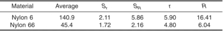
10. Precision
10.1 Precision, characterized by repeatability, Sr, r, and reproducibility, SR, R, has been determined for these materials to be:
TABLE 1 Repeatability and Reproducibility for Relative Viscosity
Material Average Sr SR r R
Nylon 6 140.9 2.11 5.86 5.90 16.41
11. Keywords
11.1 Brookfield viscosity; density of nylon polymer-formic acid solution; pipet viscosity; relative viscosity
APPENDIX (Nonmandatory Information)
X1. PROCEDURE FOR DETERMINATION OF RELATIVE VISCOSITY IN 90 % FORMIC ACID USING AN AUTOMATED TESTING DEVICE
X1.1 Scope
X1.1.1 This procedure describes the method for determin-ing the relative viscosity of a solution of nylon polymer in 90 % formic acid using an automated testing device.
X1.2 Principle
X1.2.1 The relative viscosity, RV, measured by the tech-nique described in this method is a ratio of a concentrated solution of polyamide in formic acid to the nylon solvent grade formic acid. The viscosity in centistokes (cSt) of an 8.4 % (w/w) solution of nylon in formic acid is related to the viscosity of the solvent. The viscosity of the polymer/formic acid solution is determined by measuring the time of efflux of the solution in a calibrated viscometer.
X1.3 Equipment Required
X1.3.1 Constant temperature liquid bath regulated at 25.00
6 0.1°C,
X1.3.2 ASTM Ubbelohde-calibrated viscometers,
X1.3.3 Bottles, glass or polypropylene, with screw type lids (polypropylene with or without PTFE liner) and pipets,
X1.3.4 Automated polymer viscometer system, X1.3.5 Shaker,
X1.3.6 10 mesh screen and grinder, if samples require grinding,
X1.3.7 Desiccators with Drierite desiccant, X1.3.8 Analytical balance, and
X1.3.9 Calibrated thermometer.
X1.4 Reagents
X1.4.1 90% 6 0.2 % formic acid ACS grade for testing, viscosity grade for cleaning.
X1.4.2 Acetone, reagent grade.
X1.5 Procedure
X1.5.1 Sample Preparation
NOTE X1.1—A control should be the first sample tested each day.
X1.5.1.1 Place the ground polymer in a 43-mm aluminum pan and place the pan in the vacuum oven for 20 minutes. The oven should be set at 93 64°C.
X1.5.1.2 Store the dried sample in the desiccator until ready for use.
X1.5.2 Solution Preparation
X1.5.2.1 Place a glass bottle on the analytical balance. Wait until the weight stabilizes, then carefully add the required amount of polymer to the bottle.
X1.5.2.2 Using a pipet slowly add formic acid to the polymer until the weight reaches the weight required for an 8.4 % solution. Remove the bottle from the balance and place it on a shaking device.
NOTE X1.2—Sample preparation may also be done by automated
systems.
X1.5.3 Specimen Testing
X1.5.3.1 Once the nylon has dissolved, remove the sample from the shaker.
X1.5.3.2 Make sure the liquid bath is at the proper level and at 256 0.1°C.
X1.5.3.3 Add the nylon/polymer solution to the designated viscometer.
X1.5.3.4 Initiate the test as required by the automated equipment in use.
X1.5.3.5 The automated device will draw, release and time the sample drop using photoelectric devices. Obtain two consecutive flow times for each sample within 0.2 % of the mean.
X1.5.3.6 When the test is complete the computer will use the average flow time to calculate (see 9.2.8) and display the relative viscosity value. Care should be taken to test samples promptly as experience shows that samples may degrade as much as 2 % overnight.
SUMMARY OF CHANGES
Committee D20 has identified the location of selected changes to this standard since the last issue (D 789 - 06a) that may impact the use of this standard. (September 1, 2007)
(1) Added Warning note to9.2.1.2. (2) Revised value ofhfin9.2.3.2,9.2.5,9.2.8, and 9.3.4.2. Committee D20 has identified the location of selected changes to this standard since the last issue, D 789 - 06, that may impact the use of this standard. (September 1, 2006)
(1) Changed title from Relative Viscosity to Solution Viscosi-ties.
(2) Changed relative viscosity to solution viscosities in1.1.
ASTM International takes no position respecting the validity of any patent rights asserted in connection with any item mentioned in this standard. Users of this standard are expressly advised that determination of the validity of any such patent rights, and the risk of infringement of such rights, are entirely their own responsibility.
This standard is subject to revision at any time by the responsible technical committee and must be reviewed every five years and if not revised, either reapproved or withdrawn. Your comments are invited either for revision of this standard or for additional standards and should be addressed to ASTM International Headquarters. Your comments will receive careful consideration at a meeting of the responsible technical committee, which you may attend. If you feel that your comments have not received a fair hearing you should make your views known to the ASTM Committee on Standards, at the address shown below.
This standard is copyrighted by ASTM International, 100 Barr Harbor Drive, PO Box C700, West Conshohocken, PA 19428-2959, United States. Individual reprints (single or multiple copies) of this standard may be obtained by contacting ASTM at the above address or at 610-832-9585 (phone), 610-832-9555 (fax), or [email protected] (e-mail); or through the ASTM website (www.astm.org).