HAL Id: hal-02568293
https://hal.archives-ouvertes.fr/hal-02568293
Submitted on 26 May 2020
HAL
is a multi-disciplinary open access
archive for the deposit and dissemination of
sci-entific research documents, whether they are
pub-lished or not. The documents may come from
teaching and research institutions in France or
abroad, or from public or private research centers.
L’archive ouverte pluridisciplinaire
HAL
, est
destinée au dépôt et à la diffusion de documents
scientifiques de niveau recherche, publiés ou non,
émanant des établissements d’enseignement et de
recherche français ou étrangers, des laboratoires
publics ou privés.
Joint space and workspace analysis of a 2-DOF Spherical
Parallel Mechanism
Guillaume Michel, Philippe Bordure, Ranjan Jha, Swaminath Venkateswaran,
Damien Chablat
To cite this version:
Guillaume Michel, Philippe Bordure, Ranjan Jha, Swaminath Venkateswaran, Damien Chablat. Joint
space and workspace analysis of a 2-DOF Spherical Parallel Mechanism. New Trends in Mechanism
and Machine Science, 2020, �10.1007/978-3-030-55061-5_21�. �hal-02568293�
2-DOF Spherical Parallel Mechanism
D. Chablat1, G. Michel12, P. Bordure2, R. Jha3 and S.
Venkateswaran1
1Laboratoire des Sciences du Num´erique de Nantes (LS2N), UMR CNRS 6004, Nantes, France
2CHU de Nantes, 44093 Nantes
3CSIR-Central Scientific Instruments Organisation, India
e-mail: Damien.Chablat@cnrs.fr, Guillaume.Michel@chu-nantes.fr, Philippe.Bordure@chu-nantes.fr, Swaminath.Venkateswaran@ls2n.fr, Ranjan.Jha@csio.res.in
Abstract. This paper deals with the joint space and workspace analysis of a two degree of freedom spherical parallel mechanism designed to be used to handle an endoscope. This mechanism is composed of the three legs (2USP-U) to connect the base to a moving platform. As the manipulator can get up to six solutions to the direct kinematic problem (DKP) in four aspects, non-singular assembly modes changing trajectories may exist. The aim of the paper is to check whether a regular workspace centred on home pose can be defined in such a way that no such trajectory exists in this workspace.
Key words: Spherical parallel robot, singularity, cusp point, aspect.
1 Introduction
In the context of designing a robot to assist the surgeon in otologic surgery, a spherical robot with a parallel structure associated with a double paral-lelogram was studied [1]. This robot can handle a endoscope to increase the efficiency of the surgeon with compare to classical binocular. The parallel structure should increase the rigidity compared to the existing solution [2]. Many spherical mechanisms exist in the literature and can be divided into two main families (i) those with a virtual center of rotation and (ii) those constrained by a spherical joint or a universal joint (three or two DOF) [3, 4, 5, 6, 7, 8]. To form an remote center of motion (RCM), one solution is to use to an universal joint associated with two parallelograms where the motion can be done with prismatic or revolute actuators. The advantage of prismatic actuators is that there is only one solution to the inverse geometric model or a single “working mode” [9, 10]. In order to give the surgeon more mobility, it is necessary to have the largest working space without singular-ity. By adding an offset in the classical design, we are able to increase this workspace but the properties of the robot change [11] ie the number of
2 D. Chablat and G. Michel and R. Jha and S. Venkateswaran
pects and the number of solutions to the DKP increases. In this paper we will present the robot properties for a given offset that allow non-singular assem-bly mode changing trajectories [13]. The SIROPA library written in Maple will be used to compute the singularity equations using Groebner bases, the cylindrical algebraic decompositions (CAD) as well as the trajectory plan-ning [14, 15]. The outline of this paper will be the following. We will first introduce the kinematic equations, then the singularities in the joint space and the workspace to insert a prescribed regular workspace.
2 Mechanism under study
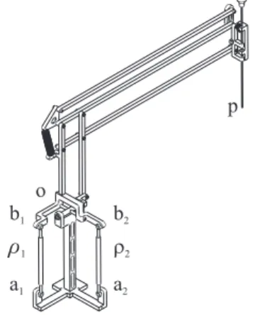
Figure 1 shows an RCM mechanism carrying an endoscope for operations in the ears made by coupling two DOF spherical mechanism with double parallelograms. This mechanism is coupled to a translation mechanism for positioning in the middle ear centre. Another mechanism allows translation of the endoscope for insertion, cleaning and ejection in case the patient wakes up, not addressed in this article. The spherical parallel mechanism is composed of three limbs and one moving platform. The two first legs, UPS, are composed of a universal joint, a prismatic joint and a spherical joint and the last one is made by a single universal joint and constrains its mobility. The two prismatic joints are actuated. The double parallelogram is attached to the two axes of this joint. Usually, the end points of the UPS legs are in the same plane as the axes of rotation of the universal joint. To increase the orientation range, an offset is added. a1 o p a2 b1 b2 r1 r2
Fig. 1 RCM Mechanism with spherical parallel mechanism in its home pose where
oandpare the centers of motions
Leta1 anda2be attached to the base, Othe center of the universal joint
and b1 and b2 be attached to the mobile platform in the moving reference
frame. The coordinates are given bya1= [1,0,−1]
T
,a2= [0,1,−1]
T , b1=
[1,0, h]T, b2 = [0,1, h]
T
. The orientation space of the moving platform is fully represented with the variables (α,β). The rotation matrixRfrom the base frame to the moving frame is expressed as follows:
R=RαRβ= cos (β) 0 sin (β) sin (α) sin (β) cos (α)−sin (α) cos (β) −cos (α) sin (β) sin (α) cos (α) cos (β)
(1)
The orientation angles are defined in such a way that α = β = 0, which represents the “home” pose as depicted in Figure 1. The coordinates of b1
andb2can be written in the base frame as
c1=Rb1 c2=Rb2 (2)
The distance constraints from the two prismatic joints are
||aici||=ρi with i = 1,2 (3)
This leads to the two constraint equations:
−2 (cos (α) +h) sin (β) + 2 (cos (α)h−1) cos (β) +h2+ 3 =ρ12 (4)
2 (cos (β)h−1) cos (α) + 2 (cos (β)h+ 1) sin (α) +h2+ 3 =ρ22 (5)
3 Singularity and workspace analysis
The singularity analysis is done by differentiating the two constraint equation with respect to time that leads the velocity model:
At+B ˙ρ= 0 (6)
whereAandB are the parallel and serial Jacobian matrices, respectively,t is the angular velocity and ˙ρ = [ ˙ρ1 ρ˙2]T joint velocities [9]. Let set h= 0,
then the singularity locus CW in the worskpace and CQ in the joint space can be written as follow:
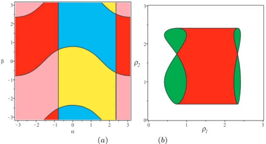
CW : (sin (α) + cos (α)) (−cos (α) cos (β) + sin (β)) = 0 (7) CQ : ρ42−6ρ 2 2+ 1 (8) 4ρ81+ρ82−48ρ61−12ρ62+ 168ρ41+ 46ρ42−144ρ21−60ρ22+ 45 = 0 Upon factorization of both the equations, there exists four solutions to the DKP out of which only four aspects, ie the maximum singularity free regions, can be found which are represented in Figure 2(a) [9]. In the joint space,
4 D. Chablat and G. Michel and R. Jha and S. Venkateswaran
Figure 2(b), there are regions depicted in green where the DKP admits two real solutions and in red where there are four real solutions.
(a) (b)
Fig. 2 Singularity locus in the workspace (a) and the joint space (b) withh= 0
The objective of our study is to use the robot for the largest possible range of motion, depending on the size of the ear and the placement of the patient in relation to the robot. The expressed need is a workspace close to ±60 degrees which we will keep as ±1 radians. Several design parameters can be varied to increase the workspace without singularity. We have chosen to study variations inhto keep the mechanism as compact as possible. Unfortunately, the properties of the robot are not stable when h is different from 0 and the locus of the singularities changes and the equations cannot be factorized. The singularity as a function of parameterhcan be depicted in Figure 3. A regular range of [−1 1] can be observed forα andβ. Several values can be considered forhbut this optimization could not be done in this article due to lack of space. Thus, a value ofh= 1 will be considered. This value allows to have well separated curves in the joint space and workspace as shown in Figure 4 and also include the regular workspaceα=β= [−1 1].
Forh= 1, the singularity locus in the workspace is defined as
2(Cβ+Sβ+ 1)Cα2+ (2Cβ2+ (−2Sβ+ 2Sα+ 2)Cβ+ (−2Sα+ 2)Cβ2 + (2Sβ−2)Sα−2Sβ)Cα+ ((2Sβ+ 2)Sα+ 2Sβ)Cβ−2SαSβ= 2 (9)
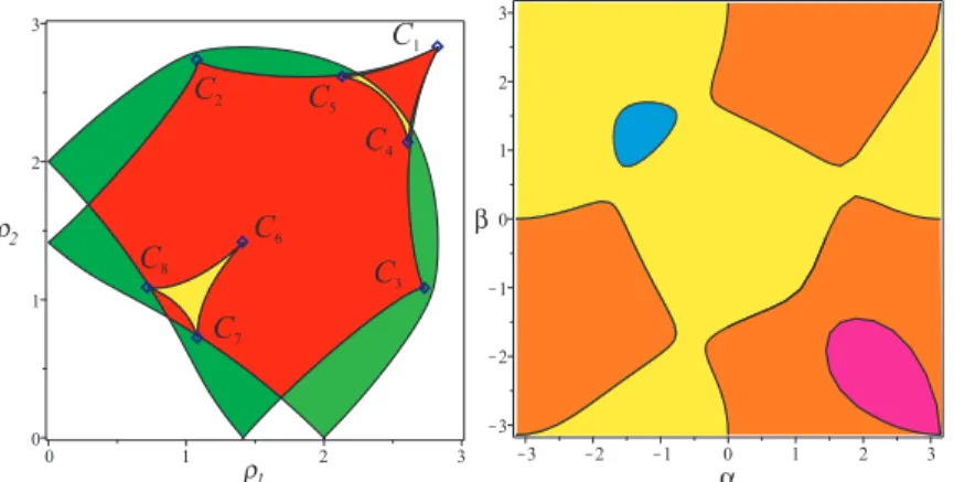
The first analysis that can be done in the joint space will be to evaluate the number of real solutions to the DKP. In Figure 4 in the joint space, the green regions admit two real solutions to the DKP, the red regions admit four solutions and the yellow regions admit six solutions. Eight cusps exist, (i)C1is on the border of the joint space, (ii)C2andC3are between the
Fig. 3 Singularity locus in the workspace of the spherical joint forh∈[0..1.5]
C8are between the four- and six-solution regions. The workspace consists of
four colour aspects in orange, pink, blue and yellow.
C2 C 5 C4 C1 C3 C7 C6 C8
Fig. 4 Joint space with height cusps points,Ci and workspace with four aspects
withh= 1
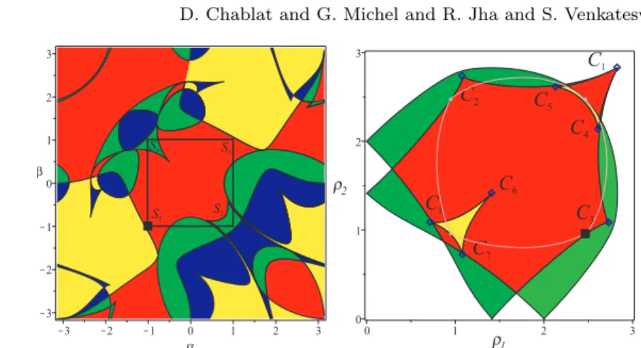
To know if the mechanism changes assembly mode in the workspace defined byα=β ∈[−1 1], a trajectory is defined along this boundary, through the S1,S2,S3,S4points, as well as its image in the joint space (Figure 5). We can
notice that the trajectory surrounds 3 cusp points C4, C5 and C6. Indeed,
knowing that the trajectory is inscribed in an aspect, it does not allow to know if it is in the same uniqueness domain i.e. there is no change in the assembly mode.
To investigate the properties of the workspace, the characteristic surface must be studied. This notion was introduced in [16] to define the uniqueness domains for serial robots and was extended to parallel robots with one inverse
6 D. Chablat and G. Michel and R. Jha and S. Venkateswaran S1 S2 S4 S3 C2 C 5 C4 C1 C3 C7 C6 C8
Fig. 5 Regular trajectory in the workspace and its image in the joint space
kinematic solution in [13], several inverse kinematic solutions in [12] and several operation modes [17]. These characteristic surfaces (or curve in 2D) are the images in the workspace of the singularity surfaces. By using the singularity and characteristic surfaces, we can compute the basic regions as defined in [13]. The joint space is divided by the singularity surfaces in regions where the number of solutions for the DKP is a constant. These regions can also be named as thebasic componentsas in [13]. The existence of cusp points could be noticed in Figure 5. Thus, it is very easy to recognize images of cusp points in the workspace, either it is a point on a tangent between a singularity curve and characteristic curve or it is a cusp point and it has no influence on the trajectories [18]. In the joint space, this trajectory encircles three cusp points. A similar behaviour as described in [19] can be obtained. The image in the workspace of a loop in the joint space can be (i) the loop in the same aspect with the same starting and target point, (ii) a trajectory where the starting point and target point are in two aspects (a singular trajectory), or (iii) a trajectory where the starting point and target point are in the same aspect (a non-singular mode assembly trajectory).
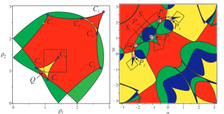
In Figure 6, a joint trajectory is defined to encircle a cusp point. The starting point, Q, is located in the yellow region where the DKP admits six real solutions Pi, depicted in the workspace. The images of this trajectory in the workspace are located in basic regions depicted in yellow and blue regions where det(A) > 0 and in basic region depicted in red and green where where det(A)<0. In Figure 7, we can observe from any stating point Pi (i) two singular trajectories between two aspects (P4−P6 and P5−P6)
and meet singular positions in S1 andS2, respectively, (ii) one non-singular
changing trajectory in the same aspect (P4−P5), and (iii) three loops in the
workspace located in the same aspect (P1−P1,P2−P2,P3−P3). Only the
trajectory (P1−P1) is located in the regular workspace. So we can conclude
that even if this trajectory surrounds a cup point in the joint space, it is not a non-singular changing assembly mode trajectory.
C2 C5 C4 C1 C3 C7 C6 C8 Q P1 P6 P4 P2 P5 P3 S1 S2
Fig. 6 Trajectory that encircles a cusp point in the joint space and its image in the workspace
P
1P
6P
4P
2P
5P
3S
1S
2Fig. 7 Zoom on the trajectories in the workspace
4 Conclusions
The properties of a 2-DOF spherical parallel mechanism were studied in this article. The increasing size of the workspace yields to several changes as the increasing number of solutions to the direct kinematics problem. Four as-pects were described by using cylindrical algebraic decomposition. A regular workspace is inscribed around the home pose. Joint limits on the passive joint αandβ guarantees that non-singular assembly mode trajectory may appear. Additional research shall be conducted to verify the collision between the legs and the limits of the passive joints and to investigate variations in other design parameters.
8 D. Chablat and G. Michel and R. Jha and S. Venkateswaran
References
1. Schena, B., Robotic manipulator with remote center of motion and compact drive, Patent WO 2008/157225 (2007).
2. Rosen, J., Brown J.D., Chang, L., Barreca, M., Sinanan, M., Hannaford, B., The Blue-DRAGON - a system for measuring the kinematics and dynamics of min-imally invasive surgical tools in-vivo, In: Proc. IEEE International Conference on Robotics and Automation (2002).
3. Gosselin, C., Hamel, J.-F., The agile eye: a high-performance three-degree-of-freedom camera-orienting device. In: Proc. IEEE international conference on robotics and automation, pp. 781–786 (1994).
4. Cheng H.H., Real-time manipulation of a hybrid serial-and-parallel driven re-dundant industrial manipulator. ASME J. of Dynamic Systems, Measurement and Control, 116(4), pp. 687–701 (1994).
5. Agrawal S.K., Desmier G., Li S., Fabrication and analysis of a novel 3 dof parallel wrist mechanism, ASME J. of Mechanical Design, 117(2), pp. 343–345 (1995). 6. Caron, F., Analyse et d´eveloppement d’un manipulateur parall`ele sph´erique `a
deux degr´es de libert´e pour l’orientation d’une cam´era, M.Sc., Universit´e Laval, Qu´ebec, August (1997).
7. Karouia M. and Herv`e J.M. A three-dof tripod for generating spherical motion, In ARK, pp.395–402, Piran, 25-29 June (2000).
8. Li, J., Zhang, G., M¨uller, A., Wang, S., A family of remote center of motion mechanisms based on intersecting motion planes. Journal of Mechanical Design, 135(9) (2013).
9. Chablat, D., and Wenger P., Working modes and aspects in fully parallel ma-nipulators; Proceedings, 1998 IEEE International Conference on Robotics and Automation, Vol. 3 (1998).
10. Bonev, I. A., Chablat D., and Wenger P., Working and assembly modes of the Agile Eye, Proceedings 2006 IEEE International Conference on Robotics and Automation (2006).
11. Kumar, S., Nayak, A., Peters, H., Schulz, C., M¨uller, A., Kinematic analysis of a novel parallel 2SPRR+ 1U ankle mechanism in humanoid robot, International Symposium on Advances in Robot Kinematics. Springer, Cham (2018). 12. Chablat D., Wenger P., S´eparation des solutions aux mod`eles g´eom´etriques direct
et inverse pour les manipulateurs pleinement parall`eles, Mechanism and Machine Theory, Vol 36/6, pp. 763–783, (2001).
13. Wenger Ph., Chablat D., Definition Sets for the Direct Kinematics of Parallel Manipulators, 8th International Conference in Advanced Robotics, pp. 859–864 (1997).
14. Jha, R., Chablat, D., Baron, L., Rouillier, F., Moroz, G., Workspace, joint space and singularities of a family of delta-like robot, Mechanism and Machine Theory, 127, pp. 73–95, (2018).
15. Chablat, D., Moroz, G., Rouillier, F., Wenger, P., Using Maple to analyse parallel robots. In Maple Conference 2019, October, (2019).
16. Wenger P., A new general formalism for the kinematic analysis of all nonredun-dant manipulators, IEEE Robotics and Automation, pp. 442–447 (1992). 17. Chablat, D., Jha, R., Rouillier, F., Moroz, G, Non-singular assembly mode
chang-ing trajectories in the workspace for the 3-RPS parallel robot. In Advances in Robot Kinematics (pp. 149–159). Springer, Cham (2014).
18. Chablat, D., Moroz G., Wenger P., Uniqueness domains and non singular assem-bly mode changing trajectories, 2011 IEEE International Conference on Robotics and Automation (2011).
19. Mazen Z., Wenger P., Chablat D., Non-singular assembly-mode changing mo-tions for 3-RPR parallel manipulators, Mechanism and Machine Theory 43.4, pp. 480–490, (2008).