Concurrent Engineering Workflow
CONFLOW - a project funded by the Commission of the European Communities under the INCO-Copernicus programme (project no. 960243)
Partners:
• Technische Universität Clausthal, Germany
• University of Wales Cardiff, United Kingdom
• Mummert + Partner Unternehmensberatung AG, Hamburg, Germany
• University of Rousse, Bulgaria
• Technical University of Budapest, Hungary
• ZITA Ltd, Rousse, Bulgaria
• SAGE Ltd, Budapest, Hungary
Product Characteristics Determining
Engineering Processes
Authors:
Dr. Krastimir Popov, Katalina Grigorova, Daniela Tsaneva, University of Rousse
Deliverable No.: 3.1
Document No.: CONFLOW.97.12
Contents
SUMMARY...3
1. Introduction...4
2. Product Characteristics Analysis ...5
2.1 Incorporating the Quality into the Design...5
2.2 Customer/Market Requirements Specification...5
2.3 Determining Product Characteristics...7
2.4 Examples of Product Characteristics Determining...10
3. Product Characteristics Representation...14
3.1 Product Structure ...14
3.1.1 Bill of Materials ... 14
3.1.2 Feature-based Models ... 17
3.1.3 Integration of Bill of Materials and Feature-based Models ... 18
3.2 Interdependencies between Product Characteristics...19
3.3 Interdependencies between Features ...19
4. Conclusions ...20
SUMMARY
The purpose of this task is to analyze the product characteristics determining engineering process whose changes result in product design. Apparently all product attributes have an influence on the engineering process and have to be examined.
The deliverable contains product characteristics analysis and product characteristics representation. Product characteristics analysis includes the following steps: defining the quality required for the design of a certain product, preparing a customer requirements specification and determining product characteristics.
Product characteristics representation begins with determining product structure as bill of materials and feature-based models. Then an approach for integration of bill of materials and feature-based models is presented to obtain the ConFlow aims. This approach consists of extending feature descriptions generated by CAD system with additional non-shape properties, generating BOM for the same product from the PDM system, connecting both product structure representations by the ISO code of material and the topological parameter parent. Connections between features determine other affected features that have to be changed as a result of any feature change. These modifications reflect on the processes related to the influenced features. In the next sections the interdependencies between product characteristics and interdependencies between features are mentioned.
The suggested approach will be developed during the next tasks of the project. Representations of the case studies presented in the WP1 will be prepared as examples.
1. Introduction
Constantly changing market conditions tend to reducing product cost and time to market and the tendency to manufacture products with satisfactory quality for different customers, demand development of new products, as well as recreation of existing products by modifying them or generation their variants. The first step of this process is investigation of market conditions and product requirements specification. It is necessary to define the exact requirements specifying product of the proper quality for the certain customers with the right performance (it is not always needed to manufacture high quality products with high performance).
The first stage of product development is customer/market requirements specification defining the product of stated quality. On the design stage these requirements are transformed into product characteristics. This process is followed by smoothing the contradictions between different requirements and determining the relative importance of each characteristic. During the embodiment design product characteristics are converted into product parts characteristics. These, on their side, define the engineering processes performed during the product manufacturing, product costs and time to market calculations.
Products and parts characteristics can be classified according to distinct criteria. Normally, part characteristics are separated aiming to present different aspects of product performance and manufacturing: geometric characteristics, topological characteristics, technological characteristics, functional characteristics, etc. Each of these characteristics on its own way affect on the product design, process planning and product manufacturing or each engineering process is a result of the given product characteristics influence. After finishing the product development all the production documentation is prepared.
Product development team activities are assisted by software systems dealing with different aspects of product design and product manufacturing. Product characteristics are elements of product structure which is presented in each of these systems. Generally, two ways of product structure representation exist: Bill of Materials and Feature-based Models. These two ways are connected with two separated directions of product development: product design, which is the main activity of CAD systems and production preparation which is the main activity of PDM systems. Integration of these two representations can be used to realize product characteristics influences onto the overall product development. Each characteristic can be transformed into element of bill of materials and feature-based model. The product characteristics changes would reflect on both representations. Changes processing is partly solved by using variant bill of materials and variant features.
Each of the above mentioned representation methods allow to describe some interdependencies between their elements. The link between these representations leads to extension the possibilities of interdependencies description.
2. Product Characteristics Analysis
2.1 Incorporating the Quality into the Design
Product design is the first step in the manufacturing process. All of the opportunities for, and limitations on efficiency in manufacturing, are established at the product design level.
Ideas that lead to the development of new product may come from several sources. Usually ideas come from company executives, company sales force, customer suggestions, governments agencies, and research laboratories. It should be apparent that not every idea necessarily leads to a new product that is placed on the market. However, every new product represents the crystallization of someone’s idea. Selecting the right product is performed considering the most important factors influencing on it. Some of these are:
• the need for the product
• the product’s sales appeal
• the advantages and improvements over similar products on the market
• the size of the potential market
• the patentability of the product
• the expected life of the product
• the compatibility of the product with other company products
• research and development costs
• suitability of engineering and facilities
• suitability of sales and distribution
All these requirements in fact determine the quality of the new product. Quality cannot be inspected into a product but must be designed and built into it. Tolerances, machine finish, material specifications, and performance requirements must be specified so as to assure a product that is of sufficient quality.
2.2 Customer/Market Requirements Specification
Determining customer requirements is very important to make an accurate specification of the product performance. The performance specification method is intended to help in defining the design problem, leaving the appropriate amount of freedom to the designer. A specification defines the required performance, and not the required product. The method therefore emphasizes the performance that a design solution has to achieve and not any particular physical components.
Requirements specification is a result of the following procedure:
• Consider the different levels of generality of solution which might be applicable
It is important that a specification is addressed to an appropriate level of generality for the solution type that is to be considered. A specification at too high a level of generality may allow inappropriate solutions to be suggested, whereas too low a level (a specification which is too specific) can remove almost all of the designer’s freedom to generate a range of acceptable solutions.
So the first step is to consider the different levels of generality. A simple classification of types of level, from the most general down to the least, for a product might be:
- product types
- product characteristics
At the highest level of generality the designer would be free to propose alternative ways of designing. At the intermediate level, the designer would have a much more limited freedom, and might only be concerned with different types of appliances. At the lowest level, the designer would be constraint to considering different features within a particular type of appliance.
• Determine the level of generality at which to operate
Considering the different levels of generality might lead to either a broadening or a narrowing of initial product concepts or of the design brief. The second step of the method is therefore to make a decision on the appropriate level.
Normally, the client, company management or customer decides the level at which the designer will operate. The highest level of generality (‘alternatives’) would only be considered if an appliance manufacturer was proposing to diversify or broaden its activities into other aspects. The intermediate level (‘types’) would normally be considered when a new product was to be designed, to add to the existing range of appliances or to replace obsolete ones. The lowest level (‘characteristics’) would be considered when making modifications to existing products.
The higher the level of generality that may be considered, the more freedom the designer has in terms of the range of acceptable solutions. Of course, the higher level also subsumes the lower levels of specification - that is, the specification of characteristics is part of the specification of types which is part of the specification of alternatives.
• Identify the required performance analysis
Once the level at which designing is to proceed has been decided, work can begin on the performance specification proper. Any product or machine will have a set of attributes, and it is these which are specified in the performance specification. Attributes include such things as comfort, portability and durability and key features such as speed, cost and safety.
Performance attributes are usually similar to, or derived from, the design objectives and functions. So if you have already prepared an objectives tree or a function analysis, these are likely to be the source of your initial list of performance attributes.
A most important aspect to bear in mind when listing performance attributes is that they should be stated in a way which is independent of any particular solution. Statements of attributes made by clients or customers are often couched in terms of solutions, because they value some performance aspect which is embodied in the solution but they have not separated the attribute from a particular embodiment. Such solution-based, rather than performance-based, statements are usually unnecessarily restrictive of solution concepts.
There may be a whole complex of reasons underlying a client or customer specification of a particular solution feature. A comprehensive and reliable list of performance attributes can therefore take some considerable effort to compile and may well require careful research into client, customer, and perhaps manufacturer requirements.
The final list of performance attributes contains all the conditions that a design proposal should satisfy. However, it may become necessary to distinguish within this list between those attributes or requirements that are ‘demands’ and those that are ‘wishes’. ‘Demands’ are requirements that must be met, whereas ‘wishes’ are those that the client, customer or designer would like to meet if possible.
• State precise performance requirements for each attribute
Once a reliable list of attributes has been compiled, a performance specification is written for each one. A specification says what a product must do, not what it must be. Again, this may well require some careful research - it is not adequate simply to guess at performance requirements, nor just to take them from an existing solution type.
Wherever possible, a performance specification should be expressed in quantified terms. Also wherever possible and appropriate, a specification should set a range of limits within which acceptable performance lies.
2.3 Determining Product Characteristics
In determination a product specification, conflict and misunderstanding can sometimes arise between the marketing and the engineering members of the design team. This is usually because they focus on different interpretations of what should be specified. Managers and market researchers tend to concentrate more on specifying the desirable attributes of a new product (usually from the viewpoint of customer or client requirements), whereas designers and engineers concentrate more on a product's engineering characteristics (usually in terms of its physical properties).
The relationship between characteristics and attributes is in fact a very close one, and confusion can be avoided if this relationship is clearly understood. Designers make decisions about the product's physical properties, and thus determine its engineering characteristics; but those characteristics then determine the product's attributes, which in turn satisfy the customer's needs and requirements. Thus, for example, the engineering designer may choose a particular metal casing for a product, of a certain gauge and surface finish, thus determining characteristics such as weight, rigidity and texture; these characteristics determine product attributes such as portability, durability and appearance.
With increased competition in all product markets, it has become necessary to ensure that this relationship between engineering characteristics and product attributes is properly understood. In particular, it is necessary to understand just what customers want in terms of product attributes and to ensure that these are carefully translated into specifications of the appropriate engineering characteristics. This attitude towards product design is based on the philosophy of 'listening to the voice of customer', and is reflected in an increased concentration on product quality. Design for quality is recognized as a major factor in determining the commercial success of a product.
A comprehensive method for matching customer requirements to engineering characteristics is the quality function deployment method (QFD). The QFD method recognizes that the person who buys (or who most influences the buying decision for) a product is the most important person in determining the commercial success of a product. If customers do not buy it, then the product - however 'well-designed' it may be - will be a commercial failure. Therefore 'the voice of the customer' has priority in determining the product's attributes. This means taking care to identify who the customers are, to listen carefully to what they say, and to determine the product's engineering characteristics in the light of this.
QFD is essentially concerned with the translation of customer requirements into engineering characteristics, and it is presented here at the core of the design process. However, because it is a comprehensive method, aspects of QFD can be used at various stages of the design process, and it also draws upon features from several other design methods. The following procedure presents the steps of QFD method:
• Identify customer requirements in terms of product attributes
The method starts with the identification of customers and of their own views of their requirements and desired product attributes. There are various market research techniques that can be used to assist the gathering of information about customer requirements and preferences. These methods include product 'clinics' where customers are quizzed in depth about what they like and dislike about particular products, and 'hall tests' where various competing products are arranged on display in a room or hall and customers are asked to inspect the products and give their thoughts and reactions.
Usually, of course, customers will talk about products in terms of both general attributes and specific characteristics - observations ranging from 'It's easy to use' to 'I don't like the color'. As in the performance specification method, it may be necessary to interpret the more general statements into more precise statements of requirements. It is important to try to identify and to preserve the customers' wishes and preferences, rather than to reinterpret their observations into the designer's perceptions of what the customers 'really mean'. For this reason, words and phrases actually used by customers are often retained in statements of product attributes, even though they may seem to be vague and imprecise.
• Determine the relative importance of the attributes
Of course, not all the identified product attributes will be equally important to customers. For example, 'easy to use' may be regarded as much more important than 'easy to maintain'. Also, some requirements (as noted in the performance specification method) may be 'demands' or absolute requirements (e.g. 'safe to use') rather than relative preferences.
The design team will want to know which attributes of their product design are ones that most heavily affect customers' perceptions of their product, and so it is necessary to establish the relative importance of those attributes to the customers themselves. Again market research methods can help to establish these relative preferences, and provide confirmation of whether what customers say they want is actually reflected in what they buy.
Some relatively simple techniques can also be used in order to access the relative importance of the identified attributes. For example, customers can be asked to rank-order their statements of requirements, or to allocate 'points' (preferably from a fixed maximum points allowance) to the various attributes.
The outcome of this step in the procedure is the allocation of relative 'weights' to the set of customer-specified product attributes. Normally, a percentage value is set for each attribute, i.e. the weights for the complete set of attributes add up to a total of 100.
• Evaluate the attributes of competing products
Customers often make judgments about product attributes in terms of comparisons with other products. This use of comparisons is perfectly understandable, having in mind that customers are not usually experts and can only guess at what is possible in product design through observation of what some products actually achieve. Market research information is also often collected by methods of comparison between products.
In a competitive market, therefore, the design team has to try to ensure that its product will satisfy customer requirements better than the competitor products. The performance of the competition is therefore analyzed, particularly with regard to those product attributes that are weighted high in relative importance. Some of these performance measures will be objective and quantitative, whilst some will be subjective comparisons as made by customers. However, even when objective measures can be made, these should be checked against the customers' perceptions, which may not correspond with the objective measures.
In designing the new product, there may not be many competitor products, but that would be unusual; most product designs have to compete against existing products already on the market. In those cases where a design team is redesigning or improving and existing product, this step in the procedure not only highlights where improvements to the design team's product may be necessary, but also where this current product already has advantages over the competition, which should be maintained. The performance scores for the team's own current product and for the competition should be listed against the set of product attributes.
• Draw a matrix of product attributes against engineering characteristics
As suggested above, customers are not experts and therefore cannot usually specify their requirements in terms of the product's engineering characteristics that influence those requirements. It is therefore necessary for the design team to identify those engineering characteristics of their product that satisfy or influence in any way the customer requirements. The engineering characteristics must be real, measurable characteristics over which the engineering designer has some control. It is understandable for customers to be rather vague about their requirements, or to express them in subjective terms, but the engineering designer can only work with the quantitative parameters of identifiable engineering characteristics. It is through the adjustment of the parameters of those characteristics that the designer influences the performance and/or customer's perception of the product. Therefore it is often necessary to put considerable effort into identifying the relevant engineering characteristics and ensuring that each of these can be expressed in measurable units.
Of course, not all engineering characteristics affect all product attributes, and drawing up a matrix will enable the team to identify which characteristics do affect which attributes. It is usual to list the attributes, together with their relative weights, vertically, down the left edge of the matrix, and the characteristics horizontally, along the top edge. The attributes thus form the rows of the matrix, and the characteristics form the columns. Each cell of the matrix represents a potential interaction or relationship between an engineering characteristic and customer requirements.
Down the right edge of the matrix can be listed the results of the evaluation of competing products, showing the scores achieved against the product attributes for the competing products and the design team's own current product. Along the bottom edge of the matrix is the usual place for recording the units of measurement of the engineering characteristics. If a product already exists and is being redesigned then the product's own values for these characteristics can also be inserted here, together with values achieved by competitor products.
• Identify the relationships between engineering characteristics and product attributes
By checking through the cells of the matrix it is possible to identify where any engineering characteristic influences any product attribute. These relationships between characteristics and attributes will not all be of equal value. That is to say, some characteristics will have a strong influence on some attributes, whilst other characteristics might only have a weak influence. The design team therefore works methodically through the matrix, and records in the matrix cells wherever a relationship occurs, and the strength of that relationship. Sometimes numbers are used to represent the strength of the relationship (e.g. 6 for a strong relationship, 3 for a medium-strength, 1 for a weak relationship), or symbols can be used. When numbers are used, it is possible to enter a second value in each cell, which is the relative weight of the attribute multiplied by the strength of the relationship. The larger scores amongst these values enable the design team easily to identify where the adjustment of engineering characteristics will have a large influence on customers' overall perception of the product. However, unless
accurate measures of the strength of the relationships can be established, it must be remembered that there is a spurious accuracy implied by the numbers.
• Identify any relevant interactions between engineering characteristics
It is often the case that engineering characteristics interact with each other, particularly in terms of their influence on customers' perceptions of the product. These interactions can be either negative or positive.
A simple way of checking these interactions is to add another section to the interaction matrix. This new section is usually added on top of the existing matrix, and because it provides a triangular-shaped 'roof' to the matrix the resulting diagram is often referred to as the 'house of quality'.
Working through the 'roof' matrix enables a systematic check to be made of the interactions between the engineering characteristics, and whether these interactions are negative or positive. However, many assumptions may have to be made about the final design when completing the 'roof' matrix, and it should be remembered that changes in the design concept may result in changes in these interactions.
• Set target figures to be achieved for the engineering characteristics
In following this method so far, the design team will already have gained substantial insight into their product design, including customer perceptions of their product and of competing products, and how the engineering characteristics of the product relate to customer requirements. In this step of the procedure, the team determines the targets that can be set for the measurable parameters of the engineering characteristics in order to satisfy customer requirements or to improve the product over its competitors.
Of course, in a competitive situation it is important to know what the competitors achieve on the characteristics of their product, so detailed investigation of competitor products may be necessary. The design team can then set targets for themselves which would be better than the competition. Sometimes it may be necessary to conduct trials with customers in order to determine what would be acceptable target figure to set. This is similar to determining values in a performance specification.
2.4 Examples of Product Characteristics Determining
Example 1: Using the possible links in a CAD system for connecting the different parts of the Manometric Thermoregulator
This example illustrates how a CAD system can connect (or include) different elements used in the designing process to satisfy designer‘s requirements for a simple product. It is a design for a new product type -- Manometric Thermoregulator.
Figure shows different type of links used for this design problem. The design team works separately on designing the different parts, and then organized this information into product structure scheme. Here many objects created by different Application programs (CAD system, Spreadsheet Systems –Excel, DBMS—Access, URL‘s etc).
Since there were no comparable products already on the market, the team could not evaluate the attributes of competing products. These alternatives are given here as different drawing parts placed in the branches of the structural scheme. Making changes in every different object final design of the assembly object is then established, related to the desired product attributes.
First Object VDU Object ID 3423
Example 2: Adjusting screw for Manometric Thermoregulator
This example shows a relatively simple product. On the other hand it illustrates how much considerable efforts in designing are necessary to satisfy customer requirements even for simple products.
It is a design for a new product type -- an Adjusting screw for Manometric Thermoregulator. Normally such Thermoregulator have no Adjusting screw, but for circumstances in which the user wish to regulate the Hollow membrane position, a detachable Adjusting screw was thought to be a potentially desirable product.
Figure shows the interaction matrix prepared for this design problem. The design team interviewed users and asked them what features they would like to see incorporated in a detachable Adjusting screw, and then organized this information (retaining 'the voice of the customer' as far as possible) into product attributes. Additional requirements from the sponsor of the project were also added, such as cost, time and manufacturing requirements. These are all listed, in groups, down the left edge of the matrix.
Some of the requirements were 'musts', i.e. they had to be satisfied absolutely, whereas others could be weighted relative to each other. These relative weights are listed alongside the requirements, and the absolute requirements are marked with an asterisk.
Since there were no comparable products already on the market, the team could not evaluate the attributes of competing products. However, they decided to make comparisons with two other possible means of regulating. The evaluations of these alternatives are given down the right edge of the matrix. Engineering characteristics for a Adjusting screw design were then established, related to the desired product attributes. For example, the 'easy to attach' attribute could be measured.
3. Product Characteristics Representation
3.1 Product Structure
The product structure provides a hierarchical classification of the items which form a product. With the product structure, the understanding of the components which compose a product as well as their attributes, can be represented. This representation is used to produce the production product structure of the process which contains several manufacturing levels of material, component parts and subassemblies. In determining material requirements, the following two cases must be considered:
• a given component can exist in its own right as a uniquely identified physical entity (for example, raw material, component part, subassembly),
• a compound can exist physically as an already assembled object of another inventory
item (that is, it has lost its identity).
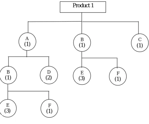
It is necessary to identify all the basic items in developing the material requirements planing system. This is done by using the bill of materials which reflects the product structure levels by listing components of each assembly and subassembly. A typical structure of a product is shown in Figure 3.1. To define a product structure it is necessary that :
• each component, part, subassembly, assembly and end item must have a unique part
number.
• the structural bill of materials must be up-to-date and accurate. 3.1.1 Bill of Materials
Manufacturing Requirements Planning (MRP) systems typically rely on a Bill of Materials (BOM) and the product structure for their information. In theory, the BOM can and should be produced automatically by the CAD system but in practice there is usually human intervention or even re-entry. The main reasons are:
• the difficulty of tracking changes to the BOM (product structure) and effectivity dates and transferring this data back to the design system. Many changes, such as different suppliers for fasteners, do not affect the design form, fit and function and are therefore only made and stored in the manufacturing systems.
• the need in manufacturing to view the product structure differently. It is often necessary to batch similar components from different products together for mass production or efficient purchasing.
PDM technology enables changes to be tracked and implemented through the design and engineering change process and then passed over to the MRP system when approved. Therefore PDM systems use BOM to represent configuration management of the product. A Bill of Materials is a product data structure which captures the end-products, its assemblies, their quantities and relationships. The structure of a part’s list determines the accessibility of the part’s information by various departments in a company. It also helps to determine the level of burden put on the computational device in searching for product information. In many companies the BOM is structured for the convenience of individual departments. This, however, engenders problems in other departments.
In Figure 3.1 a product named product 1 is shown graphically with the summarized products structure and the number of all items that are needed to make the parent products are enclosed
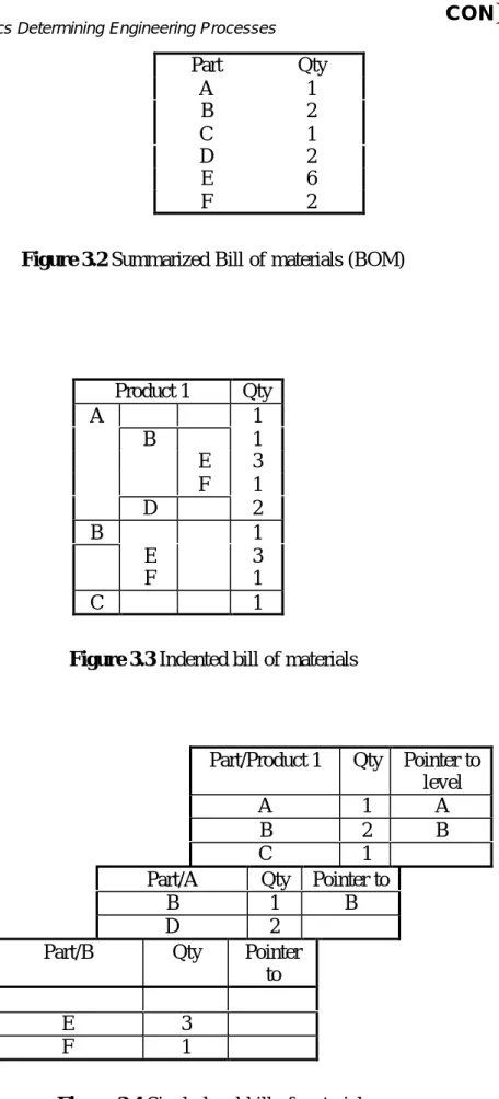
in brackets. Figure 3.2 contains a bill of materials for product 1 in which the total usage of each item is collected into a single list for the product. This kind of list is convenient for the master production schedule but results in the duplication assemblies. This implies that each product bill that uses assembly must be changed whenever there is a change in assembly. Furthermore, since lead times of intermediate assemblies cannot be determined, parts are ordered too early the first time they are encountered in the product structure.
Figure 3.1 Product structure for product 1
Other arrangements used in arranging the bill of materials is by indenting the product data as shown in Figure 3.3. One disadvantage of this method is that all components of an assembly are repeated each time the assembly is used, resulting in massive duplication of data.
One solution to the duplication problem is by holding each assembly only once in ‘single-level’ bill of materials as shown in Figure 3.4. In this approach it identifies only the components used by one level and a required subassembly. This means that engineering changes can be made in only one place.
None of the file structures described above actually show when an item is used on all the assemblies and products. Some systems maintain a separate file just for this, thereby causing maintenance problems. When bills of materials are included in the product definition database in such a way that assembly data is included only once, then maintenance such as deletions, additions and changes to the structure are simplified. In this structure retrieval can be in any desired format described above including: summarized, included, single-level and where-used. Product 1 A (1) (1)B (1)C B (1) D (2) E (3) F (1) E (3) F (1)
Part Qty A 1 B 2 C 1 D 2 E 6 F 2
Figure 3.2 Summarized Bill of materials (BOM)
Product 1 Qty A 1 B 1 E 3 F 1 D 2 B 1 E 3 F 1 C 1
Figure 3.3 Indented bill of materials
Level 1 Part/Product 1 Qty Pointer to
level
A 1 A
B 2 B
C 1
Level 2 Part/A Qty Pointer to
B 1 B
D 2
Level 3 Part/B Qty Pointer
to
E 3
F 1
Figure 3.4 Single-level bill of materials
There are usually two kinds of bills of materials needed for a product: engineering and manufacturing BOM. The engineering bill of materials usually lists items according to their
relationships with parent product. But this may not be sufficient to show that manufacturing constraints or tolerances may force the arrangement on the product structure to be different in order to assure manufacturability. Thus, engineering and manufacturing will usually have different valid views for the same product.
The table below shows the typical information which can be found in a bill of materials:
Type of material used Tools and dies used
Part name Part identification number
Parent product Quantity needed
Classification number Type of standard part
Measuring units used Process plan number
Part source Part weight
Version number Validity status
Production status Value of part
Drawing number Drawing format
Part description file
3.1.2 Feature-based Models
The objective of a product model is to generate e scheme necessary for the development, manufacture and use of a product, whereby a product may be a complete assembly, a subassembly or a part. Many of CAD systems present product structure by feature-based models.
Features are shape elements of product components with some engineering meaning attached to them. Product model is generated as a combination of features. These are manipulated using operations as insert, delete, update and product model is modified in this way. This definition of features as shape elements (form features) is sufficient for geometric modeling of the product. The feature is defined to carry the information of the elements related to its nominal geometry: thus, form features are the major concern in this description for the purpose of manufacturing planning. Form features are important for a variety of reasons:
• they contain geometric elements (vertices, edges, and faces) and these elements may be
used as the input to mathematical definitions used for matching extracted features against ones in the database;
• they provide the ‘actual structure of configuration’ of features, and can become the basis for establishing features for other purposes;
• they can be interpreted by reasoning about the current output from a CAD database;
• they can have an application-independent classification at the highest level.
On the other hand, features can be stated as data sets related to the different aspects of product model elements. These aspects can be represented by features properties. By giving certain properties, features are described as belonging to various application domains. The following types of features are distinguished:
• design features - describe the essence of features by implying function in the form of
feature geometry. It captures both geometrical and functional implications of a feature and is a set of surfaces together with specifications of the bounding relationships between them and which imply an engineering function (or stereotypical entity) on an object and
which may be formed on the faces, edges, or corners of an object. This means that all the surfaces of an object are feature surfaces.
• manufacturing features - they are of great importance for selecting appropriate machines, tools, fixtures and material processing methods. They can be of potential use in specific design processing as design for assembly and design for manufacturing, as well as for manufacturability evaluation.
• material features - they present some aspects of material machining, tools selection,
material treatment, material composition and condition.
Each product includes a set of features. Features are designed to present any product characteristics. Also features are used to present some functions. Features are application specific and they support multiple views, e.g. design, process planning and assembly. Although in most cases features are designed to depict product and its parts characteristics, some features are used for other purposes:
• performance related purposes, corresponding to the product performance characteristics
• process related purposes, corresponding to manufacturing process requirements
• ergonomic related purposes, corresponding to the ergonomic requirements. 3.1.3 Integration of Bill of Materials and Feature-based Models
In nowadays CAD systems feature-based models are used to describe the product structure, as well as some directions of design, process planning and manufacturing, whilst in PDM systems the product structure is presented by bill of materials (BOM). These representations are sufficient for achieving the objectives and goals of such types of systems. The software developers work on extending their systems functionalities so that they become closer and closer. Feature-based models are used not only in CAD systems but also in CAPP, CIM, CAM and PDM systems. Form features applied in CAD systems contain some information that can be useful for the purposes of other systems but it is not sufficient. This requests the development of different kind of features containing information that is more appropriate for using in CAPP, CIM, CAM and PDM systems. Usually, such information is presented in BOMs. Therefore, combining of these two representation methods could extent the functionality of a specific system.
A similar approach can be applied for obtaining the ConFlow project aims:
• extending feature descriptions generated by CAD system (e.g. Pro/ENGINEER) with
additional non-shaped properties. This way any particular feature is presented by the following properties:
- geometry including parameters, such as dimensions, shape, accuracy, complexity.
- topology including parameters, such as parent feature and connection with other
features
- material including ISO code
- surface integrity including parameters such as roughness, state of surface structure, special layer parameter
- others - for future expands.
• generating BOM for the same product from the system with PDM functionality (e.g. SAP
• connecting both product structure representations by the ISO code of material and the topological parameter parent.
A broadened product structure representation is obtained by applying these steps. It eases the changes maintenance. Each change of any product characteristic has to be transformed into the corresponding feature(s) changes using the necessary CAD, PDM or other system. Some changes, especially these related to the additional properties, have to be done manually or by new developed mechanisms. Connections between features determine other affected features that have to be changed in the same way. These modifications reflect on the processes related to the influenced features.
3.2 Interdependencies between Product Characteristics
Interdependencies between product characteristics are subject of product configuration. Configuration is defined as the technical description and arrangement of parts and/or assemblies or any combination of these which is capable of fulfilling the fit, form or functional requirements stated by the applicable product specification and drawings. Management means that it is necessary to use the proper planning, identification, control and accounting for the status of product’s documentation and/or configuration.
Configuration management is the ability to manage the relationships between product/process elements as a structure. These structures evolve with time or produce variants. With complex products and projects it is common to develop variants for particular customers or markets. For maximum costs efficiency, the core of any group of variants should be managed as a single structure, i.e. it should be possible to reflect the change to the core in all variant derived from that core. However, different variants may be in different stages of design and any given variant may have instances in production or in service (this is the life cycle management element). The more sophisticated PDM systems provide the tools to manage all this complexity and to automate many of the processes. It is, properly modeling those processes and coding them into the PDM system. It is then necessary to ensure that everyone involve in the process has access to the PDM system and follows the rules and conventions laid down. It can be useful for users to manage structures (these can be considered as “part-trees” for an assembly or construction) as independent or manually related entities.
3.3 Interdependencies between Features
The way of integration presented above allows determining the relations between features. Very limited research has been done in this area. Since the features are mostly used for product construction description, substantial progress has been made in representation of geometric relations. Relations concerning other purposes, mentioned in Section 3.1.2, need more attention.
In the literature there are various ways of feature types and relations between features representation. Two main mechanisms of geometry relations are:
• graph representation, where the features are presented by nodes and relations are
presented by edges. Edges can be directed or weighted to show any additional information concerning the relation (e.g. type of relation). Also nodes can contain additional information concerning features.
• matrix representation, where the matrix rows correspond to features and matrix columns
correspond to relations. To the matrix element on the i-th row and j-th column is assigned a number - 1, if edge j connects node I (relation j applies to feature I) or 0, otherwise.
Interdependencies between product characteristics are transformed into interdependencies between features and interdependencies between BOM elements. Between features and BOM elements two general types of interdependencies can be classified:
• direct interdependencies - relationships between features, between BOM elements and
between features and BOM elements.
• indirect interdependencies - are derived from direct interdependencies. These associations consider functional, geometrical and assemble based relations, which are inescapably affected by modifying attributes of objects.
4. Conclusions
This document presents the idea of product characteristics analysis and transforming them into data structures used in CAD and PDM systems. This transformation is a sequence of the following steps:
• transformation of customer market requirements into product characteristics
• presenting product characteristics by BOM and feature-based model
• extending feature-based model by additional non-shaped data and links to BOM.
This idea can be accomplished in the existing CAD and PDM system environments, as well as by the means of traditional software systems, such as MS Access, MS Excel, AutoCAD, etc. Further development of this idea is a subject of next tasks of the project. Representations of the analysed in the WP1 products by the means of Pro/ENGINEER and SAP/R3 will be used as examples.
References
/Nie74/ Benjamin W. Niebel, Alan B. Droper. Product Design and Process
Engineering. McGraw-Hill Book Company. 1974
/Han97/ Roger Hannam. Computer Integrated Manufacturing from Concepts to
Realisation. Addison-Wesley. 1997
/Rze95/ George Rzevski. Designing Intelligent Machines: Perception, Cognition and
Execution. Volume 1. Butterworth-Heinemann The Open University. 1995
/Rem93/ U. Rembold, B. O. Nnaji, A. Storr. Computer Integrated Manufacturing and
Engineering. Addison-Wesley. 1993
/Cro94/ Nigel Cross. Engineering Design Methods. Second edition. John Wiley&Sons.
1994