Page
Introduction 4 Next generation Hep2O 5 Unique ‘next generation’ benefits: 6 Easier installation and proven performance 7 Approvals
Basics 8 Hep2O Polybutylene Pipe 8 Straight 8 Coil 9 Standard pipe 9 Barrier pipe 10 Cutting Hep2O pipe 11 Hep2O fittings
12 Jointing with Hep2O pipe and fittings 12 SmartSleeve™ pipe support sleeve 13 Jointing procedure
14 Jointing copper pipe to Hep2O fittings 15 Checking the joint using In4Sure™ joint
recognition technology 16 Demounting joints using the
Hep2O HepKey™ system
16 Two types of HepKey™ are available: 16 To use HepKey Plus™:
17 To use HepKey™:
18 Hints and tips for trouble-free Hep2O installation 18 Hep2O pipe
19 Hep2O fittings 19 Handling and storage 20 Colour-coded packaging
Other jointing 21 Connecting Hep2O pipe to compression fittings applications 22 Hep2O connections adjacent to capillary joints
22 Connection to chrome plated or stainless steel pipe 22 Connection to brass spigots
22 Connection to earlier Hep2O systems 23 Connecting Hep2O fittings to other brands of pipe 23 Connecting Hep2O to steel pipes and
threaded bosses
24 Connections to appliances using Hep2O 24 System alterations
24 Using a blanking peg to seal off a fitting 24 Using a stop end to seal off a pipe 25 Where it’s OK to use Hep2O 25 Where it’s not OK to use Hep2O Sitework 26 Cabling through joists
27 Less risk to health and greater site safety 27 Hep2O push-fit jointing also has the
following advantages: 27 Other system benefits include: 27 Drilling the floor joists 29 Engineered joists
29 Spigot tees and manifolds 29 Connecting pumps, valves etc: 29 Pipe support
31 Cable ties
31 Pipe support distances 32 Minimum bending radius for Hep2O pipe
Page
Sitework 32 Pipework installation cont. 32 Concealed locations
33 Use of metal tape to aid ‘electronic’ pipe detection
34 Pipes through walls and floors 34 Laying pipe in floor screeds 34 Pipes adjacent to metalwork 34 Hep2O pipe means quieter operation
because there’s less noise… 35 Installing pipes in concrete floors or walls 35 Hep2O conduit system
36 Installation 38 Fitting a junction box 39 Fitting pipe into conduit 40 Terminating the conduit 42 Hep2O Pipe-in-Pipe system
Heating 43 Dry lined wall feeds for radiators
systems 43 Radiator outlet cover plate
44 First-fix radiator feeds
45 Connecting Hep2O pipe to storage vessels and radiators
45 Connecting Hep2O to ancillaries
(pumps, valves, etc.)
46 Connecting boilers and heaters 47 Manifolds
48 Installation and performance benefits 48 Hep2O within internal drywall systems 49 Hep2O within timber framed and steel
framed buildings 50 General advice
Important 51 Freezing for maintenance/system modification information 51 Painting Hep2O
51 Use of corrosion inhibitors 51 Antifreeze
52 Electrical safety 52 Equipotential bonding 52 Woodworm / timber treatment
Precautions 53 External installations 53 Vermin
53 Chlorine Testing 54 Pressure testing
55 Testing procedure
Special 56 Boats
applications 56 Caravans 56 Exhibitions
56 Portable buildings, site cabins, toilets etc. 56 Agriculture and horticulture
Fault finding 57 Typical Problems 57 1. Joint weeps 57 2. Split fittings 58 3. Pipe or fitting melting
General 59 Advisory service
This Installer Guide is designed to help professional plumbers
obtain the best results when using Hep2O plastic push-fit
fittings and pipe. It provides guidance on good plumbing practice and comprehensive advice to enable users to get
the best possible performance from the Hep2O system.
Hep2O is a fully tried and tested system and has been the
first choice of professional plumbers in the UK for over 30 years. We’ve listened to our customers, and made some major improvements to the fittings. The result is our ‘Next
Generation’ Hep2O system.
Next Generation Hep
2O
Next Generation Hep2O is our most technologically advanced
professional plastic push-fit plumbing system available, with a fully comprehensive range of white fittings and some unique new features designed to reduce installation time and improve operating performance.
Hep2O pipe is now white to match the new range of fittings,
but pipe flexibility and ease of ‘cabling’ is exactly the same as before.
The Hep2O system is available in 10, 15, 22 and 28mm sizes,
and we’ve introduced a simple colour-code for the packaging to make identification easier:
• 10mm: green
• 15mm: blue
• 22mm: purple
• 28mm: orange
Unique Next Generation benefits:
We’ve listened to our customers, all professional plumbers and heating engineers, and we’ve responded to their wish list with some unique features that are not available with any other comparable push-fit system:
1. In4Sure™ joint recognition tells you when the pipe’s inserted Just insert the pipe into the fitting then rotate it. If it’s fully inserted you’ll feel a ‘rumbling’ sensation, caused by the profiled end of the pipe support sleeve making contact with the castellated seat inside the fitting.
2. New HepKey™ demounting system
The clever new HepKey™ makes demounting quick, easy and
tamper-proof, so joints only come apart when you want them to.
3. New SmartSleeve™ for reduced force joint assembly
As well as forming part of the new In4Sure™ technology,
the clever design of the new SmartSleeve™ pipe support sleeve
also reduces the force required to push the pipe into the fitting.
4. New white fittings with sleek new look
The white colour combined with a slimmer, more streamlined
and altogether more stylish design, means Hep2O fittings are
now much more acceptable for ‘on view’ applications.
5. Same quality pipe – but now in white
We’ve changed the colour but all the other traditional benefits of Hep2O pipe have been retained. It is just as flexible as ever and
with our straight coil technology stays straight when uncoiled.
Market-leading 50 year guarantee
Due to a rigorous quality control and testing programme, all
Next Generation Hep2O pipe and fittings are guaranteed for
50 years against defects in materials and manufacturing. The only proviso is that good professional installation practice is followed, as outlined in this guide. Notably, this includes working within the peak life cycle operating temperatures and pressures detailed in Table No.1 - see page 7.
5 3 4
2
1
Easier installation and proven performance
Hep2O has evolved over 30 years and is now recognised as the
professional’s system of choice. With significant performance benefits, easier and quicker installations without any compromise on quality or joint integrity. Pipe flexibility and joint security remain the key benefits of Hep2O.
• Flexible pipe means it can more easily be ‘cabled’ around
obstructions.
• ‘Cabling’ the pipe means fewer joints are required.
• Fewer joints reduce installation time and system costs.
• Push-fit also means no naked flames with reduced
inherent risks.
There are also significant long-term performance benefits over traditional rigid metal systems.
• Plastic pipe means no scale build-up.
• No corrosion and reduced risk of burst pipes.
• Quieter in service, cooler to the touch and less heat loss.
Easy demounting with HepKey™ Easy cabling. Fewer joints
No scale build-up
Measure and cut in-situ High resistance to impact
No bursts. Corrosion free
Approvals
Hep2O carries a British Standard Kitemark against BS7291
parts 1 & 2 Class S. Standard pipe and fittings also carry
a British Standard Kitemark against BS EN ISO 15876.
Barrier pipe and fittings also carry a British Standard
Kitemark against BS EN ISO 21003.
All products are manufactured under the scope of a Quality Management System that is third party accredited to
BS EN ISO 9001:2008.
Hep2O is listed in the Water Fittings and Materials Directory –
listing number 0812080.
Hep2O is suitable for use in domestic water distribution and
central heating systems including pressurised systems and combination boilers in accordance with Table No. 1. It may also be used in buildings other than dwellings providing the service conditions are not exceeded.
Hep2O pipe is offered in two types, Standard and Barrier
(see page 9). Both are accepted by British Gas / Scottish Gas Central Heating Care Contracts.
Table No. 1Peak life cycle operating temperatures/pressures
20°C 30°C 40°C 50°C 60°C 70°C 80°C 95°C Short Malfunction at 114°C Safe pressures: Bar 12 11.5 11 10.5 9 8 7 6 3 psi 174 167 160 152 131 116 102 87 43.5 Head of water (m) 120 115 110 105 90 80 70 60 29 Note:
All reference to Hep2O fittings on the following pages refer to the latest ‘Next Generation’ range of all white fittings.
Hep
2O Polybutylene pipe
Available in straight lengths or coils in Standard or Barrier.
Straight
Straight lengths of Hep2O Standard and Barrier pipe are
supplied in 3m lengths in 15mm, 22mm and 28mm diameters. Straight pipe is just as flexible as coiled pipe and is primarily intended for exposed pipework where neatness is vital, or where only a short length of pipe is required.
Coil
A unique characteristic of Hep2O pipe coil is its remarkable
ability to remain straight once uncoiled, unlike some other plastic materials which act like a spring. This makes handling so awkward that two men may well be required to carry out a relatively simple job.
Hep2O pipe is much easier to handle and much easier to
cable because of its inherent tendency to stay where it’s put. Even though the colour has changed from grey to white,
the easy handling attributes of Hep2O pipe remain unchanged.
Coiled Hep2O pipe is supplied in 25m to 100m coils, in
10mm, 15mm, 22mm and 28mm diameters, in a SmartPack™
dispenser.
• Choice of Standard or Barrier pipe.
• Uncoiled pipe retains its flexibility.
• For installations into screed use the Hep2O ‘Pipe-in-Pipe’
system. This incorporates Hep2O Barrier pipe in a
pre-sheathed conduit.
Standard pipe
• Suitable for domestic hot/cold water and heating
applications.
• When used for heating, a suitable inhibitor such as Sentinel
or Fernox MB1 should be used.
Barrier pipe
• Designed for central heating systems.
• Incorporates an oxygen barrier to inhibit oxygen permeation.
• Use of inhibitors are recommended as corrosion can occur
in all types of system regardless of pipe material.
• May also be used for domestic hot and cold water services.
Note:
Hep2O pipe is NOT suitable for conveying gas, oil or underground supplies
• Cut length:
Standard and Barrier straight cut lengths.
• Standard coiled pipe:
Straight coiled lengths in
SmartPack™ dispenser.
• Barrier coiled pipe: Straight coiled lengths in
SmartPack™ dispenser.
• Pipe-in-Pipe system:
Hep2O Barrier pipe in blue or red conduit.
Cutting Hep
2O pipe
Recommended cutters (HD74, HD75, HD77 or HD78),
as shown in the current Hep2O Trade Price List should be
used to cut Hep2O pipe. Place the pipe in the jaws of the
cutter and apply pressure, then rotate the pipe and maintain the pressure until it is severed (see Fig. 6).
Before making a joint, check that the pipe end is clean, cut square and free from burrs and surface damage.
Do use recommended
cutters to cut the pipe.
Do test the pipe is fully inserted into the fitting when making a joint using our
In4Sure™ technology. Calculate the correct pipe length, cut the pipe at one of the cutting
marks ‘
^
’ printed onto thepipe (see Fig. 8). The distance
between the ‘
^
’ marks is theinsertion depth into the fitting and this should be allowed for.
Note:
SmartSleeve™ support sleeve is an integral part of the system and should NEVER be omitted when using Hep2O pipe.
Don’t use a hacksaw to cut Hep2O pipe.
Don’t use damaged pipe. Ensure pipe ends are free from burrs and surface damage. If not, re-cut the pipe.
Fig. 7 Don’t use a hacksaw to cut Hep2O pipe
Pipe size Nominal insertion depth including sleeve
10mm 28mm
15mm 32mm
22mm 33mm
28mm 36mm
Fig. 6 Always use recommended cutters to cut Hep2O pipe
Hep
2O fittings
Hep2O fittings are only available in white. They are offered in
colour-coded packs (see ‘Packaging’, page 20) in a range of
sizes 10, 15, 22 and 28mm and in a comprehensive range of types to answer all domestic hot/cold water and heating applications.
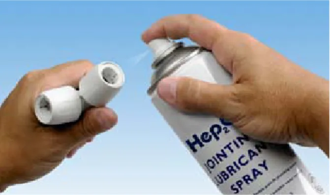
All O-ring seals contained in Hep2O fittings have been
pre-lubricated during factory assembly and during normal installation additional lubrication should not be required. If the fitting has been used previously then the lubricant may have been removed and may require replacing. In these
situations Hep2O Jointing Lubricant Spray (code HX200) must
be used to avoid contravention of Water By-laws and ensure
compatibility with other system materials (see Fig. 9).
Don’t use other manufacturer's lubricant or any alternative.
Fig. 8 Hep2O 15mm assembly with pipe markings
Jointing with Hep
2O pipe and fittings
SmartSleeve™ pipe support sleeve
Before making a joint using Hep2O pipe, it is essential to insert
a Hep2O SmartSleeve™ pipe support sleeve into the cut pipe
end (see Fig. 10). The only exception is when connecting to the open spigot end of a Hep2O fitting.
The SmartSleeve™ has several purposes:
• It ensures the pipe retains its circular cross-section.
• It eases insertion of the pipe into the fitting.
• The profiled end of the SmartSleeve™ helps you to check
the pipe is fully inserted. See In4Sure™ joint recognition
technology (see page 15).
• It maintains the rigidity of the pipe within the fitting.
• It retains the circular cross-section of the pipe under extreme
temperatures.
• Barbs on the SmartSleeve™ lock it in the pipe, which helps
ensure it is not left in the fitting when demounting. All SmartSleeve™ pipe inserts are manufactured from ‘food quality’ 316 stainless steel and are impervious to contaminants. They are designed to be captive in the pipe but can be removed if required, using long nosed pliers. However, if damaged, the
SmartSleeve™ must not be re-used.
Jointing procedure
Whichever type of Hep2O fitting is used, the same jointing
procedure should be followed.
1. Cut the pipe squarely at one of the ‘
^
’ marks using recommended pipe cutters and ensure the pipe end is free from burrs (see page 10).2. Insert a Hep2O SmartSleeve™ pipe support sleeve into the pipe end.
3. Push the pipe firmly into the fitting, then
use Hep2O’s unique
In4Sure™ joint recognition technology to ‘feel’ if the pipe is fully inserted (see page 15).
4. Tug back on the pipe to
ensure the grab-ring engages correctly and prevents the pipe withdrawing.
Jointing copper pipe to Hep
2O fittings
Hep2O fittings have been designed to form reliable joints with
metric copper pipe which conforms to BS EN 1057 - R520.
1. Measure the pipe, allowing sufficient length for insertion
into the fitting, and mark with a pencil (see Table No.2).
2. Cut the copper pipe with a wheel cutter.
3. Carefully inspect the pipe ends for burrs or swarf.
4.Push the pipe firmly into the fitting.
5.Tug back on the pipe to ensure the grab-ring engages
correctly and prevents the pipe withdrawing.
With a little extra care, it is also possible to connect 10mm
BS EN 1057 - R220 copper pipe into Hep2O fittings.
R220 pipe is particularly ‘soft’ and therefore susceptible to becoming misshaped or dented if it is not handled with care. Particular attention should be paid to the cut end, looking for any signs of damage. R220 copper pipe should be cut with a mini wheel cutter, and then a chamfer should be filed on the pipe and any copper filings rinsed away, and the pipe dried-off.
Hep2O can also be connected to ¾" Imperial copper pipe using
a special O-ring straight adaptor (HX3A/22) which accepts
22mm copper pipe at one end and ¾" Imperial copper pipe at the other.
Note:
New pipe insert for copper providing joint recognition will be available soon.
Fig. 12 Hep2O fittings
are also compatible with copper pipe
Fig. 13 HX3A/22 3/ 4"
Checking the joint using In4Sure
™joint
recognition technology
Follow normal procedure to establish the insertion depth of
the pipe into the fitting as previously described (see page 13).
In4Sure™ joint recognition technology then provides a further check by allowing you to ‘feel’ if the pipe is fully inserted.
To use In4Sure™ joint recognition technology:
1. Hold the centre (fixed) part of the fitting in one hand.
2. After inserting the appropriate pipe sleeve, push the pipe
firmly into the fitting.
3. While still pushing, rotate the pipe using a screwing
action. If the pipe is fully inserted you will feel a ‘rumbling’
sensation as the profiled end of the SmartSleeve™ passes
over the castellated seat inside the fitting.
4.Pull back to check the joint integrity.
This simple procedure is designed to give you the peace of mind that comes from knowing that the joint is good. You can
also make a visual check by checking the next ‘
^
’ mark islevel with the end of the fitting.
Fig. 14 Cut-away showing In4Sure™ joint recognitiontechnology
Demounting joints using the Hep
2O
HepKey
™system
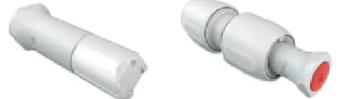
Two types of HepKey™ are available:
• HepKeyPlus™ simply clips onto the fitting and holds the grab-ring in its release position.
• The HepKey™ is small enough to be kept in your pocket.
Both types are colour-coded: 10 green, 15 blue, 22 purple
and 28mm orange.
Whichever type of Hep2O fitting is used, the same demounting
procedure should be followed.
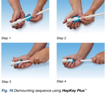
To use HepKey Plus™:
1. Place the HepKey Plus™ around the pipe
2. Clip HepKey Plus™ over the fitting
3. In this position it depresses the inner release ring of the fitting.
4.Withdraw the pipe from the fitting.
Fig. 15HepKeyPlus™ Fig. 16HepKey™
To use HepKey™:
1. Clip the HepKey™ round the pipe next to the joint to
be demounted, with the flat side of the HepKey™ away
from the fitting.
2. Slide the HepKey™ up to the fitting and press so that the protruding 'lugs' depress the inner release ring of the fitting.
3. Withdraw the pipe from the fitting.
Note:
Before re-using the fitting we recommend applying a small amount of Jointing Lubricant Spray (code HX200) to the O-ring seal inside the fitting (see page 11).
Step 1 Step 2
Step 4 Step 3
Fig. 18 Demounting sequence using HepKeyPlus™
Hints and tips for trouble-free
Hep
2O installation
These are simple and effective precautionary steps which should be taken to avoid problems and ensure trouble free installation of Hep2O.
Hep2O pipe
The biggest potential problem is damage to a pipe end, in the form of a deep scratch which can create a leak pathway for water to pass. Taking a few precautionary measures can eradicate any such problems.
• Take care how and where the pipe is stored.
• Retain pipe in protective packaging until it is to be used.
• Never use an open bladed knife to remove the
pipe packaging.
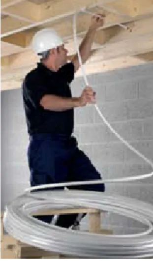
• In the case of coiled pipe, always use the shielded blade tool
supplied (see Fig. 20) to slit the packaging around the inside of the coil. This enables the pipe to be drawn from the inside. The packaging then serves to contain the coiled pipe until the last metre (see Fig. 21).
• When threading pipe through holes in stone, brick or block
walls always use a pipe sleeve or a small piece of foam pipe insulation to protect the pipe from the rough surface.
• Ensure exposed first fix pipe ends are protected from
damage by using a temporary end protector. This also ensures no debris will enter the pipe (see Fig. 22).
• Avoid kinking the pipe during installation.
Fig. 20 Unwrapping coil
Fig. 22 Always protect pipe ends
Fig. 21 Packaging retains pipe until last metre
Hep2O fittings
As the fitting cannot be taken apart few problems can arise but some basic precautions are advisable.
• Avoid dust and debris entering the fitting.
• Store materials in a secure place free from dust and dirt etc. • Keep fittings in their bags until ready for use.
• When re-using a fitting, spray a little Hep2O HX200 Jointing
Lubricant onto the O-ring (see Fig. 9 on page 11).
Handling and storage
Hep2O is an extremely tough and durable system.
However, following the simple guidelines below will ensure its performance is not impaired by poor storage.
• Straight lengths of Hep2O pipe should be stored flat or
stacked vertically.
• Coils may be laid on their side or edge.
• Pipe and fittings, wherever possible, should be stored in their
original packaging. This ensures protection from ultra violet light and reduces the risk of contamination.
• All Hep2O pipe and fittings should be protected from contact
with petroleum and oil derivatives.
• Avoid dragging the pipe along the ground or on other
surfaces such as walls.
• When feeding pipe through holes in walls and brickwork pipe
ends should be taped over, or an end cap should be used. These precautions will protect the pipe end from damage and also prevent debris entering the pipe.
• Care should be taken to avoid kinking the pipe
Colour-coded packaging
To make buying, handling, storing and installing the Hep2O
system as simple as possible, a colour-coded system has been introduced.
Hep2O fittings are now supplied in sealed polythene bags
colour-coded by size, which makes them easy to keep clean and easier to identify – you can see all the 15mm fittings at a glance – just look for the blue packs.
Just to make it easier still, the same colour-coded packaging
has also been applied to Hep2O pipe.
• 10mm: green
• 15mm: blue
• 22mm: purple
• 28mm: orange
No more searching the van to find those elusive 22mm elbows, just look for the purple bag!
Fig. 23 Colour-coded packaging is designed to make product selection easier
Connecting Hep
2O pipe to compression fittings
Hep2O pipe is suitable for connecting to compression fittings
which comply with BS EN 1254.
Cut the Hep2O pipe with the recommended cutters and
proceed as follows:
1. Cut pipe and insert a Hep2O SmartSleeve™ pipe support
sleeve into the pipe end.
2. Apply PTFE tape if required.
3. Fully insert the pipe into the fitting.
4. Tighten nut, taking care not to over-tighten.
Note:
• Do not use oil based jointing compounds • Always use an appropriate SmartSleeve™ pipe
support sleeve
• Use copper olives in preference to brass • Hep2O pipe will not rotate in a compression
fitting after tightening
Insert support sleeve into pipe
Ensure pipe is fully inserted
Apply PTFE tape if required
Tighten nut
Fig. 24 Procedure for connecting Hep2O pipe to a
Hep
2O connections adjacent to capillary joints
When using Hep2O pipe or fittings adjacent to capillary joints,
soldering work should be carried out before the Hep2O
is installed. If this is not possible, keep any heat away
from Hep2O and observe the following precautions:
1. Don’t allow Flux to run onto Hep2O pipe or fittings. Flux runs
inside the pipe may occur during soldering, this effect can be reduced by not using excessive amounts of Flux and by applying Flux to copper pipe end only.
2. Don’t allow hot solder to come into contact with Hep2O.
3. Don’t allow Hep2O to overheat. Wrap a damp cloth around
copper pipe to minimise any likely heat transfer or use a heat absorbing gel.
Note:
Systems should be flushed with water to remove any internal Flux residues.
Connection to chrome plated or stainless
steel pipe
Hep2O fittings cannot be connected directly to chrome plated
copper or stainless steel, because of the relative surface hardness of these materials. The recommended method is to
use compression fitting (see page 21).
Connection to brass spigots
The only brass spigots suitable for jointing into Hep2O fittings
are those included within the Hep2O range. Brass spigots
designed for compression or capillary joints do not have the necessary joint grooves and are too short.
Connection to earlier Hep
2O systems
Hep2O is fully compatible with all current and earlier versions
of Hep2O fittings, including its immediate predecessor and the
earlier Acorn® system manufactured by Bartol.
Pre-1984 Acorn® 22mm pipe was manufactured with a
thicker wall and requires a different pipe support sleeve. If carrying out remedial work on such a system please
Connecting Hep
2O fittings to other brands
of pipe
Hep2O fittings should not be used in conjunction with other
manufacturers’ plastic pipe and fittings, as dimensional tolerances and quality control cannot be guaranteed by Wavin.
Connecting Hep
2O to steel pipes and
threaded bosses
In order to facilitate connection to male and female iron threads,
four adaptors (HX28/HX29 socket adaptors) and (HX31/HX30
spigot adaptors) are available in the Hep2O range. This enables
connection to a wide range of different materials.
HX28 Socket adaptor HX29 Socket adaptor
HX30 Spigot adaptor HX31 Spigot adaptor
Connections to appliances using Hep
2O
When connecting to appliances and dishwashers always use
Hep2O appliance valves from the Hep2O range (HX38/15).
Adjacent Hep2O pipework should be clipped in accordance
with the recommended clipping distances using screw-type
clips (HX85) (see pipe support - page 29).
System alterations
Using a Blanking peg to seal off a fitting
When you need to provide a temporary or permanent seal to one of the ports on a Hep2O fitting, insert a blanking
plug (HX44) directly into the open connection. You can use
In4Sure™ joint recognition technology to check the plug is
fully inserted. To remove the plug use a HepKey™ or HepKey
Plus™ and continue with the installation.
Using a stop end to seal off a pipe
When you need to close off the open end of a pipe,
first fit a SmartSleeve™ support sleeve in to the open pipe
end then fit a stop end (HX62) onto the pipe to provide
a temporary or permanent seal.
HX30 Spigot adaptor
Fig. 25 Valves for connecting appliances
Fig. 26 Blanking peg shown on its own, and inserted into fitting
Where it’s OK to use Hep
2O
Hep2O is suitable for most domestic and commercial
hot/cold water and heating applications. A comprehensive range of fittings meets all today’s requirements and provides secure connection and reliable operation. Providing installation work has been carried out using good plumbing practice as outlined in this guide, all Hep2O pipe and fittings are
guaranteed for 50 years under normal use.
Where it’s not OK to use Hep
2O
The Hep2O system has been designed and tested to meet
the requirements of modern heating and water distribution systems.
Testing has not been carried out to determine suitability for
other purposes and therefore Hep2O should not be used in
the following applications:
• Conveyance of gas
• Conveyance of fuel oil
• In areas contaminated by petroleum and oil derivatives
• Conveyance of compressed air
• Hep2O is not suitable for use in systems where the water
carried in the pipe contains a high concentration of chlorine e.g. swimming pools or decorative water features
• Hep2O will not be affected by those levels of chlorine
expected in the UK water supply (typically less than 0.5ppm).
Short term chlorination for disinfection will not have an
adverse effect on the system (see page 51).
• Hep2O should not be used for the primary circuit of a
Solar Heating System as temperature cannot be
thermostatically controlled. Hep2O is suitable for secondary
circulation of these systems.
• Hep2O should be protected at all times from exposure
to direct sunlight and ultra violet light.
•Hep2O should not be installed in Continuously operated re-circulating systems (Secondary Hot Water Circulation / Ring main installations). Please see Important
Information section on page 51 for more details. Fig. 28 New Hep2O is now more compatible with modern
Cabling through joists
The Building Regulations Approved Document A allows for pipework to be installed in joists by either notching or drilling. The traditional method has been to notch the joists as the rigidity of the pipe does not easily allow for any other method of installation. However this has a number of disadvantages:
• Pipework must be installed prior to the floorboards
being laid.
• Plumber has to work on open joists increasing risk
of accident.
• Need to return after floors are laid to connect radiators, etc.
• Tails often moved by other tradesmen, causing extra work to
reposition pipework correctly for radiators.
The exceptional flexibility of Hep2O pipe removes most of
these restrictions by allowing pipe to be easily curved and ‘cabled’ through drilled joists, or I-beams which means:
• Flooring can be laid prior to the plumber carcassing
from below which will progress the building schedule as other trades can work on the floor above e.g. to form studwork etc.
• Site safety enhanced as the plumber is not exposed to the
danger of falling or the discomfort of kneeling on open joists.
• Other trades working below are protected from the dangers
of falling tools, molten solder, gas bottles etc.
• Carcassing at a later stage in the construction programme
means the building is likely to be weatherproof.
• Less danger of puncturing the pipe with nails used for fixing
the floorboards and no need to use protective devices such as ‘joist clips’.
It is worth noting that drilled holes in joists should be large enough to allow for thermal movement of the pipe.
Fig. 29 Hep2O speeds up installations because pipework can be easily cabled through drilled joists
Less risk to health and greater site safety
The unique Hep2O system ensures:
• Effective, leak-free pipe jointing without the use of a naked flame.
• No soldering means safety from fire, especially
in restricted spaces.
• Improved working environment.
• No Flux or Solder eliminates potential contamination
of water supplies.
Hep2O push-fit jointing also has the following advantages:
• No naked flame means that precautions such as obtaining
a ‘Hot Work’ permit, having a fire extinguisher readily available, and remaining on site for a while after jointing, are not necessary.
• No risk of infringement of Health and Safety
recommendations applicable to some brands of Flux. e.g. means to control exposure to noxious fumes when working in a confined space, and use of eye protection (where appropriate).
• After jointing, the fitting is clean and safe to touch, e.g. after soldering, the joint is hot and Flux traces need to be removed.
• Joint is rotatable after installation.
Other system benefits include:
• Longer pipe runs and less joints, due to pipe flexibility.
• Elimination of ‘dry runs’ as pipe can be cut and jointed
in situ.
• Absence of solvents means testing can be carried out as
soon as installation is complete.
• Tails for connection to sanitary ware can be left long enough
for final connection, thus eliminating the need for straight and offset connectors as with rigid pipe systems.
• Natural flexibility of the pipe helps overcome small misalignments.
Drilling the floor joists
• Hole diameters should be no greater than 0.25 of the depth
of the joist and should be drilled at the neutral axis.
• They should be not less than 3 diameters (centre to centre)
apart and should be located between 0.25 and 0.4 times the span from the support.
Note:
The Building Regulations Approved Document A gives exact instructions on the drilling of floor joists.
These points are illustrated (see Fig. 30).
The value 0.25 is obviously one quarter and can easily be calculated on site. The value 0.4 is less obvious and can be obtained (see Fig. 31).
Note:
The minimum distance between a hole and a notch in the same joist should not be less than 100mm.
Note:
This graph should be used in conjunction with Fig. 30. Example of use: Joist span is 4.5m.
Find value on horizontal scale and read up to sloping line. Transfer point of intersection to the vertical scale and read 1.8m.
Fig. 30 Explanation of drilling joists in accordance with the Building Regulations Approved Document A
HOLES SHOULD BE LOCATED IN THIS ZONE & DRILLED AT THE NEUTRAL AXIS.
CENTRAL AXIS OF JOIST SPAN ‘S’
NOT LESS THAN 3 DIAMETERS APART CENTRE TO CENTRE. MAX. DIAMETERS OF HOLES =
0.25 X DEPTH OF JOIST.
DEPTH. 0.4 x ‘S’
0.25 x ‘S’
Fig. 31 Graph showing dimension of joist drilling zone from support 1.5 0.5 1.0 1.5 2.0 2.0 2.5 3.0 3.5 Span of joist (m)
Maximum Distance from Support
Distance from Support (m)
Minimum Distance from Support
Engineered joists
Hep2O is ideal in buildings incorporating timber ‘I’ joists.
Piping can be properly installed through holes in the web
section without damaging flange members (eg. TJI Joist
system, Truss Joist MacMillan Ltd.) even where the pre-formed holes do not align on the plan.
Spigot tees and manifolds
The Hep2O system incorporates a comprehensive range of
spigot tees which can be used individually or in groups to give manifold arrangements with the benefit of 360° rotation. Alternatively, the system includes a selection of manifolds from single to four ports (see page 47).
Connecting pumps, valves etc:
Where Hep2O is connected to pumps, valves and similar
devices consideration should be given to adequately
supporting the item in question (bearing in mind the rotatability
of the Hep2O joint). Equipment should not be suspended from
the pipe without adequate support.
Pipe support
The Hep2O system includes two types of pipe clip - the screw
fix type (HX85) and the nail type (HX65).
Code Nominal Diameter HX65/10 10 HX65/15 15 HX65/22 22 HX65/28 28 Nail Screw Spacer
Code Nominal Diameter HX85/15 15
HX85/22 22 HX85/28 28
Code Nominal Diameter HX86/15 15
HX86/22 22 Note:
The HX86/22 spacer can be used with both the HX85/22 and HX85/28 clip. Fig. 32 Pipe clips
The nail type is designed for use on concealed pipework for rapid fixing to timber. The screw type may be used together
with a spacer (HX86) to allow greater spacing between the
pipe and the fixing background. The spacer therefore allows different pipe fixing centres which can be used to facilitate pipe cross-overs or fitting of thermal insulation to the pipe.
Note:
A cold forming bend fixture (HX75) is also available to allow
the formation of a bend on 15mm and 22mm pipes for situations where secure fixing and neatness are important.
Fig. 33 Pipe fixing centres
Fig. 34Cold forming bend fixture radii
Pipe Clip Pipe Clip and Spacer
Fixing hole size is 5mm. Suitable for a No. 10 woodscrew Fixing hole size is 5mm diameter.
Nominal Diameter Dimension A Dimension B
mm mm mm
15 17 40
22 21 43
28 24 46
Nominal Diameter mm Radius A mm
15 120
Cable ties
When pipe is concealed, cable ties may be used for support instead of clips. However these should not be over-tightened. The pipe should be allowed to slide freely to allow for thermal movement.
Pipe support distances
The recommended support distances for general purpose use are shown in Table No. 3.
Where piping is adequately supported or is run within
concealed spaces (e.g. through suspended timber floors)
clips can be reduced or omitted provided that:
• Pipe does not form part of an open vent provided for safe
operation of a heat source.
• Pipe does not form a distribution pipe or circuit where
effective air venting might be impaired by poor pipe alignment.
• Hot pipe will not come into contact with cold pipe
or vice versa.
• There is no risk that pipes or fittings will come in contact with sharp, abrasive or other potentially damaging surfaces.
• There is no risk pipe will come in contact with materials
which may be affected by transmitted heat.
Where pipe is visible, a support distance between fixings of 300mm is suggested.
Where provision has been made for electrical wiring, such as in some partition systems, this can often be utilised for Hep2O pipework.
Table No. 3Recommended clipping distances
Nominal Diameter Horizontal Runs Vertical Runs
mm m m
10 0.3 0.5
15 0.3 0.5
22 0.5 0.8
Minimum bending radius for Hep
2O pipe
Nominal Diameter mm 10 15 16 20 22 28 A mm 80 120 128 160 176 224 Fig. 35Minimum bending radii (8x pipe diameter)
Fig. 34 shows a cold formed bend fixture (HX75). This is
suitable for use with 15mm or 22mm where secure fixing and neatness are important.
Hep2O pipe can easily be manipulated by hand to form bends
of any angle. In order to prevent any long term detrimental
effect on the material, the curvature of Hep2O pipe should
be not less than that shown. A bending radius of 8x the pipe diameter is the minimum allowed.
Pipework installation
Hep2O fittings are now much sleeker and more stylish than
previously, making them a lot more acceptable for exposed locations.
However, Hep2O pipe expands as temperature increases,
causing it to undulate along its length and this effect is sometimes exacerbated where it is ‘cabled’ through joists. This will not create airlocks or have any other adverse effect on the operation of the plumbed system.
Concealed locations
Hep2O pipe is relatively easy to install in concealed locations
in floors, roof spaces etc. Any expansion in the pipe will have little mechanical effect, this being absorbed within the pipe length so undulation can be ignored.
Installation in difficult locations is aided by the cabling
ability of Hep2O pipe. If adequately supported, Hep2O pipe
in concealed locations need only be clipped for system alignment e.g. at changes in direction. If preferred, cable ties can be used in such areas.
Use of metal tape to aid ‘electronic’ pipe detection
The NHBC Standards includes a section which affects the installation of pipework in walls. It states:
‘Where pipework is in or behind wall surfaces, and would otherwise not be detected by a metal detector or similar equipment, a metallic tape should be applied to the pipework’. The NHBC has agreed that other methods of installing tape are also acceptable, as any tape applied to plastic pipe or fittings will require testing to ensure compatibility with the pipe and ensure the adhesive will not pass through the pipe and taint the water.
Note:
Metallic tape with an adhesive backing should NOT be applied directly to Hep2O pipe and fittings, but the following methods of aiding detection are allowed:
Metallic tape without adhesive can be lightly crimped around the pipe to allow detection by an electronic pipe detector or, adhesive metallic tape can be stuck to the backing wall as close as possible to the pipe run.
Fig. 36Metallic tape can be used to aid electronic pipe detection
Pipes through walls and floors
Wherever Hep2O pipe passes through brickwork, stone or
concrete it should be sleeved. The annular gap between the pipe and the sleeve should be filled with a resilient material to provide an effective fire stop and also prevent the transmission of noise from one room to another.
Expanding foam, in its initial wet state, must not come into
contact with the Hep2O pipe as it can cause an adverse
chemical reaction whilst drying. The use of a pipe sleeve will provide the necessary protection.
Laying pipe in floor screeds
Unlike metal pipes, Hep2O is not affected by the corrosive
effects of cement, lime, mortar or concrete. However, account should be taken of the Water Byelaws which requires distribution pipework to be accessible to facilitate its removal
and replacement (see page 35 Hep2O Conduit system).
Pipes adjacent to metalwork
When running Hep2O adjacent to or ‘through’ metalwork, it is
important to ensure that the pipe doesn’t come into contact with any sharp edges as any subsequent thermal movement could cause damage.
The following cautionary measures should be observed:
• Where pipe passes through a small drilled hole, fit a
suitable grommet
• Where pipe passes through a large hole in metalwork
or adjacent to a sharp edge, fix an extruded flexible profile to the metalwork
• Provide adequate pipe clips or cable ties to prevent
abrasive contact between pipe and metalwork
• Run the pipe within a conduit
Hep2O pipe means quieter operation because there’s
less noise…
Problems with noise are often found in systems which
incorporate rigid pipes. Hep2O pipe does not transmit
noise and with careful installation, can be installed to run almost silently.
…from friction
Noise can be caused by friction between a pipe and adjacent surfaces – typically where rigid pipes are installed beneath timber or chipboard flooring.
Hep2O can greatly reduce this effect. Where holes are drilled
through joists they should be of sufficient diameter to allow Hep2O pipe to slide freely (see page 26). This will prevent any
friction between the underside of a floor, and more importantly, it will avoid the ‘ticking’ and creaking normally associated with the thermal movement of rigid pipes
…from knocking
Noise can be caused by rigid pipes knocking together or
knocking on adjacent surfaces. Hep2O’s inherent elasticity
cushions such impact, causing less impact noise and absorbing vibration, thus preventing the transmission of sound along the pipe.
…and from ‘water hammer’
Similarly noise from ‘water hammer’ resulting from abrupt
stoppage of water flow (typically by closure of quarter turn
valves, solenoids and reverberating ball valves). Such noise
is normally absorbed by Hep2O and is not transmitted along
the pipes.
Installing pipes in concrete floors or walls
Hep2O Conduit system
The Hep2O Conduit system allows pipe and fittings to be
installed directly into concrete floors or into walls whilst complying with the requirements of the Water Regulations.
The flexible conduit allows Hep2O pipe to be easily
withdrawn for inspection, and junction boxes allow maximum accessibility to fittings for inspection and possible removal. If any bent sections of conduit pipe are formed in an installation then future replacement of the Hep2O is likely
to require the use of a ‘draw cable’. This requires a cable to
be attached to one end of the Hep2O pipe before it is pulled
out of the conduit from the other end. The draw cable remains in the conduit. Subsequent replacement of a new section of
Hep2O pipe may require two operatives; one pulling the draw
cable which is attached to the pipe end, and the other person feeding-in the new length from the opposite end. Future replacement will be easier if conduit bends are kept to a minimum and any radius kept as large as practicable. See also ‘Fitting the conduit’, later in this section.
The system is available in all diameters, together with junction boxes with lids and terminal fittings.
Holes can be cut in the sides of the junction box at the appropriate position to accommodate the conduit which simply clicks into position.
Installation
The Hep2O pipe should be fed into position at the same time
as the conduit system is installed, i.e. before screeding. The conduit system should not be installed on sub-floors a long time in advance of screeding as damage by site traffic could occur. The junction box allows access to pipe
fittings, and also allows pipe cross-overs (which are normally
undesirable within the floor screed material).
Dimensions are shown (see Fig. 39).
The conduit pipe should be fixed to the sub-floor using suitable straps to prevent movement. Conduit pipes for cold water systems should not be run in floor screeds which incorporate underfloor heating loops. If required the junction box can be cut in half and installed up against a wall (see Fig. 40).
Fig. 39Junction box dimensions
Plan
Side section
End section
Fig. 37 Conduit junction box Fig. 38 Cut conduit box for wall termination
Installation continued
The junction box should be drilled using a hole cutter or spade bit, to allow the conduit to fit snugly and click into position.
It should protrude at least 5mm inside the box. Hole sizes and conduit OD’s are shown in Table No. 4.
Table No. 4 Drill size for conduit box holes
Hep2O Size Conduit Code Conduit
(mm) OD (mm)
10 & 15 HXC25/15 - HXC50/15 - HXXC50/10 - HXXC50/15 25 22 HXC25/22 - HXC50/22 - HXXC50/22 34
28 HXXC25/28 42
Note:
Central heating pipework should not be run within the same junction box as cold water pipework unless there is space to fix adequate thermal insulation to prevent the warming of the cold water. The prevention of cold water becoming warm is a Water Regulations requirement.
Hep2O pipe to radiator or sanitary appliance Junction box lid
Junction box cut in half and secured to sub floor Fig. 40Cut junction box
Fitting a junction box
The junction box should be fixed to the sub-floor to prevent movement during screeding. Fixings with suitable washers should be used and the box should be positioned so that the lid (when fitted) will be level with the adjacent final floor finish. If the required screed depth exceeds that of the junction box, suitable packing should be placed under the base.
However, if the junction box is to be installed into insulation, there is no effective method of holding the box down, so double sided adhesive tape should be used.
Note:
Thermal pipe insulation is not necessary when the junction box is used solely for central heating pipes.
Fig. 41Hot and cold water distribution pipes at tees
Finished floor level
Junction box lid, drilled and secured by fixing screws
Small insulating pad, cut and placed to separate pipes at cross-over
Thermal insulation barrier formed across junction box (if necessary).
Conduit
pipe Junction box secured to the sub-floor
Tee on cold
Fitting pipe into conduit
To facilitate the possible removal and replacement of Hep2O,
the conduit should be installed without joints and should ideally run in straight lines between junction boxes. Where bends are unavoidable, there should not be more than two changes of direction between adjacent junction boxes.
• Conduit carrying cold water pipes should not touch conduit
carrying hot water or central heating pipes.
• When running conduit within floor screeds the recommended
gap between hot and cold should not be less than 50mm
in order to prevent the warming of cold water (see Fig. 42).
• The conduit system should not contain unused water pipes
which remain connected to water systems. Redundant pipework will result in water stagnation which would pose a risk to health.
Fig. 42Spacing for cold water conduit in floor screeds
Terminating the conduit
For terminating the conduit pipe at wall and floor finish level for direct 15mm connections to appliances, a conduit terminal fitting is available (HX101/15). For floor terminations the plastic housing may be drilled through the base to allow fixing.
Floor termination procedure (see Fig. 45).
Fig. 43 HX101/15 15mm conduit terminal
Fig. 45HX101/15 conduit terminal installation procedure
Fig. 44 HX103 terminal back plate
Terminating the conduit continued
For wall terminations the HX103 terminal back plate can
be used to mount two terminals side by side (see Figs. 44
and 46) or it can be easily split to form two single plates. The same terminal back plate can also be used to fix a
maximum of four wall plate elbows (see Fig. 47).
Fig. 47HX103, terminal back plate and HX6/15 wall plate elbow
Fig. 48Installation of HX102 terminal fitting plate and HX101/15, 15mm conduit terminal
Fig. 46HX101/15, 15mm conduit terminal and HX103 terminal back plate
Hep
2O Pipe-in-Pipe system
This consists of Hep2O Barrier pipe (see page 9) pre-sheathed
in conduit ready for underscreed installation.
This saves time and effort whilst complying with the current
regulations. Hep2O Pipe-in-Pipe is available in manageable
coil lengths, and the conduit is available in red and blue to aid identification.
Fig. 49Hep2O Pipe-in-Pipe is supplied in coils with a choice of
Dry lined wall feeds for radiators
There are distinct advantages to using 10mm Hep2O pipe
instead of microbore copper feeds to radiators. Hep2O
pipe can easily be accommodated behind ‘dot and dab’
plasterboard (see Hep2O within internal drywall system on
page 48) to give a pipe-free appearance within a room, but unlike copper, it is not susceptible to damage such as dents or kinks which can be caused on ‘soft’ copper by other follow-on trades.
Radiator outlet cover plate
A neat solution when using 10mm Hep2O pipe, is to utilise the
HX113 Hep2O Radiator Outlet Cover Plate. This cover plate,
fitted in conjunction with a back box provides an exceptionally neat and easy to install method of connecting radiators. It also has the benefit of a hinged flap that provides an airtight seal. The box is fixed in a central position behind the radiator with the 10mm pipes dropping out to the radiator valves. This gives a smart professional finish where little or no pipe is seen and for new build provides an anchor point for the pipework prior
to plastering/boarding (see Fig. 51 on page 44).
Fig. 50Radiator pipework in 10mm Hep2O within dry lined walls
Thermostatic radiator valve Pipe clip (HX84/10) 90° Elbow (HD5/10) 90° spigot elbow (HD4/10) Skirting board Radiator draincock 90° spigot elbow (HD4/10)
First-fix radiator feeds
The following is good practice for first-fix pipework:
• For conventional connections to radiators, the pipe
drops should run vertically, side by side at one end of the radiator position.
• Where a radiator outlet cover plate is used, the radiator
drops should run vertically, side by side, to the centre of the radiator position.
• Lateral pipes should be run horizontally through the
stud work, avoiding any obvious fixing zones such as skirting boards.
Note:
Where subsequent wall fixings are likely, metallic tape should be used to enable an electronic pipe detector to be used (see page 33).
For fixing pipework to lightweight blockwork, use wooden dowels at each clip position. The HX65 pipe clip is not suitable for fixing directly to such walls because of the low pull-out resistance of the nail.
Fig. 51 Installation procedure of HX113 cover plate
1. Position back box centrally behind radiator location with adequate pipe for left or right connection
2. Fit cover plate which provides an airtight seal when closed
3. Pipework can now be left until follow-on trades have finished working
4. The result leaves little or no pipe on show
Connecting Hep
2O pipe to storage vessels
and radiators
Although Hep2O pipe is compatible with most other makes
of fittings, when connecting it to cylinders, radiators etc.
Hep2O fittings should be used wherever possible. If an
appropriate fitting is not available from the Hep2O range,
a recognised brand should be used.
The Hep2O range includes double check valves, tank
connectors, gate valves, stopcocks and cylinder connectors. If the use of compression fittings is unavoidable then the jointing instructions outlined in the section, ‘Connection
Using Compression Fittings’ (see page 21) should be
carefully followed. Also:
• Do not use any jointing compound on the jointing shoulder
of the cylinder connector, use only PTFE tape.
• Do not use any jointing compound when fitting tank
connectors, use only sealing washers.
Connecting Hep
2O to ancillaries
(pumps, valves, etc.)
When connecting Hep2O to ancillary items, it is important
to follow the guidance in the section ‘Connections Using
Compression Fittings’ (see page 21).
Hep2O pipework must be clipped adjacent to the outlets of
the pumps and valves using Hep2O screw pipe clips (code
HX85). This ensures adequate support and reduces vibration in the majority of cases. Where it is felt that the weight of the connected equipment merits extra support, metal brackets should be used. Where the size of the pump and/or valve requires fixing at a greater distance from the wall than can be accommodated by the pipe clip alone, this can be augmented with a pipe spacer (HX86). This will allow a greater ‘stand-off’ distance whilst maintaining security.
Connecting boilers and heaters
Where boilers incorporate a high limit cut out thermostat, pump overrun device and have connections outside the boiler casing 350mm from the heat source, direct connection can be
made using Hep2O. Typically these boilers contain a copper
heat exchanger and are low water content boilers. Where the above criteria for direct connection to a boiler cannot be met a minimum one metre run of copper pipe should be installed between the boiler and the start of the
Hep2O system.
Note:
Where individual boiler manufacturers instructions state differently, they should always be followed.
In all cases including instantaneous water heaters, caravan heaters etc. care must be taken to ensure that appliances have the appropriate thermostatic controls and cut outs to ensure that operating conditions do not exceed the temperature and pressure limits laid down for Class S pipe. (see Table No.1 - page 7).
For any type of back boiler, all the water connections should be extended from the appliance to the outside of the fireplace opening using copper pipe.
Any gravity circuit of a solid fuel boiler should always be installed in copper. Regulations require that metal pipe be used as the discharge pipe from temperature/pressure relief valves on unvented water heaters, to or from a tundish, or from safety valves on sealed central heating systems. On sealed systems where the safety valve is not provided within the boiler casing, the pipe between the safety valve and the boiler should be in copper. All boiler connections should be made in accordance with the requirements of
BS 5955, part 8.
Note:
During commissioning it is important to ensure that all trapped air is purged from the heating system before the boiler is operated. ‘Pockets’ of air can effect proper circulation and impair the correct operation of boiler temperature controls, and this can cause severe overheating.
Manifolds
Hep2O 10mm manifolds are particularly suited to microbore
plumbing and are available in 2 and 4 port versions. They are designed primarily for use in central heating systems but can
also be used for hot and cold water supplies. Hep2O 15mm
manifolds are available in 2 and 3 port versions.
A Hep2O manifold is a single fitting which brings together
multiples of 10mm or 15mm pipe, on the flow or return pipework, to one area of a building, enabling easy access.
A comprehensive range of Hep2O manifolds is available,
and these can be connected in series to allow any number of outlets. Alternatively, a range of ‘spigot tee’ fittings can be coupled together to give independent 360° joint rotation.
Fig. 53 Hep2O manifolds are used to connect multiples of 10mm or 15mm pipe
Installation and performance benefits
• Choice of 2, 3 or 4 port manifolds reduce the number
of fittings required to connect 22mm pipe to 10mm or 15mm pipe.
• Manifolds reduce the number of fittings required
and cut installation time.
• Manufactured from Polybutylene, an extremely robust
yet lightweight material, they are easy to install.
• Lightweight Polybutylene manifolds enable pipe to
be suspended between joists without fear of it being dragged down.
• Hep2O blanking pegs can be used to close off any
unused sockets.
Hep
2O within internal drywall systems
The Hep2O system can easily be cabled within timber
studwork and within wall systems (eg. Paramount Board)
during construction. This method is often used for running feeds to radiators or where concealed plumbing is necessary, e.g. supplies to a recessed shower mixer.
A connection for a radiator can be made by using a secured elbow in the wall and fixing a plastic snap-on escutcheon to neatly cover the hole through the wall surface.
Alternatively for 10mm Hep2O a dry lining box can be used
which gives the advantage of allowing minor alignment adjustment to the ‘tail’ during ‘second-fix’ (see Fig 54) and allowing access to the elbow. ‘First-fix’ pipework should follow the good practice advice in the text headed ‘Dry lined wall feeds to radiators’ described above, and ‘pipes adjacent to
metalwork’ (see page 34).
Fig. 54Radiator connection using 10mm Hep2O and a dry lining box within a drywall
Note:
This solution can also be used where the radiator is fed from below in which case the risers should be located directly under each box.
10mm Hep2O
Dry lining box and cover plate (single gang electrical fitting) Demountable elbow (HD5/10) Non load-bearing internal drywall system
Hep
2O within timber framed and steel
framed buildings
The Hep2O system is ideal for use within both timber framed
and steel framed buildings but consideration must be given to:
1. Early detection of leaks which could damage the building
fabric if left unattended. Resultant repair delays would also contravene Water Bylaws.
2. Installation of the pipework which should be on the warm
side of any thermal insulation layer. It must also be possible to replace any pipes which pass through vapour control layers without affecting the integrity of the layer. To comply with the above, pipework should either be run within a recessed duct designed by the architect, or run within a conduit system. Whichever method is used it is necessary to consider the detail at the junction between the wall and floor to avoid floor joist problems and to agree pipe penetrations at header rails/bottom rails. For radiator connections, 10mm
Hep2O within conduit pipe may be used (see Fig. 55).
Fig. 55Radiator connection using 10mm Hep2O within timber or steel framed external wall Plasterboard When cutting vapour control plasterboard care should be taken not to displace vapour control material 10mm Hep2O 15mm (nominal) conduit pipe The conduit should be firmly terminated within dry lining box Demountable elbow (HD5/10) Dry lining box and cover plate (single gang electric fitting)
Insulating material
General advice
•For drilling holes through timber joists (see Figs. 30 and 31).
• Within steel framed buildings, pipework should be routed
through preformed holes in steelwork wherever practicable. No holes should be formed in steelwork without the approval of the architect. See text headed ‘Pipes adjacent to
metalwork’ (see page 34).
•Do not lay pipework in areas where plasterboard is likely to be fixed.
• Care should be taken to ensure pipework located within
compartments or passing through party walls or floors does not impair the fire rating of the building.
Fig. 56Installation is quicker and easier due to the flexibility of the Hep2O system