37441C
Manual
Software Version: 1.00xx or higher
Manual 37441C
DTSC-50
WARNING
Read this entire manual and all other publications pertaining to the work to be performed before in-stalling, operating, or servicing this equipment. Practice all plant and safety instructions and precau-tions. Failure to follow instructions can cause personal injury and/or property damage.
The engine, turbine, or other type of prime mover should be equipped with an overspeed
(overtemperature, or overpressure, where applicable) shutdown device(s), that operates totally inde-pendently of the prime mover control device(s) to protect against runaway or damage to the engine, turbine, or other type of prime mover with possible personal injury or loss of life should the mechani-cal-hydraulic governor(s) or electric control(s), the actuator(s), fuel control(s), the driving mecha-nism(s), the linkage(s), or the controlled device(s) fail.
Any unauthorized modifications to or use of this equipment outside its specified mechanical, electri-cal, or other operating limits may cause personal injury and/or property damage, including damage to the equipment. Any such unauthorized modifications: (i) constitute "misuse" and/or "negligence" with-in the meanwith-ing of the product warranty thereby excludwith-ing warranty coverage for any resultwith-ing damage, and (ii) invalidate product certifications or listings.
CAUTION
To prevent damage to a control system that uses an alternator or battery-charging device, make sure the charging device is turned off before disconnecting the battery from the system.
Electronic controls contain static-sensitive parts. Observe the following precautions to prevent dam-age to these parts.
• Discharge body static before handling the control (with power to the control turned off, contact a grounded surface and maintain contact while handling the control).
• Avoid all plastic, vinyl, and Styrofoam (except antistatic versions) around printed circuit boards.
• Do not touch the components or conductors on a printed circuit board with your hands or with conductive devices.
OUT-OF-DATE PUBLICATION
This publication may have been revised or updated since this copy was produced. To verify that you have the latest revision, be sure to check the Woodward website:
http://www.woodward.com/pubs/current.pdf
The revision level is shown at the bottom of the front cover after the publication number. The latest version of most publications is available at:
http://www.woodward.com/publications
If your publication is not there, please contact your customer service representative to get the latest copy.
Important definitions
WARNING
Indicates a potentially hazardous situation that, if not avoided, could result in death or serious injury.
CAUTION
Indicates a potentially hazardous situation that, if not avoided, could result in damage to equipment.
NOTE
Provides other helpful information that does not fall under the warning or caution categories.
Woodward reserves the right to update any portion of this publication at any time. Information provided by Woodward is believed to be correct and reliable. However, Woodward assumes no responsibility unless otherwise expressly undertaken.
© Woodward All Rights Reserved.
Revision History
Rev. Date Editor ChangeNEW 09-08-28 TE Release A 09-10-09 TE Minor corrections B 10-03-10 TE UL Certification C 12-04-10 TE Manual
• Minor corrections New device features & updates
Requirements: DTSC-50 ATS control with software version 1.0004 or higher and device revision B or higher. The described changes relate to the previous software version 1.0003.
New features
• Modbus protocol was implemented
Content
C
HAPTER1.
G
ENERALI
NFORMATION... 7
Related Documents ... 7
Overview ... 8
C
HAPTER2.
DTSC-50
O
VERVIEW... 10
C
HAPTER3.
E
LECTROSTATICD
ISCHARGEA
WARENESS... 11
C
HAPTER4.
H
OUSING... 12
Dimensions / Panel Cut-Out ... 12
Installation ... 13
C
HAPTER5.
W
IRINGD
IAGRAMS... 14
C
HAPTER6.
C
ONNECTIONS... 15
Terminal Arrangement ... 15
Power supply ... 16
Voltage Measuring ... 17
Voltage Measuring: Generator ... 18
Voltage Measuring: Mains ... 20
Discrete Inputs ... 22
Discrete Inputs: Bipolar Signals ... 22
Discrete Inputs: Operation Logic ... 23
Relay Outputs ... 24
Interfaces... 25
C
HAPTER7.
O
PERATION ANDN
AVIGATION... 27
Operation and Display ... 28
Purpose of the Status LEDs ... 28
Operating the DTSC-50 ... 28
Acknowledging Alarm Messages... 28
Configuring the DTSC-50 ... 29
Display of the Operating Values ... 29
Default Operating Value Display ... 30
Cycling Through the Displayed Operating Values ... 30
Alarm Messages ... 33
Configuration Displays ... 35
Display Hierarchy ... 37
C
HAPTER8.
F
UNCTIONALD
ESCRIPTION... 38
Overview ... 38
Operating Modes ... 39
Operating Mode STOP ... 39
Operating Mode MANUAL ... 40
Breaker Closure Limits ... 47
Generator Circuit Breaker... 47
Mains Circuit Breaker ... 47
Functional Description of the 2nd CB Close Delay Time ... 48
C
HAPTER9.
C
ONFIGURATION... 49
Restoring Default Values ... 49
Resetting Via the Front Panel ... 49
Resetting Via LeoPC1 ... 49
Configuration Via the Front Panel ... 49
Configuration Using the PC ... 50
Editing the Configuration File ... 51
C
HAPTER10.
P
ARAMETERS... 52
Measuring ... 53
Application ... 54
Engine ... 55
Engine: Start/Stop Automatic ... 55
Breaker ... 56
Emergency Power (AMF)... 57
Password ... 58
Monitoring ... 59
Monitoring: Generator ... 59
Monitoring: Generator Overfrequency ... 59
Monitoring: Generator Underfrequency ... 60
Monitoring: Generator Overvoltage ... 61
Monitoring: Generator Undervoltage ... 62
Monitoring: Mains ... 63
Monitoring: Mains Failure Limits ... 63
Monitoring: Engine Start Fail ... 66
Monitoring: Breakers ... 66
Monitoring: Engine Unintended Stop ... 67
Discrete Inputs ... 68 Relay Outputs ... 69 Counter ... 71 Communication Interfaces ... 73 System ... 74 Codes ... 74 Factory Settings ... 74
Parameter Access Level... 74
C
HAPTER11.
I
NTERFACES ANDP
ROTOCOLS... 76
Interfaces... 76
Service Port (RS-232/USB)... 76
Protocols ... 76
Modbus RTU Slave ... 76
Data Protocol 4730 ... 79
C
HAPTER12.
E
VENTL
OGGER... 84
GetEventLog Software ... 84
Installing GetEventLog ... 84
Starting GetEventLog ... 84
Resetting the Event Logger ... 85
C
HAPTER13.
T
ECHNICALD
ATA... 86
C
HAPTER14.
A
CCURACY... 88
A
PPENDIXA.
C
OMMON... 89
Alarm Classes ... 89
Conversion Factors and Charts ... 90
Conversion Factors: Temperature ... 90
Conversion Factors: Pressure ... 90
Conversion Chart: Wire Size ... 90
A
PPENDIXB.
F
RONTC
USTOMIZATION... 91
A
PPENDIXC.
T
ROUBLESHOOTING... 92
A
PPENDIXD.
L
IST OFP
ARAMETERS... 95
A
PPENDIXE.
S
ERVICEO
PTIONS... 101
Product Service Options ... 101
Returning Equipment For Repair... 101
Packing a Control ... 102
Return Authorization Number RAN ... 102
Replacement Parts ... 102
How To Contact Woodward ... 103
Engineering Services ... 104
Illustrations and Tables
Illustrations
Figure 1-2: Functional overview ... 8
Figure 4-1: Housing - panel cut-out ... 12
Figure 5-1: Wiring diagram – DTSC-50 ... 14
Figure 6-1: DTSC-50 back view - terminal arrangement ... 15
Figure 6-2: Power supply ... 16
Figure 6-3: Voltage measuring - generator 3Ph 4W ... 18
Figure 6-4: Voltage measuring - generator 3Ph 3W ... 18
Figure 6-5: Voltage measuring - generator 1Ph 3W ... 18
Figure 6-6: Voltage measuring - generator 1Ph 2W, phase-neutral ... 19
Figure 6-7: Voltage measuring - generator 1Ph 2W, phase-phase ... 19
Figure 6-8: Voltage measuring - mains 3Ph 4W ... 20
Figure 6-9: Voltage measuring - mains 3Ph 3W ... 20
Figure 6-10: Voltage measuring - mains 1Ph 3W ... 20
Figure 6-11: Voltage measuring - mains 1Ph 2W ... 21
Figure 6-12: Discrete inputs - alarm/control input - positive signal ... 22
Figure 6-13: Discrete inputs - alarm/control input - negative signal ... 23
Figure 6-14: Discrete inputs - alarm/control inputs - operation logic ... 23
Figure 6-15: Relay outputs ... 24
Figure 6-16: Service port connector (RJ-45) ... 25
Figure 6-17: DPC-USB wiring - schematic ... 25
Figure 6-18: DPC-RS-232 wiring - schematic ... 26
Figure 7-1: Front panel and display ... 27
Figure 7-2: 6 digit 7 segment LED display ... 29
Figure 10-1: Voltage/frequency hysteresis... 64
Figure 11-1: Modbus - visualization configurations ... 78
Figure 12-1: GetEventLog - interface configuration ... 84
Figure 12-2: GetEventLog - event logger content ... 85
Figure 14-4: Paper strip ... 91
Tables Table 1-1: Manual - overview ... 7
Table 4-1: Housing - panel cut-out ... 12
Table 6-1: Power supply - terminal assignment ... 16
Table 6-2: Voltage measuring principles ... 17
Table 6-3: Voltage measuring - terminal assignment - generator voltage ... 19
Table 6-4: Voltage measuring - terminal assignment - mains voltage ... 21
Table 6-5: Discrete input - terminal assignment - alarm/control input - positive signal ... 22
Table 6-6: Discrete input - terminal assignment - alarm/control inputs - negative signal ... 23
Table 6-7: Relay outputs - terminal assignment, part 1 ... 24
Table 7-1: Display - default operating value ... 30
Table 7-2: Display of operating values ... 32
Table 7-3: Alarm classes ... 33
Table 7-4: Alarm messages ... 34
Table 7-5: Configuration displays ... 37
Table 7-6: Display hierarchy ... 37
Table 8-1: Functional description - Overview ... 38
Table 10-1: Relay outputs - list of configurable parameters ... 70
Table 11-1: Modbus - address range block read ... 77
Table 12-1: Event logger - operation states ... 85
Table 14-1: Conversion factor: temperature ... 90
Table 14-2: Conversion factor: pressure ... 90
Chapter 1.
General Information
Related Documents
≡≡≡≡≡≡≡≡≡≡≡≡≡≡≡≡≡≡≡≡≡≡≡≡≡
Type English German
DTSC-50
DTSC-50 – Manual this manual 37441 -
Additional Manuals
LeoPC1 – User Manual 37146 GR37146
PC program for configuration, parameter visualization, remote control, data logging, language upload, alarm and user management, and event recorder management. This manual describes the use of LeoPC1 software.
LeoPC1 – Engineering Manual 37164 GR37164
PC program for configuration, parameter visualization, remote control, data logging, language upload, alarm and user management, and event recorder management. This manual describes the programming of LeoPC1 software.
Overview
≡≡≡≡≡≡≡≡≡≡≡≡≡≡≡≡≡≡≡≡≡≡≡≡≡
The DTSC-50 generator set controller provides the following functions: • Genset control
• Engine and generator protection • Engine data measurement -
o including battery voltage, service hours, etc. • Generator voltage measurement
• Alarm display with circuit breaker trip and engine shutdown
• AMF (automatic mains failure) standby genset control with automatic engine start on a mains failure de-tection and open transition breaker control
• Password protected configuration
Intended Use The control unit must only be operated as described in this manual. The prerequisite for a proper and safe operation of the product is correct transportation, storage, and installation as well as careful operation and maintenance.
NOTE
This manual has been developed for a unit fitted with all available options. Inputs/outputs, functions, configuration screens and other details described, which do not exist on your unit may be ignored. The present manual has been prepared to enable the installation and commissioning of the unit. Be-cause of the large variety of parameter settings, it is not possible to cover every possible combination. The manual is therefore only a guide. In case of incorrect entries or a total loss of functions, the de-fault settings can be taken from the enclosed list of parameters.
Chapter 2.
DTSC-50 Overview
NOTE
Some parameters of the DTSC-50 can only be configured using the Direct Configuration Cable DPC (P/N 5417-557) and a notebook/PC with the software LeoPC1. These parameters are indicated with an L in the parameter description under Parameters starting from page 52 and can not be configured at the unit directly.
The configuration with LeoPC1 via the DPC is described under Configuration Using the PC on page 50. The DPC is not part of the DTSC-50 shipment and sold separately (P/N 5417-557).
IMPORTANT NOTE ABOUT COUNTERS
The counters for• Operation hours
• Maintenance Interval
• Number of starts
can be recalibrated with LeoPC1 and the configuration files belonging to the unit. If 3rd party users are
not allowed to change these values, you can easily remove the parameters which enable changing the counters by editing the LeoPC1 configuration files as described under Editing the Configuration File on page 51.
The counter for
• Maintenance Interval
can also be recalibrated using the front panel. You may prevent the user from recalibrating this param-eter by setting a HMI password as described under Codes on page 74.
Chapter 3.
Electrostatic Discharge Awareness
All electronic equipment is static-sensitive, some components more than others. To protect these components from static damage, you must take special precautions to minimize or eliminate electrostatic discharges. Follow these precautions when working with or near the control.
1. Before performing maintenance on the electronic control, discharge the static electricity on your body to ground by touching and holding a grounded metal object (pipes, cabinets, equipment, etc.).
2. Avoid the build-up of static electricity on your body by not wearing clothing made of synthetic materials. Wear cotton or cotton-blend materials as much as possible because these do not store static electric charg-es as much as synthetics.
3. Keep plastic, vinyl, and Styrofoam materials (such as plastic or Styrofoam cups, cup holders, cigarette packages, cellophane wrappers, vinyl books or folders, plastic bottles, and plastic ash trays) away from the control, the modules, and the work area as much as possible.
4. Opening the control cover may void the unit warranty.
Do not remove the Printed Circuit Board (PCB) from the control cabinet unless absolutely necessary. If you must remove the PCB from the control cabinet, follow these precautions:
• Ensure that the device is completely de-energized (all connectors must be disconnected). • Do not touch any part of the PCB except the edges.
• Do not touch the electrical conductors, connectors, or components with conductive devices with your hands.
• When replacing a PCB, keep the new PCB in the protective antistatic bag it comes in until you are ready to install it. Immediately after removing the old PCB from the control cabinet, place it in the pro-tective antistatic bag.
CAUTION
To prevent damage to electronic components caused by improper handling, read and observe the pre-cautions in Woodward manual 82715, Guide for Handling and Protection of Electronic Controls, Print-ed Circuit Boards, and Modules.
NOTE
The unit is capable to withstand an electrostatic powder coating process with a voltage of up to 85 kV and a current of up to 40 µA.
Chapter 4.
Housing
Dimensions / Panel Cut-Out
≡≡≡≡≡≡≡≡≡≡≡≡≡≡≡≡≡≡≡≡≡≡≡≡≡
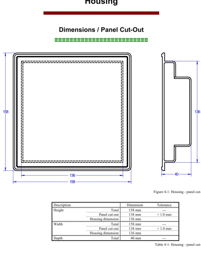
40 136 158 136 158Figure 4-1: Housing - panel cut-out Description Dimension Tolerance
Height Total 158 mm --- Panel cut-out 138 mm + 1.0 mm Housing dimension 136 mm Width Total 158 mm --- Panel cut-out 138 mm + 1.0 mm Housing dimension 136 mm Depth Total 40 mm ---
Installation
≡≡≡≡≡≡≡≡≡≡≡≡≡≡≡≡≡≡≡≡≡≡≡≡≡
For installation into a door panel, proceed as follows:1. Panel cut-out
Cut out the panel according to the dimensions in Figure 4-1.
2. Remove terminals
Loosen the wire connection terminal screws on the back of the unit and remove the wire connection terminal strips if required (1).
1
3. Loosen clamping screwsLoosen the four clamping screws (1) until they are almost flush with the clamp inserts and tilt the clamp inserts down by 45° (2) to remove them from the housing. Do not completely remove the screws from the clamp inserts.
1
2
4. Insert unit into cut-out
Insert the unit into the panel cut-out. Verify that the unit fits correctly in the cut-out. If the panel cut-out is not big enough, enlarge it accordingly. Ensure that the gasket is placed properly if used. Ensure that the paper strip is not pinched between gasket and panel to maintain isolation. 5. Attach clamp inserts
Re-install the clamp inserts by tilting the insert to a 45° angle (1). Insert the nose of the insert into the slot on the side of the housing. Raise the
clamp insert so that it is parallel to the control panel (2).
1
2
6. Tighten clamping screws
Tighten the clamping screws (1) until the control unit is secured to the control panel (2). Over tightening of these screws may result in the clamp inserts or the housing breaking. Do not exceed the recommended tighten-ing torque of 0.1 Nm.
1
2
7. Reattach terminals
Reattach the wire connection terminal strips (1) and secure them with the
side screws.
1
Note: If the gasket is damaged, it needs to be replaced. Use only the original gasket kit (P/N 3050-1057) for re-placement.
Chapter 5.
Wiring Diagrams
01 02 21 22 23 24 25 26 27 28 07 06 05 15 16 17 18 19 20 08 09 29 30 31 32 33 34 35 36 10 11 12 13 14 03 04 37 38 39 40The socket for the PC configuration is situated on the back of the item. This is were the DPC cable has to be plugged in.
Discrete input [DI 01] isolated Lock in manual mode Discrete input [DI 02] isolated Lock in auto mode Discrete input [DI 03] isolated Remote start Discrete input [DI 04] isolated Reply MCB / free configurable Discrete input [DI 05] isolated Reply GCB / free configurable Common (terminals 15 to 20) [DI 01] [DI 02] [DI 03] [DI 04] [DI 05]
Subject to technical modifications.
DT
SC-50
DTSC-50 Wiring Diagram | Rev. NEW
Mains voltage L3 Not connected Mains voltage L2 Mains voltage L1 Mains voltage N Not connected Not connected Not connected Relay [R 01] isolated MCB open Relay [R 02] isolated Engine start relay
Generator voltage L3 Not connected Generator voltage L2 Generator voltage L1 Generator voltage N Not connected Not connected Not connected Relay [R 03] Close GCB Relay [R 04] Free configurable Relay [R 05] Free configurable Relay [R 06] Free configurable Common (terminals 10 to 14) +
Chapter 6.
Connections
NOTE
The wire sizes in the following chapter are indicated in square millimeters. Please refer to Conversion Chart: Wire Size on page 90 to convert the sizes to AWG.
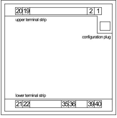
Terminal Arrangement
≡≡≡≡≡≡≡≡≡≡≡≡≡≡≡≡≡≡≡≡≡≡≡≡≡
2019
2
1
2122
3536
39
40
upper terminal strip
lower terminal strip
configuration plug
Power supply
≡≡≡≡≡≡≡≡≡≡≡≡≡≡≡≡≡≡≡≡≡≡≡≡≡
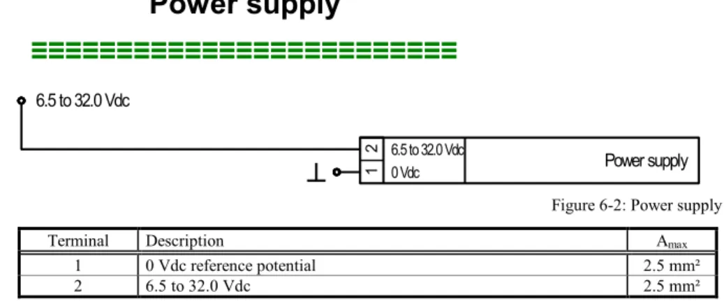
Power supply 2 1 0 Vdc 6.5 to 32.0 Vdc 6.5 to 32.0 VdcFigure 6-2: Power supply Terminal Description Amax
1 0 Vdc reference potential 2.5 mm² 2 6.5 to 32.0 Vdc 2.5 mm²
Table 6-1: Power supply - terminal assignment
For a proper operation of the device, a minimum initial voltage of 10.5 Vdc is necessary when switching on the DTSC. After this, a continuous operating voltage between 6.5 and 32 Vdc is possible to operate the DTSC-50 safely. The control unit is capable of handling voltage drops to 0 V for a maximum of 10 ms.
CAUTION
Ensure that the engine will be shut down by an external device in case the power supply of the DTSC-50 control unit fails. Failure to do so may result in damages to the equipment.
Voltage Measuring
≡≡≡≡≡≡≡≡≡≡≡≡≡≡≡≡≡≡≡≡≡≡≡≡≡
The DTSC-50 allows the use of different voltage measuring methods for generator and mains voltage depending on the model. These are described in the following text.
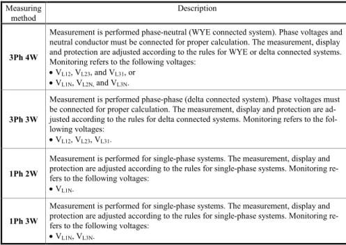
Measuring
method Description
3Ph 4W
Measurement is performed phase-neutral (WYE connected system). Phase voltages and neutral conductor must be connected for proper calculation. The measurement, display and protection are adjusted according to the rules for WYE or delta connected systems. Monitoring refers to the following voltages:
• VL12, VL23, and VL31, or • VL1N, VL2N, and VL3N.
3Ph 3W
Measurement is performed phase-phase (delta connected system). Phase voltages must be connected for proper calculation. The measurement, display and protection are ad-justed according to the rules for delta connected systems. Monitoring refers to the fol-lowing voltages:
• VL12, VL23, VL31.
1Ph 2W
Measurement is performed for single-phase systems. The measurement, display and protection are adjusted according to the rules for single-phase systems. Monitoring re-fers to the following voltages:
• VL1N.
1Ph 3W
Measurement is performed for single-phase systems. The measurement, display and protection are adjusted according to the rules for single-phase systems. Monitoring re-fers to the following voltages:
• VL1N, VL3N.
Table 6-2: Voltage measuring principles
The above described voltage measuring methods are shown with appropriate wiring examples for the different models for generator and mains voltage measuring in Figure 6-3 to Figure 6-11.
NOTE
LeoPC1 and a DPC cable (Revision B, P/N 5417-557) are required to configure the voltage measuring methods “1Ph2W”,“1Ph3W, “3Ph3W” and “3Ph4W”
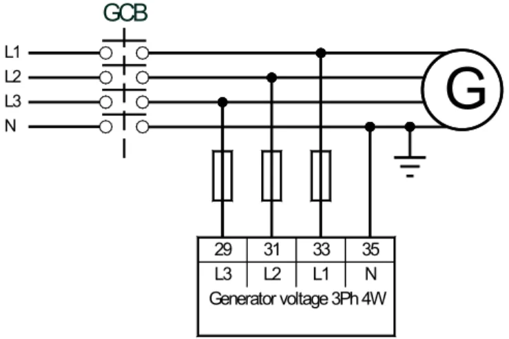
Voltage Measuring: Generator
Voltage Measuring: Generator 3Ph 4WL1 L2 L3 N
GCB
29 31 33 35 L3 L2 L1 N Generator voltage 3Ph 4WG
Figure 6-3: Voltage measuring - generator 3Ph 4W
Voltage Measuring: Generator 3Ph 3W
G
L1 L2 L3GCB
29 31 33 35 L3 L2 L1 N Generator voltage 3Ph 3WFigure 6-4: Voltage measuring - generator 3Ph 3W
Voltage Measuring: Generator 1Ph 3W
L1 L3 N
GCB
G
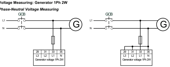
29 31 33 35 L3 L2 L1 N Generator voltage 1Ph 3WVoltage Measuring: Generator 1Ph 2W
Phase-Neutral Voltage Measuring
L1 N GCB 29 31 33 35 L3 L2 L1 N Generator voltage 1Ph 2W
G
L1 N GCB 29 31 33 35 L3 L2 L1 N Generator voltage 1Ph 2WG
Figure 6-6: Voltage measuring - generator 1Ph 2W, phase-neutral
Phase-Phase Voltage Measuring
It is also possible to perform a phase-phase voltage measuring. The units is intended for a phase-neutral measur-ing as described above, but may also be used for phase-phase voltage measurmeasur-ing. In this case, phase L2 must be connected to the N terminal of the DTSC-50 and the Generator rated voltage (Parameter 11) must be configured to the phase-phase voltage.
33 35 L1 N Generator voltage 1Ph 2W 31 29 L3 L2 L1 L2
GCB
G
Figure 6-7: Voltage measuring - generator 1Ph 2W, phase-phase Terminal Description Amax
29 Generator voltage - phase L3 480 Vac 2.5 mm² 31 Generator voltage - phase L2 480 Vac 2.5 mm² 33 Generator voltage - phase L1 480 Vac 2.5 mm² 35 Generator voltage - phase N 480 Vac 2.5 mm²
Table 6-3: Voltage measuring - terminal assignment - generator voltage
NOTE
If you select to perform a phase-phase voltage measuring, the display is still indicating a phase-neutral voltage since the voltage is measured between terminal 33 (L1) and 35 (N).
However, if the Generator rated voltage (Parameter 11) is configured correctly, the displayed value is the correct phase-phase voltage value.
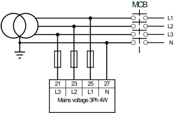
Voltage Measuring: Mains
Voltage Measuring: Mains 3Ph 4W21 23 25 27 L3 L2 L1 N Mains voltage 3Ph 4W
MCB
L1 L2 L3 NFigure 6-8: Voltage measuring - mains 3Ph 4W
Voltage Measuring: Mains 3Ph 3W
21 23 25 27 L3 L2 L1 N Mains voltage 3Ph 3W
MCB
L1 L2 L3Figure 6-9: Voltage measuring - mains 3Ph 3W
Voltage Measuring: Mains 1Ph 3W
21 23 25 27 L3 L2 L1 N Mains voltage 1Ph 3W
MCB
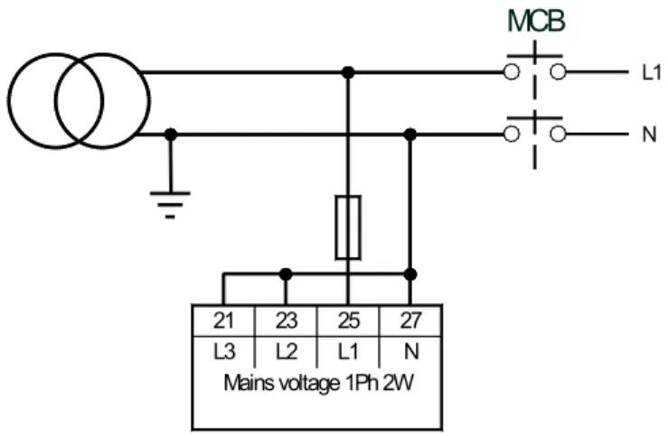
L1 L3 NVoltage Measuring: Mains 1Ph 2W L1 N 21 23 25 27 L3 L2 L1 N Mains voltage 1Ph 2W
MCB
Figure 6-11: Voltage measuring - mains 1Ph 2W Terminal Description Amax
21 Mains voltage - phase L3 480 Vac 2.5 mm² 23 Mains voltage - phase L2 480 Vac 2.5 mm² 25 Mains voltage - phase L1 480 Vac 2.5 mm² 27 Mains voltage - phase N 480 Vac 2.5 mm²
Discrete Inputs
≡≡≡≡≡≡≡≡≡≡≡≡≡≡≡≡≡≡≡≡≡≡≡≡≡
Discrete Inputs: Bipolar Signals
The discrete inputs are galvanically isolated allowing for a bipolar connection. The discrete inputs are able to handle positive or negative signals.
NOTE
All discrete inputs must use the same polarity, either positive or negative signals, due to the common ground.
Discrete Inputs: Positive Signal
16
17
Discrete input 1
15
6.5 to 32.0 Vdc
GND
Discrete input 2
Discrete input 3
18
Discrete input 4
19
Discrete input 5
20
6.5 to 32.0 Vdc
6.5 to 32.0 Vdc
6.5 to 32.0 Vdc
6.5 to 32.0 Vdc
Figure 6-12: Discrete inputs - alarm/control input - positive signal
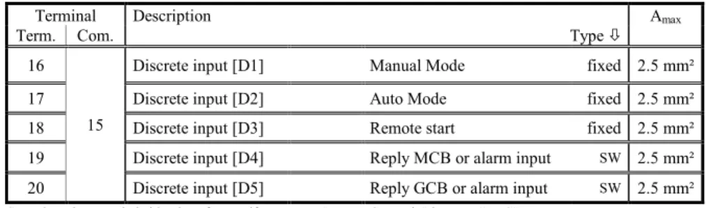
Terminal Description Amax
Term. Com. Type
16 15
Discrete input [D1] Manual Mode fixed 2.5 mm² 17 Discrete input [D2] Auto Mode fixed 2.5 mm² 18 Discrete input [D3] Remote start fixed 2.5 mm² 19 Discrete input [D4] Reply MCB or alarm input SW 2.5 mm² 20 Discrete input [D5] Reply GCB or alarm input SW 2.5 mm²
SW..alarm input switchable via software, if parameter "Ignore CB reply" is set to "YES"
Table 6-5: Discrete input - terminal assignment - alarm/control input - positive signal
NOTE
Discrete Inputs: Negative Signal 16 17
Discrete input 1
156.5 to 32.0 Vdc
GND
Discrete input 2
Discrete input 3
18Discrete input 4
19Discrete input 5
20GND
GND
GND
GND
Figure 6-13: Discrete inputs - alarm/control input - negative signal
Terminal Description Amax
Com. Term. Type
15
16 Discrete input [D1] Manual Mode fixed 2.5 mm² 17 Discrete input [D2] Auto Mode fixed 2.5 mm² 18 Discrete input [D3] Remote start fixed 2.5 mm² 19 Discrete input [D4] Reply MCB or alarm input SW 2.5 mm² 20 Discrete input [D5] - Reply GCB or alarm input SW 2.5 mm²
SW..alarm input switchable via software, if parameter "Ignore CB reply" is set to "YES"
Table 6-6: Discrete input - terminal assignment - alarm/control inputs - negative signal
Discrete Inputs: Operation Logic
Discrete inputs may be configured to be used for normally open (N.O) and normally closed (N.C.) contacts. The default condition for N.O. is that the voltage signal is low. If the N.O. contact closes, the signal becomes high and the DTSC-50 will detect an appropriate alarm or status.
The default condition for N.C. is that the voltage signal is high. If the N.C. contact opens, the signal becomes low and the DTSC-50 will detect an appropriate alarm or status.
The N.O. or N.C. contacts may be connected to the signal terminal or to the ground terminal of the discrete input. See previous chapter Discrete Inputs: Bipolar Signals on page 22 for details.
Discrete input (N.O.) Vdc (GND)
GND (Vdc)
Discrete input (N.C.) Vdc (GND)
GND (Vdc)
Figure 6-14: Discrete inputs - alarm/control inputs - operation logic
For the DTSC-50, the discrete inputs 1-3 are configured to a factory default and cannot be changed. The discrete inputs 4 and 5 are freely configurable depending on the parameter "Ignore CB reply". If this parameter is set to "YES", the discrete inputs are freely configurable, and the operation logic may be configured either to N.O. or N.C.
NOTE
Relay Outputs
≡≡≡≡≡≡≡≡≡≡≡≡≡≡≡≡≡≡≡≡≡≡≡≡≡
The DTSC-50 provides up to six (6) galvanically isolated relay outputs. Some relay outputs have fixed assign-ments and cannot be configured.
A
B Relay output
external device max. 250 Vac/dc
N/
Figure 6-15: Relay outputs
Terminal Description Amax
Term. Com.
A B Type
5/6 7 Relay output [R1] Command: open MCB fixed 2.5 mm² 8 9 Relay output [R2] Engine Start fixed 2.5 mm² 10 11 Relay output [R3] Close GCB 2.5 mm² 12 11 Relay output [R4] Free Configurable SW 2.5 mm² 13 11 Relay output [R5] Free Configurable SW 2.5 mm² 14 11 Relay output [R6] Free Configurable SW 2.5 mm² Table 6-7: Relay outputs - terminal assignment, part 1
The conditions, which can be assigned to the relay outputs R4, R5 and R6 are listed in Table 10-1: Relay outputs - list of configurable parameters on page 70 (refer to Relay Outputs on page 69).
Interfaces
≡≡≡≡≡≡≡≡≡≡≡≡≡≡≡≡≡≡≡≡≡≡≡≡≡
Service Port
The Woodward specific service port is a connector (RJ-45) to extend the interfaces of the controller.
Figure 6-16: Service port connector (RJ-45)
NOTE
The service port can be only used in combination with an optional Woodward direct configuration ca-ble (DPC).
Direct configuration cable (DPC)
The DPC cable is used to configure the device with the ToolKit configuration software and external exten-sions/applications.
There are two versions available:
• DPC-USB direct configuration cable • DPC-RS-232 direct configuration cable
DPC-USB direct configuration cable
Use the DPC-USB direct configuration cable if you want to connect the Woodward controller to an external de-vice (master) which is equipped with an USB port.
Order item number:
DPC-USB direct configuration cable – P/N 5417-1251
Figure 6-17: DPC-USB wiring - schematic
NOTE
1 Use the Ethernet CAT 5 cable which is supplied with the DPC-USB converter. The maximum cable
DPC-RS-232 direct configuration cable
Use the DPC-RS-232 direct configuration cable if you want to connect the Woodward controller to an external device (master) which is equipped with an RS-232 port.
Order item number:
DPC-RS-232 direct configuration cable – P/N 5417-557
Figure 6-18: DPC-RS-232 wiring - schematic
NOTE
1 Use the Ethernet CAT 5 cable which is supplied with the DPC-USB converter. The maximum cable
length must not exceed 0.5 m.
NOTE
For a continuous operation with the direct configuration cable DPC-RS-232 (e.g. remote control of con-troller), it is required to use at least revision F (P/N 5417-557 Rev. F) of the DPC-RS-232. When using a DPC-RS-232 of an earlier revision, problems may occur in continuous operation. The shield connector (6.3 mm tab connector) at the DPC-RS-232 of revision F (P/N 5417-557 Rev. F) and above must be con-nected to ground.
Chapter 7.
Operation and Navigation
Figure 7-1: Front panel and display
Figure 7-1 illustrates the front panel/display which includes push-buttons, LEDs and the alphanumerical 7 seg-ment LED display. A short description of the front panel is given below.
NOTE
This push-button is ALWAYS enabled and will stop the engine when pressed.
1 2 3
4 5 6
7 8
Push-buttons
The push buttons on the front panel are assigned to fixed functions of the unit.
9 10 11 12
13 14 15 16
17
LEDs
The LEDs indicate operating states of the unit and alarm messages. The right LED indicates that alarm messages are present in the unit.
18 7 segment LED display
This alphanumerical display is used to display all measured values, operating parameters, and alarm messages. A description of this display is detailed later in this manual.
Operation and Display
≡≡≡≡≡≡≡≡≡≡≡≡≡≡≡≡≡≡≡≡≡≡≡≡≡
Purpose of the Status LEDs
The DTSC-50 has several status LEDs to indicate the operating state. The LEDs indicate the following condi-tions:
LED 9 (on): Mains voltage present
LED 9 (flashing): Mains voltage and/or frequency are not within the (see page 47) LED 10: Mains circuit breaker (MCB) closed
LED 11: Generator circuit breaker (GCB) closed LED 12 (on): Generator in operation
LED 12 (flashing): Generator voltage and/or frequency are not within the (see page 47) LED 13 (on): Engine in operation
LED 13 (flashing): Engine in operation, but engine monitoring delay time (see page 55) not yet expired
LED 14: Alarm message present
LED 15: DTSC-50 in automatic operation mode
LED 16: DTSC-50 in manual operation mode
LED 17: DTSC-50 in stop operation mode
A function test of all LEDs and the seven-segment display may be conducted by pressing the 7 and 8 buttons simultaneously.
Operating the DTSC-50
• When the DTSC-50 control unit is powered up and the genset is not operating, LED 17 is illuminated and the MCB is closed
• The control unit may be started in automatic mode or have the operation mode changed from automatic to manual by pressing the Auto - Manual button 3. LED 15 (automatic) or LED 16 (manual) will indi-cate the current mode of operation by the corresponding LED being illuminated.
• The Breaker Control button 4 enables the operator to open or close the circuit breaker(s) depending on the current state of the breaker and the control unit being in manual operation mode. This button is disabled in automatic operation mode.
• The Start Engine button 5 will start the engine when the control unit is in manual operation mode. This button is disabled when the control unit is in automatic operation mode.
• The Stop button 6 is only enabled if Manual Mode or Automatic mode is NOT selected via the dis-crete inputs ( Terminals 16 and 17 ).If it is pressed while in automatic mode the engine will be shut down af-ter the configured cool down period has expired. Pressing this button twice will shutdown the genset immediately.
• Active alarm messages may be acknowledged with the Alarm button 2. Alarm conditions are indicated when LED 14 is illuminated.
• When the DTSC-50 is in normal operation, the operator may view the monitored parameters by using the Scroll button 1. The monitored values will be displayed on the 7-segment display 18 (a detailed de-scription of the displayed operating values may be found later in this manual).
Acknowledging Alarm Messages
LED 14 will flash when an alarm is active. The alarm message will be displayed in the 7-segment display 18. Pressing the alarm button 2 will acknowledge the alarm, reset the alarm relay (if relay is configured for alarm input), and the LED will change from flashing to continuously illuminated. If more than one fault condition is present, the operator may display these messages by pressing the Scroll button 1. The alarm may be
delet-ed by pressing and holding the Alarm button 2 a second time until the LED 14 is no longer illuminated. If the fault condition is still present, the LED 14 will remain illuminated and the unit stays in a locked mode accord-ing to the appropriate alarm condition.
Configuring the DTSC-50
To enter the configuration mode, press the Scroll 1 and Alarm 2 buttons simultaneously. Only the pa-rameters 00 - HMI Password, 01 - Time until horn reset and 72 - Display level are visible without entering a password. In order to display the other parameters, the correct password must be entered in the Parameter 00 - HMI Password. Pressing the Scroll button 1 will display the various parameters that may be changed. The
displayed values for the parameters may be changed by pressing the 7 and 8 buttons (a detailed descrip-tion of the parameters begins on page 52 of this manual). If the operator presses and holds these buttons, the rate of change for the value will increase. After the parameter has been adjusted to the desired value, enter it into the control unit by pressing the Scroll button 1 once. After a parameter has been changed and entered into the
control unit, the operator may advance to the next parameters by pressing the Scroll button 1 a second time. To exit the configuration mode, press the Scroll 1 and Alarm 2 buttons simultaneously again.
Display of the Operating Values
You may advance through the single value displays using the Scroll button 1.
The values are displayed numerically, while the engineering unit, source, and phase are coded in the seven-segment display 18 if applicable. See the example below:
Figure 7-2: 6 digit 7 segment LED display
• The first digit (counted from left) indicates what is being measured, (mains, ATS or generator). The top hor-izontal segment indicates mains, the middle horhor-izontal segment indicates engine, and the bottom horhor-izontal segment indicates generator.
• The second digit indicates the measured phase. The top segment indicates L1, the middle horizontal segment indicates L2, and the bottom horizontal segment indicates L3. If only one line is displayed for phase meas-urement, a phase to neutral measurement is displayed. If two lines are displayed, a phase to phase measure ment is shown.
• Digits 3-6 indicate what the measured value of the displayed parameter is.
• The indicators located at the top left of the first four digits of the display indicate the engineering unit of measure to be utilized. The indicators are assigned the following engineering units of measure.
o Digit 1: Volts [V]
o Digit 2: Frequency [Hz]
o Digit 3: Operating Hours [h]
o Digit 4: Number of Transfers to Gen.
With this information, the example in the figure above reads as follows: Voltage at generator between phase L2 and N is at 235.0 volts
Digit 1: Generator
Digit 2: Measurement between phase L2 and N Digits 3 to 6: Numerical value 235.0
Indicator at digit 4: Voltage [V]
Digits 5 and 6 of the display are used to display eight different alarm states. The upper and lower vertical seg-ments are used to indicate the various alarm states. Refer to on page 33 for the description of the alarm messages. For customization of your DTSC-50 front using the paper strips, refer to Front Customization on page 91.
Mains Generator
4 digit value display
No. of transfers to Gen.
Default Operating Value Display
The DTSC-50 detects and selects the default operating value display by evaluating the measured voltage and the circuit breaker position. This default operating value is always displayed first. The operator may advance through the following operating parameters using the Scroll button 1.
Voltage and CB position Voltage measuring Default operating value Generator voltage present
GCB is closed 1Ph 2W or 1Ph 3W Generator voltage V3Ph 3W or 3Ph 4W Generator voltage V1N12 Mains voltage present
MCB is closed 1Ph 2W or 1Ph 3W Mains voltage V3Ph 3W or 3Ph 4W Mains voltage V1N12
Table 7-1: Display - default operating value
If none of the conditions in Table 7-1 is fulfilled, the generator voltage V12 is displayed according to the order in Table 7-2.
NOTE
The operating value display depends on the set display level (refer to Parameter 72 on page 74).
Cycling Through the Displayed Operating Values
If the DTSC-50 is in normal operation, the default operating value is displayed. The operator may advance through the different operating parameters using the Scroll button 1. Following the default operating value, the parameters are displayed in the order shown below (some parameters will not display if the related function is disabled or not available on the control unit):
Parameter / display level Display Mains voltage V12 (phase-phase) DL 1 Mains voltage V23 (phase-phase) DL 2 Mains voltage V31 (phase-phase) DL 2 Mains voltage
Average of the phase-phase voltages (two of the three phase indicators are displayed alternately)
Mains voltage V1N (phase-neutral) DL 1 Mains voltage V2N (phase-neutral) DL 2 Mains voltage V3N (phase-neutral) DL 2 Mains voltage
Average of the phase voltages (one of the three phase indica-tors is displayed alternately) DL 2
Rated mains frequency DL 1 Generator voltage V12 (phase-phase) DL 1 Generator voltage V23 (phase-phase) DL 2 Generator voltage V31 (phase-phase) DL 2 Generator voltage
Average of the phase-phase voltages (two of the three phase-phase indicators are displayed alternately) DL 2
Generator voltage V1N (phase-neutral) DL 1 Generator voltage V2N (phase-neutral) DL 2 Generator voltage V3N (phase-neutral) DL 2 Generator voltage
Average of the phase voltages (one of the three phase indicators is displayed alternately) DL 1
Rated generator frequency DL 1
Operating hours counter (display is six-digit with one dec-imal)
DL 1
Hours to next maintenance (a negative value indicates excess hours, maintenance overdue) DL 2
Number of transfers to generator DL 2
Battery voltage DL 2
Table 7-2: Display of operating values
If the Scroll button 1 is pressed again, the display returns to the default operating value (refer to Default Op-erating Value Display on page 30). The display automatically returns after 180 seconds to the default opOp-erating value being displayed if a button isn’t pressed.
Alarm Messages
If the DTSC-50 detects a fault condition, LED 14 starts to flash. The alarm message is displayed in the seven-segment display 18 with a blinking "A" for alarm, an alarm number. The alarm may be acknowledged by pressing the Alarm button 2. The flashing LED and "A" will change to a continuously illuminated state and the relay will be reset. If more alarm conditions are present, the operator may advance through the different alarm messages using the Scroll button 1. By pressing the Alarm button 2 again, the alarm may be cleared unless the fault condition is still present.
Class Description Reaction of the system
B Alarm The operation is not interrupted but a centralized alarm is issued.
F Shutdown The GCB will be opened immediately and the engine will be stopped without cool down. Table 7-3: Alarm classes
The following table displays the possible alarm messages:
Alarm Alarm class Display
10 Generator overfrequency B: Alarm 11 Generator underfrequency B: Alarm 12 Generator over-voltage B: Alarm 13 Generator undervoltage B: Alarm 14 Mains rotation
field mismatch B: Alarm
30 Start fail B: Alarm
Alarm Alarm class Display 40 Maintenance hours B: Alarm
51 Generator breaker
close failure B: Alarm
52 Generator breaker
open failure B: Alarm
53 Mains breaker
close failure B: Alarm
54 Mains breaker
open failure B: Alarm
62 DI4: MCB reply or
free configurable Control input/ Selectable B or F 63 DI5: GCB reply or
free configurable Control input/ Selectable B or F
Table 7-4: Alarm messages
NOTE
Discrete Inputs 4 & 5: If the parameter "Ignore Breaker Replies" (only changeable via LeoPC1) is set to "YES", the discrete inputs for 4 and 5 are no longer control inputs. These discrete inputs may now be used as freely configurable alarm inputs. All alarm classes may be configured for these discrete in-puts.
Configuration Displays
The following parameters can be configured as described under Configuring the on page 29:
Parameter Range Display
00 DL 1 HMI Password 0000 to 9999 01 DL 1
Time until horn
reset 0 to 1000 s [1 s interval] 10 DL 3 Rated frequen-cy 50 Hz, 60 Hz 11 DL 3 Generator rated voltage 50 to 480 V [1 V interval] 12 DL 3 Mains rated voltage 50 to 480 V [1 V interval] 40 DL 3 Cooldown time 0 to 999 s [1 s interval] 50 DL 3 Generator overfrequency threshold 50.0 to 130.0 % [0.1 % interval] 51 DL 3 Generator overfrequency delay time 0.1 to 99.9 s [0.1 s interval] 52 DL 3 Generator underfrequency threshold 50.0 to 130.0 % [0.1 % interval]
53 DL 3 Generator underfrequency delay time 0.1 to 99.9 s [0.1 s interval] 54 DL 3 Generator overvoltage threshold 50.0 to 125.0 % [0.1 % interval] 55 DL 3 Generator overvoltage de-lay time 0.1 to 99.9 s [0.1 s interval] 56 DL 3 Generator undervoltage threshold 50.0 to 125.0 % [0.1 % interval] 57 DL 3 Generator undervoltage delay time 0.1 to 99.9 s [0.1 s interval] 70 DL 1 Maintenance hours 0 to 9999 h [1 h interval] 71 DL 1 Reset
mainte-nance hours 0 = no, 1 = yes
72 DL 1 Display level 1, 2, 3 80 DL 3 Mains settling time 0 to 9999 s [1 s interval] 81 DL 3 Mains over-voltage thresh-old 50.0 to 130.0 % [0.1 % interval]
82 DL 3 Mains undervoltage threshold 50.0 to 130.0 % [0.1 % interval] 83 DL 3 Mains voltage hysteresis 0.0 to 50.0 % [0.1 % interval] 84 DL 3 Mains overfrequency threshold 70.0 to 160.0 % [0.1 % interval] 85 DL 3 Mains underfrequency threshold 70.0 to 160.0 % [0.1 % interval] 86 DL 3 Mains frequen-cy hysteresis 0.0 to 50.0 % [0.1 % interval] 87 DL 3 Mains phase rotation moni-toring - self acknowledge 0 = Off 1 = On 88 DL 3 ModBus Slave ID 0 to 255
Table 7-5: Configuration displays
NOTE
The display automatically returns to the default operating value (refer to Default Operating Value Dis-play on page 30) if a button isn’t pressed within 180 seconds.
Display Hierarchy
The display system refreshes if a button isn't pressed within 180 seconds. The initial display depends on the pres-ence of alarm or error messages and the operating mode. The following display hierarchy applies:
Hierarchy level Display Comments
Alarm messages Alarm messages are displayed first if they are present (refer to Alarm Messages on page 33) 2 Operating values The operating values are displayed if no alarm or J1939 DM1/DM2 error messages are present in STOP operating mode or no alarm messages are present in MANUAL or AUTOMATIC operating
mode (refer to Display of the Operating Values on page 29)
Chapter 8.
Functional Description
Overview
≡≡≡≡≡≡≡≡≡≡≡≡≡≡≡≡≡≡≡≡≡≡≡≡≡
Operation Mode ( via Faceplate ) Manual ( via Faceplate ) AUTO ( via discrete in-Manual put )
Auto ( via discrete
in-put )
Operate the engine
• Start engine by:
the engine START - STOP push button YES --- YES ---
the discrete input DI3 (remote start) --- YES --- YES
emergency power (AMF) --- YES --- YES
• Stop engine by:
the STOP push button YES YES YES
---the discrete input DI3 (remote start) --- YES --- YES
emergency power (AMF) --- YES --- YES
an alarm --- --- ---
---• Operating mode selection:
the AUTO/MANUAL push button YES YES ---
---Operate GCB
• close GCB
the BREAKER CONTROL push button
(only if engine is running) YES --- YES --- emergency power (AMF) --- YES --- YES
• open GCB
the STOP push button YES YES YES
---the BREAKER CONTROL push button YES --- YES ---
emergency power (AMF) --- YES --- YES
an alarm (i.e. overvoltage) YES YES YES YES
Operate MCB
• open MCB
the BREAKER CONTROL push button YES --- YES ---
emergency power (AMF) --- YES --- YES
• close MCB
the STOP push button YES YES YES
---the BREAKER CONTROL push button
(only if mains are present) YES --- YES --- emergency power (AMF) --- YES --- YES
Table 8-1: Functional description - Overview
• Application Mode (page 38): depends on the application; defines the number/function of the breakers.
Operating Modes
≡≡≡≡≡≡≡≡≡≡≡≡≡≡≡≡≡≡≡≡≡≡≡≡≡
Operating Mode
STOP
Please consider the following :
If the operation modes “Auto” or “Manual” have been selected via discrete inputs, it is not possible to switch the device into operation mode “Stop”.
Selected Operation mode DTSC-50 will switch to operation mode STOP if “STOP” button is
pressed ?
AUTO ( via Faceplate ) Yes
Manual ( via Faceplate ) Yes
AUTO ( via discrete input ) No
Manual ( via discrete input ) No
In the STOP operating mode neither the engine or the power circuit breakers can be operated. The following occurs if operating mode STOP has been selected while…
…the engine is not running
1. The GCB will not close
2. “Engine Start” relay will not be set
3. The push buttons START and BREAKER CONTROL are disabled
4. The engine/generator monitoring remains de-activated (exception: all monitoring that is not delayed by the delayed engine speed monitoring)
5. The MCB will be closed if it is open
…the engine is running
1. The GCB will open if it is closed
2. The MCB will close if the GCB is open and mains are present 3. An engine cool down will be performed
4. The “Engine Start” relay is de-energized
5. Selected engine/generator monitoring functions (this includes under-voltage, -frequency) will be de-activated (exception: all monitoring that is not delayed by the delayed engine speed monitoring)
Operating Mode
MANUAL
NOTE
You find an overview about the buttons, LEDs and the seven-segment display under Operation and Navigation on page 27.
In the MANUAL operating mode (AUTO - MANUAL button 3) the engine and the power circuit breakers are operated via the BREAKER CONTROL button 4. The LED 16 in the upper right corner of the AUTO - MANUAL button 3 indicates the manual operating mode.
You can perform the following actions in the MANUAL operating mode depending on the application mode: The START button 5
Start the engine (if the engine is stopped, LED 13 is not illuminated)
The BREAKER CONTROL button 4
Open the GCB and close the MCB (if the control unit is in generator operation (LEDs 11 and 12 are illuminated) and mains are present, LED 9 is illuminated)
Open the MCB and close the GCB (if the control unit is in mains operation (LEDs 9 and 10 are il-luminated) and engine is running, LED 13 is illuminated)
Detailed operation in MANUAL mode (mains are not present)
Preconditions: • Generator is stopped – LED 12 is not illuminated • MCB is closed – LED 10 is illuminated
• Mains are present – LED 9 is illuminated • Unit is in manual mode – LED 16 is illuminated Engine start sequence:
Action START Press the START button 5
Operation Engine Start relay The engine start relay (relay 2) is energized to start the engine
– LED 12 illuminates and LED 13 starts flashing when generator volt-age and frequency has been detected
Delay Engine delay time The engine monitoring is delayed until time configured in the engine pa-rameters (page 55) expires – LED 13 changes to steady illumination af-ter the time expires
GCB close sequence:
Delay Generator settling
time The BREAKER CONTROL button will only be active after this timer has been expired. If this timer is not required by the user, it can be con-figured to “Zero” Seconds.
Action Breaker control Pressing the BREAKER CONTROL button 4
Operation Open MCB The MCB open relay (relay 1) energizes to open the MCB – LED 10 goes out
Delay Breaker delay The control unit waits for the breaker transfer time configured in the breaker parameters (page 56) to expire
Operation Close GCB The GCB close relay (relay 3) energizes to close the GCB – LED 11 il-luminates
MCB close sequence:
Action Breaker control Press the BREAKER CONTROL button 4
Operation Open GCB The GCB close relay (relay 3) de-energizes to open the GCB – LED 11 goes out
Delay Breaker delay The control unit waits for the breaker transfer time configured in the breaker parameters (page 56) to expire
Operation Close MCB The MCB open relay (relay 1) de-energizes to close the MCB – LED 10 illuminates
Stop sequence via STOP – BUTTON
( If MANUAL mode is select-ed via discrete input :
Please not that the following description is only valid if MANUAL mode has been selected via discrete input !
Action STOP Press the STOP - button 5
Operation Open GCB The GCB close relay (relay 3) de-energizes to open the GCB – LED 11 goes out
Operation Engine stop The engine stops – LEDs 12 and 13 go out
Action Breaker control Pressing the BREAKER CONTROL button 4
Operation Close MCB The MCB open relay (relay 1) de-energizes to close the MCB – LED 10 illuminates
Stop sequence via STOP one time:
( If MANUAL mode is select-ed via Faceplate )
Please not that the following description is only valid if MANUAL mode has been selected via the faceplate !
Action STOP Press the STOP button 6 once
Operation Open GCB The GCB close relay (relay 3) de-energizes to open the GCB – LED 11 goes out
Delay Breaker delay The control unit waits for the breaker transfer time configured in the breaker parameters (page 56) to expire
Operation Close MCB The MCB open relay (relay 1) de-energizes to close the MCB – LED 10 illuminates
Delay Cool down time The control unit waits for the cool down time configured in the engine parameters (page 55) to expire
Operation Engine stop The engine stops – LEDs 12 and 13 go out Stop sequence via STOP two
times:
( If MANUAL mode is se-lected via Faceplate )
Action STOP Press the STOP button 6 twice
Operation Open GCB The GCB close relay (relay 3) de-energizes to open the GCB – LED 11 goes out
Delay Breaker delay The control unit waits for the breaker transfer time configured in the breaker parameters (page 56) to expire
Operation Close MCB The MCB open relay (relay 1) de-energizes to close the MCB – LED 10 illuminates
Operation Engine stop The engine stops immediately without a cool down period – LEDs 12 and 13 go out
Detailed operation in MANUAL mode (mains are not present)
Preconditions: • Generator is stopped – LED 12 is not illuminated • MCB is closed – LED 10 is illuminated
• Mains are not present – LED 9 is not illuminated • Unit is in manual mode – LED 16 is illuminated
Engine start sequence:
Action START Press the START button 5
Operation Engine start relay The engine start relay (relay 2) is energized to engage the starter – LED 12 illuminates and LED 13 starts flashing when genera-tor speed has been detected
Delay Engine delay time The control unit waits for the engine monitoring delay time con-figured in the engine parameters (page 55) to expire – LED 13 changes to steady illumination after the time expires
GCB close sequence:
Delay Generator settling time The BREAKER CONTROL button will only be active after this timer has been expired. If this timer is not required by the user, it can be configured to “Zero” Seconds.
Action Breaker control Press the BREAKER CONTROL button 4
Operation Open MCB The MCB open relay (relay 1) energizes to open the MCB –
LED 10 goes out
Delay Breaker delay The control unit waits for the breaker transfer time configured in the breaker parameters (page 56) to expire
Operation Close GCB The GCB close relay (relay 2) energizes to close the GCB –
LED 11 illuminates GCB open sequence:
Action Breaker control Press the BREAKER CONTROL button 4
Operation Open GCB The GCB close relay (relay 3) de-energizes to open the GCB –
LED 11 goes out
Note The MCB close command will not be issued unless the mains re-turn
Stop sequence via STOP – BUTTON
( If MANUAL mode is selected via discrete input :
Please not that the following description is only valid if MANUAL mode has been selected via discrete input !
Action STOP Press the STOP button 5
Operation Open GCB The GCB close relay (relay 3) de-energizes to open the GCB –
LED 11 goes out
Operation Engine stop The engine stops – LEDs 12 and 13 go out Stop sequence via STOP one time:
( If MANUAL mode is selected via Faceplate )
Please not that the following description is only valid if MANUAL mode has been selected via the faceplate !
Action STOP Press the STOP button 6 once
Operation Open GCB The GCB close relay (relay 3) de-energizes to open the GCB –
LED 11 goes out
Delay Cool down time The control unit waits for the cool down time configured in the engine parameters (page 55) to expire
Operation Engine stop The engine stops – LEDs 12 and 13 go out Stop sequence via STOP two times:
( If MANUAL mode is selected via Faceplate )
Please not that the following description is only valid if MANUAL mode has been selected via the faceplate !
Action STOP Press the STOP button 6 twice
Operation Open GCB The GCB close relay (relay 3) de-energizes to open the GCB –
LED 11 goes out
Operating Mode AUTOMATIC
In the AUTOMATIC operating mode, all engine, GCB, and/or MCB functions are operated via the discrete inputs or automatically by the control unit (i.e. a mains failure). The function of the DTSC-50 depends on the configuration of the unit and how the external signals are used. LED 15, in the upper left corner of the AUTO - MANUAL button 3, indicates the automatic operating mode.
Detailed operation in automatic mode (mains are present)
Preconditions: • Generator is stopped – LED 12 is not illuminated • MCB is closed – LED 10 is illuminated
• Mains are present – LED 9 is illuminated • Unit is in automatic mode – LED 15 is illuminated Start sequence:
Action Remote start Discrete input DI3 (remote start) is activated (active HIGH signal) at terminal 18
Operation Engine start relay The engine start relay (relay 2) is energized to engage the starter – LED 12 illuminates and LED 13 starts flashing when generator speed has been detected
Delay Engine delay time The control unit waits for the engine monitoring delay time configured in the engine parameters (page 55) to expire – LED 13 changes to steady illumination after the time expires
Delay Generator settling
time The MCB will only be opened after this timer has been expired. If this timer is not required by the user, it can be configured to “Zero” Seconds. Operation Open MCB The MCB open relay (relay 1) energizes to open the MCB – LED 10
goes out
Delay Breaker delay The control unit waits for the breaker transfer time configured in the breaker parameters (page 56) to expire
Operation Close GCB The GCB close relay (relay 3) energizes to close the GCB – LED 11 il-luminates
Stop sequence:
Action Remote stop Discrete input DI3 (remote start) is deactivated (active LOW signal) at terminal 18
Operation Open GCB The GCB close relay (relay 3) de-energizes to open the GCB – LED 11 goes out
Delay Breaker delay The control unit waits for the breaker transfer time configured in the breaker parameters (page 56) to expire
Operation Close MCB The MCB open relay (relay 1) de-energizes to close the MCB – LED 10 illuminates
Delay Cool down time The control unit waits for the cool down time configured in the engine parameters (page 55) to expire
Detailed operation in automatic mode (mains are not present)
Preconditions: • Generator is stopped – LED 12 is not illuminated • MCB is closed – LED 10 is illuminated
• Mains are not present – LED 9 is not illuminated • Unit is in automatic mode – LED 15 is illuminated Start sequence:
Action Remote start Discrete input DI3 (remote start) is activated (active HIGH signal) at terminal 18
Operation Engine start relay The engine start relay (relay 2) is energized to engage the starter – LED 12 illuminates and LED 13 starts flashing when generator speed has been detected
Delay Engine delay time The control unit waits for the engine monitoring delay time configured in the engine parameters (page 55) to expire – LED 13 changes to steady illumination after the time expires
Delay Generator settling
time The MCB will only be opened after this timer has been expired. If this timer is not required by the user, it can be configured to “Zero” Seconds. Operation Open MCB The MCB open relay (relay 1) energizes to open the MCB – LED 10
goes out
Delay Breaker delay The control unit waits for the breaker transfer time configured in the breaker parameters (page 56) to expire
Operation Close GCB The GCB close relay (relay 3) energizes to close the GCB – LED 11 il-luminates
Stop sequence:
Action Remote stop Discrete input DI3 (remote start) is deactivated (active LOW signal) at terminal 18.
The engine will continue to run and the GCB remains closed since Mains is not present !
NOTE
If mains fails while the Remote start command ( via discrete input 3 ) is still active, the GCB will remain closed, and the engine start signal will still be kept set ! The remote start Signal is interpreted by the DTSC-50 as “Do not return to the mains source”, therefore no transfer actions will take place.