Washington University in St. Louis
Washington University Open Scholarship
Engineering and Applied Science Theses &Dissertations McKelvey School of Engineering
Spring 5-17-2017
Computations of Flow Fields of an Airfoil and a
Wing with Gurney Flap in Ground Effect
Xuan Zhang
Washington University in St. Louis
Follow this and additional works at:https://openscholarship.wustl.edu/eng_etds
Part of theEngineering Commons
This Thesis is brought to you for free and open access by the McKelvey School of Engineering at Washington University Open Scholarship. It has been accepted for inclusion in Engineering and Applied Science Theses & Dissertations by an authorized administrator of Washington University Open Scholarship. For more information, please [email protected].
Recommended Citation
Zhang, Xuan, "Computations of Flow Fields of an Airfoil and a Wing with Gurney Flap in Ground Effect" (2017).Engineering and Applied Science Theses & Dissertations. 258.
WASHINGTON UNIVERSITY IN ST. LOUIS School of Engineering and Applied Science
Department of Mechanical Engineering
Dissertation Examination Committee: Ramesh K. Agarwal, Chair
Swami Karunamoorthy Qiulin Qu
Computations of Flow Fields of an Airfoil and a Wing with Gurney Flap in Ground Effect by
Xuan Zhang
A thesis presented to
the School of Engineering and Applied Science of Washington University in
partial fulfillment of the requirements for the degree
of Master of Science
May 2017 St. Louis, Missouri
ii
Table of Contents
List of Figures ... iii
Acknowledgments... vi
ABSTRACT OF THE DISSERTATION ... vii
Chapter 1: Introduction ... 1
Chapter 2: Numerical Simulation of Flow Past NACA0012 Airfoil with Gurney Flap ... 3
2.1.1 Physical Model of Clean NACA0012 Airfoil ... 3
2.1.2 Physical Model of NACA0012 Airfoil with Gurney Flap ... 4
2.2.1 Numerical Method ... 8
2.2.2 Simulation Results ... 9
Chapter 3: Numerical Simulation of Flow Past NACA0012 Airfoil with Gurney Flap In Ground Effect ... 12
3.1.1 Model of NACA0012 Airfoil with Gurney Flap in Ground Effect ... 12
3.1.2 Mesh of NACA0012 Airfoil with Gurney Flap in Ground Effect ... 12
3.2.1 Simulation Settings and Boundary Conditions ... 14
3.2.2 Simulation Results ... 15
Chapter 4: Numerical Simulation of Flow Past FX-Cl3-152 Wing with Gurney Flap ... 23
4.1.1 Geometry of FX-Cl3-152 Wing with Slit Gurney Flap ... 23
4.1.2 Mesh Generation for FX-Cl3-152 Airfoil with Slit Gurney Flap ... 24
4.2.1 Simulation Settings and Boundary conditions ... 26
4.2.2 Simulation Results ... 26
Chapter 5: Numerical Simulation of Flow Past FX73-Cl3-152 Airfoil with Gurney Flap in Ground Effect... 31
5.2.1 Simulation settings and Boundary Condition... 33
5.2.2 Simulation Result of FX73-Cl3-152 Wing ... 33
5.2.3 Analysis of Result and Advantages for FX73-Cl3-152 with Gurney Flap with and without slits. 36 Chapter 6: Conclusion... 47
iii
List of Figures
Figure 1. Schematic of an airfoil with Gurney flap in low ride height above the ground. ... 2
Figure 2. Comparision of lift coefficient of NACA0012 Airfoil in unbounded flow and at low ride height h/c=0.2; U∞=40m/s and Re=2×10⁶ ... 4
Figure 3. NACA0012 Airfoil with Gurney Flap ... 5
Figure 4.Computational domain and mesh around of clean NACA0012 Airfoil ... 6
Figure 5. Computational domain of NACA0012 Airfoil With Gurney flap H=2%C ... 8
Figure 6. Comparison of computed and experimental lift and drag coefficient of clean NACA0012 Airfoil in unbounded flow ... 10
Figure 7. Comparison of computed and experimental lift and drag coefficient versus angle of attack of NACA0012 Airfoil with Gurney Flap H=2%C ... 11
Figure 8. Computational domain and mesh of NACA0012 airfoil with H=2%C, 𝛉 = 𝟗𝟎°Gurney Flap at h/c=0.2, ... 14
Figure 9. Comparison of lift and drag coefficient of clean NACA0012 airfoil and NACA0012 airfoil with H=2%C and θ = 90° Gurney flap in low ride height h/c = 0.2 ... 16
Figure 10. Comparison of lift and drag coefficients for flow past a NACA 0012 airfoil with H=2%C and θ = 90° Gurney flap at various ride height for various angle of attack. ... 17
Figure 11. Comparison of lift coefficient for flow past a NACA 0012 airfoil with h=2%C and θ = 90deg Gurney flap assuming that the lift coefficients due to ground effect and Gurney flap are coupled (∆𝑪𝒍)𝟐 and the lift coefficient due to the ground effect and Gurney flap are uncoupled (∆𝑪𝒍)𝟏 ... 18
Figure 12.Comparison of lift coefficient on the upper and lower surface of NACA 0012 airfoil with h=2%C and θ = 90° Gurney flap and clean NACA0012 airfoil. ... 19
Figure 13. Comparison of pressure coefficient for NACA0012 with H=2%C and θ = 90° Gurney flap at different ride height ... 20
Figure 14. Comparison of pressure coefficient for clean NACA0012 airfoil and NACA0012 airfoil with h=2%C and θ = 90° Gurney flap in unbounded flow and at ride height ride height h/c=0.2 ... 20
iv
Figure 15. Mirror image model of NACA0012 airfoil with H=2%C and θ = 90° Gurney flap (left) and clean NACA0012 airfoil (right) at low ride height h/c=0.2 ... 21 Figure 16. Pressure contours of NACA0012 airfoil with H=2%C and θ = 90° Gurney flap
(left) and clean NACA0012 (right) at low ride height h/c=0.2... 21 Figure 17. Stagnation streamlines of clean NACA0012 airfoil and NACA0012 with
H=2%C and θ = 90° Gurney flap in unbounded flow at low ride height h/c=0.2 ... 22 Figure 18.Physic model of FX73-Cl3-152 wing with H=1%C slit Gurney flap ... 23 Figure 19. Computational domain and mesh around FX73-Cl3-152 with H=1%C Gurney
flap ... 26 Figure 20.Comparison of computations and experimental data for clean FX73-Cl3-152 wing
in unbounded flow; M∞=0.117 and Re=2×10⁶ ... 28
Figure 21 Comparison of computed and experimental lift and drag coefficient for FX73 wing with H=1%C, 𝛉 = 𝟗𝟎° Gurney flap with slits in unbounded flow ... 29 Figure 22. Comparison of computed and experimental lift and drag coefficient for FX73
wing with H=1%C, 𝛉 = 𝟗𝟎° Gurney flap without slits in unbounded flow ... 30 Figure 23. Computational domain around the NACA0012 airfoil with Gurney flap. ... 32 Figure 24. Comparison of lift and drag coefficients of FX73-Cl3-152 wing with Gurney flap
of H = 1%C and θ=90° (with slits and without slits) in unbounded flow and in ground effect with h/c = 0.2; M∞=0.117 and Re=2×10⁶. ... 35
Figure 25. Polar diagram of FX73-Cl3-152 wing with H=1%C, θ=90° Gurney flap ... 36 Figure 26. Comparison of lift coefficient for FX73-Cl3-152 wing with Gurney flap without
and with slits; M∞=0.117 and Re=2×10⁶ ... 37
Figure 27. Comparison of drag coefficient for FX73-Cl3-152 wing with Gurney flap
without and with slits; M∞=0.117 and Re=2×10⁶ ... 37
Figure 28.Stagnation streamlines on clean FX73-Cl3-152 wing and FX73-Cl3-152 wing with Gurney flap of H=1%C, θ=90° in unbounded flow and at h/c = 0.2; M∞=0.117
and Re=2×10⁶. ... 39 Figure 29. Mirror image model of FX73-Cl3-152 wing with Gurney flap of H=1%C, θ=90°
at ride height h/c = 0.2; M∞=0.117 and Re=2×10⁶. ... 39
Figure 30. Pressure Contours around FX73-Cl3-152 wing section with Gurney flap of H=1%C, θ=90° at α=-5° (left) and α=5°(right); M∞=0.117 and Re=2×10⁶. ... 39
v
Figure 31. Pressure Coefficients at a FX73-Cl3-152 wing airfoil section with Gurney Flap without and with slit at h/c=0.2 and in unbounded flow; α=1°, M∞=0.117 and
Re=2×10⁶. ... 40 Figure 32. Various parts of FX73-Cl3-152 wing with Gurney flap without and with slit. .. 41 Figure 33. Pressure Coefficient at different sections of Gurney flap; α=1°, M∞=0.117 and
Re=2×10⁶. ... 41 Figure 34. Lift coefficient at different sections of the Gurney flap; ... 42 Figure 35. Drag coefficient for different parts of FX73-CL3-152 wing in unbounded flow;
α=1°, M∞=0.117 and Re=2×10⁶ ... 43
Figure 36. Drag coefficient for different parts of FX73-CL3-152 wing in unbounded flow; α=1°, M∞=0.117 and Re=2×10⁶ ... 43
Figure 37 Vortices at the trailing edge of FX73-Cl3-152 wing with H=1%C Gurney Flap in unbounded flow (Gurney flap with slit on left and Gurney flap without slit on right); α=1°, M∞=0.117 and Re=2×10⁶ ... 44
Figure 38. Pressure Contours on FX73-Cl3-152 wing with H=1%C Gurney flap in
unbounded flow (Gurney Flap with slit on left and Gurney flap without slit on right); α=1°, M∞=0.117 and Re=2×10⁶ ... 44
Figure 39 Vortices at trailing edge of FX73 wing with H=1%C Gurney flap with h/c = 0.2 ride height (Gurney flap with slit on left and Gurney flap without slit on right); α=1°, M∞=0.117 and Re=2×10⁶ ... 45
Figure 40. Pressure Contours on FX73 wing with H=1%C Gurney Flap at h/c = 0.2 ride height (Gurney flap with slit on left and Gurney flap without slip on right); α=1°, M∞=0.117 and Re=2×10⁶ ... 45
Figure 41. Drag polar of FX73-Cl3-152 wing with H=1%C Gurney flap without slit and with slit at ride height h/c=0.2; M∞=0.117 and Re=2×10⁶ ... 46
vi
Acknowledgments
I am deeply grateful to my supervisor, Dr. Ramesh K Agarwal for his enormous effort on my research and continuously providing me with many suggestions. Thanks to Dr. Qiulin Qu for his guidance and patience and suggestions in organizing the structure of the thesis. Thanks to everyone in CFD lab for providing a harmonious and friendly atmosphere.
Xuan Zhang
Washington University in St. Louis May 2017
vii
ABSTRACT OF THE DISSERTATION
Computations of Flow Fields of an Airfoil and a Wing with Gurney Flap in Ground effect by
Xuan Zhang
Master of Science in the department of Mechanical Engineering and Materials Science Washington University in St. Louis, 2017
Advisor: Professor Ramesh Agarwal
High lift devices used in transport aircraft are complex multi-element wings with slats and flaps which are difficult to design and they incur high manufacturing and maintenance costs. Taking all requirements into consideration, for light aircrafts using Gurney Flap may offer a low cost, low maintenance solution for improving the aerodynamic performance of aircraft during take-off and landing. Gurney Flap, first invented by Dan Gurney, is a small tab projecting from the trailing edge of airfoil. Gurney Flap can increase the lift coefficient and decrease the angle of attack for zero lift. However, at low angle of attack, Gurney flap also increases the drag coefficient. Overall, a net benefit in the lift-to-drag ratio can be provided by Gurney Flap since it increases the pressure on the lower surface of the airfoil upstream of the Gurney Flap. For generating the same lift force, less suction on the upper surface is needed with Gurney Flap. The effect of ground on a clean airfoil at moderate angles of attack is to increase the lift force and decrease the aerodynamic drag. The obstruction due to the ground increases the pressure on the lower surface of the wing and weakens the trailing vortices form the wing. This effect of ground on the airfoil aerodynamics has been demonstrated experimentally and computationally by many investigators. While the ground effect of a single airfoil and a multi-element airfoil has been
viii
studied for decades, few studies have been conducted on the ground effect due to a Gurney Flap. The goal of this thesis is to perform numerical simulations of flow over an airfoil/wing with a Gurney flap in ground effect and analyze its aerodynamic performance and flow physics.
1
Chapter 1: Introduction
Gurney Flaps are widely used in light aircrafts due to their advantage of ease in manufacturing and lower maintenance cost compared to the complex multi-element wings with slats and flaps used in modern transport aircraft. Figure 1 shows the schematic of an airfoil with Gurney flap close to the ground. The inset of Fig.1 shows a Gurney flap of length ‘H’ at the trailing edge at an angle θ from the chord. A Gurney flap can generally increase the lift-to-drag ratio of an airfoil since it increases the pressure on the lower surface of the airfoil upstream of Gurney flap [1]. However, at low angle of attack, the lift-to-drag ratio may become smaller since the Gurney flap may block the flow from moving downstream and therefore increase the drag. Modifications to the Gurney flap gave been suggested in the literature to provide better. The improvements to the performance of Gurney flaps using slit have been tested in the wind tunnel under unbounded flow condition. But the performance of a wing with Gurney flap in ground effect has not been analyzed to date in literature. The goal of this thesis is to perform numerical simulations of flow over a wing with Gurney flap with slit in ground effect and analyze its aerodynamic performance and flow physics.
2
Figure 1.Schematic of an airfoil with Gurney flap in low ride height above the ground.
1.1
Scope of Thesis
In this thesis, numerical simulations of the flow field of an airfoil and a wing are conducted in unbounded flow and in ground effect to analyze their aerodynamics and flow physics. For this purpose, first a NACA0012 airfoil with different shapes of Gurney flaps is considered. Computational results from ANSYS FLUENT are compared to the wind tunnel test results to verify the simulation model. Computations are then performed to include the ground effect. Next the ground effect aerodynamics of a wing with two different shapes of Gurney flaps is considered. Computational results from ANSYS FLUENT are compared to the wind tunnel test results to validate the simulation model. Computations are then performed to include the ground effect.
3
Chapter 2: Numerical Simulation of Flow
Past NACA0012 Airfoil with Gurney Flap
This Chapter describes the numerical simulations for flow past a NACA0012 airfoil in unbounded flow and in ground effect for various ride height condition. Physical and numerical models are built correspond to the experimental conditions for flow past a NACA0012 Airfoil with Gurney Flap in NF-3 wind tunnel test. For numerical simulation, the commercial CFD solver ANSYS FLUENT is employed to solve the Reynolds-Averaged Naver-Stokes(RANS) equations in corporation with the Spalart-Allmaras (SA) turbulence model.2.1 Physical Model of NACA0012 Airfoil with Gurney Flap
2.1.1 Physical Model of Clean NACA0012 Airfoil
The geometry of the clean NACA0012 Airfoil is imported from the 2D NACA0012 Airfoil Validation website at NASA Langley Research Center. The geometry has 257 grid points around the airfoil curve to provide an accurate description of the geometry. The chord length is 1m. The ground effect of a clean NACA0012 Airfoil is separated into two regions as shown in Fig.2: (1) when the angle of attack is smaller than 2.6°, it has a negative ground effect since the lift coefficient at low ride height is larger than in unbounded flow, and (2) when the angle of attack is larger than 2.6°, it has a positive ground effect since the lift coefficient at low ride height
4
becomes smaller than that in the unbounded flow. Based on the experimental data from NF-3 tunnel, the simulation focused in the angle of attack range of 2° to 8°. Fig.2 shows the comparison of lift coefficient of NACA0012 airfoil in unbounded flow and in ground effect for various angles of attack.
Figure 2. Comparision of lift coefficient of NACA0012 Airfoil in unbounded flow and at low ride height h/c=0.2; U∞=40m/s and Re=2×10⁶
2.1.2 Physical Model of NACA0012 Airfoil with Gurney Flap
According to NF-3 wind tunnel test, the NACA0012 with Gurney Flap model has a tab at the trailing edge at 90° with height of 2% of the chord length as shown in Fig.3. To ensure the shear stress, the width of the Gurney Flap is larger than 3mm. The free stream flow speed is 40𝑚/𝑠 (𝑀𝑎𝑐ℎ 𝑁𝑢𝑚𝑏𝑒𝑟 = 0.379) and the Reynolds number is 2×10⁶. The angle of attack varies from
-1 -0.8 -0.6 -0.4 -0.2 0 0.2 0.4 0.6 0.8 1 1.2 -4 -2 0 2 4 6 8 10
Lift
C
oe
ffi
cien
t
Angle of attack
Lift Coefficient of clean NACA0012
Airfoil at different ride height
h/c=inf h/c=0.2
5
2° to 8° and the ride height varies from 10% of the chord length (ℎ/𝑐 = 0.1) to an unbounded flow condition (ℎ/𝑐 = ∞).
Figure 3. NACA0012 Airfoil with Gurney Flap
2.2 Mesh Generation
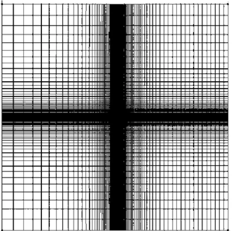
Geometry modeling and mesh generation is accomplished by ICEM software. Computational domain and mesh around a clean NACA airfoil is shown in Fig.4. Computational domain and mesh around NACA0012 with 2%C Gurney flap is drawn in Fig.5. In the CFD simulations, the airfoil is defined as no-slip wall. The inlet, outlet and top part of the rectangular domain are defined as pressure far field. The definition of bottom part depends on the ride height conditions. While in low ride height (ℎ/𝑐 ≤ 1.0), the bottom part is defined as moving wall and in an unbounded flow condition (ℎ/𝑐=∞), the bottom part is defined as pressure far field and Sutherland viscosity law is employed.
6
(a) Computational domain of clean NACA0012 airfoil
(b) Zoomed in view of clean NACA0012 Airfoil
7
(a) Computational domain around the NACA0012 airfoil with Gurney flap.
8
(c) Zoomed-in view of mesh near the Gurney flap
Figure 5. Computational domain of NACA0012 Airfoil With Gurney flap H=2%C
2.2 Flow Field Simulation of NACA0012 Airfoil without
and with Gurney Flap
2.2.1 Numerical Method
In the CFD simulation, Reynolds-Averaged Navier-Stokes (RANS) equations are solved in conjunction with SST k-ω turbulence model. The pressure based solver in FLUENT is employed. Both the convection and diffusion terms are discretized using a second-order accurate numerical scheme. Coupled algorithm is used to ensure pressure-velocity coupling. The air flow follows the ideal-gas law in density and Sutherland law for molecular viscosity is employed. The turbulence intensity in the far field is less than 0.045%.
9
2.2.2 Simulation Results
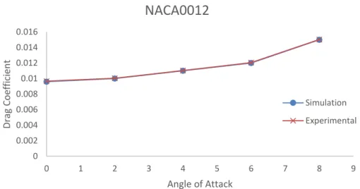
The simulation results primarily focus on the lift and drag coefficient comparing with the wind tunnel test data. Figure 6 shows that for clean NACA0012 airfoil, both the lift and drag coefficient are in excellent agreement with the experimental data. It should be noted that at higher angle of attack (>8deg), the flow becomes unsteady shedding large vortices at the trailing edge. Also the flow field in the simulations is assumed to be fully turbulent while in the experiment, the flow field is laminar near the leading edge which undergoes transition to become fully turbulent. Figure.7 shows the comparison of the computed and experimental lift and drag coefficient of NACA0012 airfoil with Gurney Flap with H=2%C and θ = 90°.
(a) Lift Coefficient versus angle of attack 0 0.1 0.2 0.3 0.4 0.5 0.6 0.7 0.8 0.9 1 0 1 2 3 4 5 6 7 8 9 Lif t Coe ff ici en t Angle of Attack
Lift Coefficient versus Angle of Attack for Clean
NACA0012
Simulation Experimental
10
(b) Drag coefficient versus angle of attack
Figure 6. Comparison of computed and experimental lift and drag coefficient of clean NACA0012 Airfoil in unbounded flow
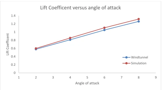
The computed results shown in Fig.7 are within 7% error of the experimental data [3]. In the NF-3 wind tunnel test, end plates are used to hold the airfoil in the tunnel and electronic balance are used to determine the lift and drag coefficient. The boundary layers in flow field at the end plate create three-dimensional features in flow field while the simulations are 2D.
0 0.002 0.004 0.006 0.008 0.01 0.012 0.014 0.016 0 1 2 3 4 5 6 7 8 9 Drag Coe ff ici en t Angle of Attack
Drag Coefficient versus Angle of Attack for Clean
NACA0012
Simulation Experimental
11
(a) Lift Coefficient versus angle of attack
(b) Drag Coefficient versus angle of attack
Figure 7. Comparison of computed and experimental lift and drag coefficient versus angle of attack of NACA0012 Airfoil with Gurney Flap H=2%C
0 0.2 0.4 0.6 0.8 1 1.2 1.4 1 2 3 4 5 6 7 8 9 Lif t Coe ff ice n t Angle of attack
Lift Coefficent versus angle of attack
Windtunnel Simulation 0 0.005 0.01 0.015 0.02 0.025 1 2 3 4 5 6 7 8 9 Drag C oe ff ci en t Angle of attack
Drag Coefficient versus angle of attack
Windtunnel Simulation
12
Chapter 3: Numerical Simulation of Flow
Past NACA0012 Airfoil with Gurney Flap In
Ground Effect
This chapter describes the numerical simulation of flow past NACA 0012 airfoil with Gurney flap in ground effect for various ride heights (h/c).
3.1 Model and Mesh of NACA0012 Airfoil with Gurney
Flap in Ground Effect.
3.1.1 Model of NACA0012 Airfoil with Gurney Flap in Ground Effect
The previous geometry NACA0012 Airfoil with Gurney flap described in section 2.3.2 is employed to make comparisons with of simulations in ground effect with those in unbounded flow. The Chord length of NACA 0012 Airfoil is set at 𝑐 = 1𝑚. For Gurney flap, thickness of the Gurney flap is 𝑙 = 1𝑚𝑚, θ = 90° and different height of Gurney flap are conducted.
3.1.2 Mesh of NACA0012 Airfoil with Gurney Flap in Ground Effect
Mesh of NACA0012 airfoil with Gurney flap in ground effect is shown in Fig.8. The total number elements in the mesh is about 170,000. The wall distance on the first mesh point is set at 10E-6 from the airfoil surface based on the Reynolds number 𝑅𝑒 = 2.1×10⁶ in NF-3 wind tunnel test, to ensure that y+<1, structured mesh is employed.
13
(a) Computational domain around the NACA0012 airfoil with Gurney flap in ground effect
14
(c) Zoomed-in mesh near the Gurney flap
Figure 8. Computational domain and mesh of NACA0012 airfoil with H=2%C, 𝛉 = 𝟗𝟎°Gurney Flap at h/c=0.2,
𝛂 = 𝟑°
3.2 Simulation of NACA0012 with Gurney Flap in Ground
Effect
3.2.1 Simulation Settings and Boundary Conditions
All simulation settings are kept the same as for the simulation in unbounded flow described in section 2.3.2. Boundary condition in the far field is defined as the pressure far field with turbulence intensity of less than 0.045%. Moving wall boundary condition is used for the ground with velocity same as the far field but in the opposite direction. Initial conditions for flow field employed the far field pressure and velocity conditions. To have better initial values, FMG solve is used after the standard initialization
15
3.2.2 Simulation Results
Figure.9 shows the validation of lift and drag coefficient with angle of attack at h/c=0.2 for a clean NACA0012 airfoil and NACA0012 airfoil with Gurney flap of H=2%C and θ = 90°. It can be seen that for airfoil with Gurney flap, the lift coefficient increases while the drag coefficient decreases relative to the clean airfoil without Gurney flap. Figure 10 shows the variation of lift and drag coefficient with ground height h/c for various angles of attack. It can be seen that both the lift and drag coefficients increases as the angle of attack increases.
(a) Lift Coefficient versus Angle of Attack 0 0.2 0.4 0.6 0.8 1 1.2 1.4 1.6 0 1 2 3 4 5 6 7 8 9 Lif t Coe ff ici en t Angle of Attack
Lift Coefficient Versus Angle of Attack in h/c=0.2
NACA0012 with Gurney Flap
16
(b) Drag Coefficient versus Angle of Attack
Figure 9. Comparison of lift and drag coefficient of clean NACA0012 airfoil and NACA0012 airfoil with H=2%C and θ = 90° Gurney flap in low ride height h/c = 0.2
(a) Lift coefficient versus angle of attack in low ride height and unbounded flow.. 0 0.002 0.004 0.006 0.008 0.01 0.012 0.014 0.016 0.018 0 2 4 6 8 10 Drag Coe ff ici en t Angle of Attack
Drag Coefficient Versus Angle of Attack in h/c=0.2
NACA0012 with Gurney Flap Clean NACA0012 0 0.2 0.4 0.6 0.8 1 1.2 1.4 1.6 1.8 0.1 0.2 0.5 1 inf Lif t Coe ff ici en t h/c
Lift Coefficient versus ride height
α=2° α=4° α=6° α=8°
17
(b) Drag coefficient versus angle of attack low ride height and low ride height.
Figure 10. Comparison of lift and drag coefficients for flow past a NACA 0012 airfoil with H=2%C and θ = 90° Gurney flap at various ride height for various angle of attack.
3.3 Analysis of NACA0012 with Gurney Flap in Ground
Effect
In order to analyze the aerodynamic effect from Gurney flap and ground effect separately, the case of clean NACA0012 airfoil in ground effect is also considered for comparison. Assuming that the increase in lift increase due to Gurney Flap and the ground effect are independent from each other; one can write.
(∆𝐶𝑙)1 = [𝐶𝑙(𝑐𝑙𝑒𝑎𝑛, ℎ/𝑐 = 0.2) − 𝐶𝑙(𝑐𝑙𝑒𝑎𝑛, ℎ/𝑐 = ∞)]
+ [𝐶𝑙(𝐻 = 2%𝑐 𝑔𝑢𝑟𝑛𝑒𝑦, ℎ/𝑐 = ∞) − 𝐶𝑙(𝑐𝑙𝑒𝑎𝑛, ℎ/𝑐 = ∞)]
The first term in the above equation is the enhancement in Cl due to ground effect and the second
term is the enhancement in Cl due to Gurney flap. The simulation result can be expected:
0.005 0.007 0.009 0.011 0.013 0.015 0.017 0.019 0.021 0.023 0.025 0.1 0.2 0.5 1 inf Drag Coe ff cie n t h/c
Drag Coeffcient versus ride height
α=2° α=4° α=6° α=8°
18
(∆𝐶𝑙)2 = 𝐶𝑙(𝐻 = 2%𝑐 𝑔𝑢𝑟𝑛𝑒𝑦, ℎ/𝑐 = 0.2) − 𝐶𝑙(𝑐𝑙𝑒𝑎𝑛, ℎ/𝑐 = ∞)
which implies the total lift coefficient increases
If the ground effect and the Gurney flap have an independent influence on the lift coefficient of the airfoil, (∆𝐶𝑙)1 = (∆𝐶𝑙)2 . However, according to the computational results in Fig.11,
(∆𝐶𝑙)1 > (∆𝐶𝑙)2. This figure implies that when an airfoil is in low ride height, the lift enhancement due to Gurney flap is weakened compared to that due to the ground effect.
Figure 11. Comparison of lift coefficient for flow past a NACA 0012 airfoil with h=2%C and θ = 90deg Gurney flap assuming that the lift coefficients due to ground effect and Gurney flap are coupled (∆𝑪𝒍)𝟐and the lift coefficient
due to the ground effect and Gurney flap are uncoupled (∆𝑪𝒍)𝟏
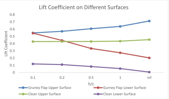
For a more specific analysis, lift coefficients of upper surface and lower surface are separately plotted in Fig.12. It can be seen that compared to the unbounded flow, the lower surface of the airfoil has more lift at lower ride heights. Compared with a clean NACA0012 airfoil, airfoil with Gurney flap increases the lift on both surfaces of the airfoil which makes the lift coefficient to
0 0.1 0.2 0.3 0.4 0.5 0.6 1 3 5 7 9 Lif t Coe ff cie n t Angle of Attack
Comparison of Lift Increment
Δ(Cl)1
19
increase in general. When the airfoil is at low ride height, NACA0012 airfoil with Gurney flap has a more obvious decrease in lift on its upper surface compared to the clean NACA0012 airfoil.
Figure 12.Comparison of lift coefficient on the upper and lower surface of NACA 0012 airfoil with h=2%C and θ = 90° Gurney flap and clean NACA0012 airfoil.
In Fig.13, the pressure coefficients show that on the airfoil even when the ride height decreases, the suction peak at the leading edge of the airfoil remains constant, and the pressure increases on the lower surface and the suction on the upper surface remains. This behavior of the pressure distribution can explain the lift coefficient on both the upper and the lower surface of the airfoil as discussed earlier. Figure.14 shows the pressure coefficients changed in the clean NACA0012 and NACA0012 airfoil with Gurney flap in the unbounded flow and at low ride height h/c=0.2. This figure shows that NACA0012 with Gurney flap has more suction on the upper surface when the airfoil is close to the ground.
0 0.1 0.2 0.3 0.4 0.5 0.6 0.7 0.8 0.1 0.2 0.5 1 inf Lif t Coe ff ici en t h/c
Lift Coefficient on Different Surfaces
Gruney Flap Upper Surface Gurney Flap Lower Surface Clean Upper Surface Clean Lower Surface
20
Figure 13. Comparison of pressure coefficient for NACA0012 with H=2%C and θ = 90° Gurney flap at different ride height
Figure 14. Comparison of pressure coefficient for clean NACA0012 airfoil and NACA0012 airfoil with h=2%C and θ = 90° Gurney flap in unbounded flow and at ride height ride height h/c=0.2
Figure15 shows a mirror image model of NACA0012 airfoil at angle of attack= 4° with h/c=0.1 with and without Gurney flap ride height. It can be seen from the figure that NACA0012 airfoil
-2.7 -2.2 -1.7 -1.2 -0.7 -0.2 0.3 0.8 1.3 0 0.2 0.4 0.6 0.8 1 Pres su re Coe ff ice n t x
Pressure Coefficent On NACA0012 Airfoil with Gurney Flap at
Different Ride Height
h/c=0.1 h/c=0.2 h/c=0.5 h/c=1.0 -2.7 -2.2 -1.7 -1.2 -0.7 -0.2 0.3 0.8 1.3 0 0.2 0.4 0.6 0.8 1 Pres su re Coe ff ice n t x/c
Pressure Coefficient On NACA0012 Airfoil with & without Gurney
Flap in Unbounded Flow and at h/c=0.2
Clean h/c=infclean h/c=0.2 H=2%c Gurney Flap h/c=inf H=2%c Gurney Flap h/c=0.2
21
with Gurney flap at the trailing edge has smaller area at nozzle exit since the Gurney flap decreases the ground clearance at the trailing edge. The smaller area at nozzle exit leads to larger pressure on the lower surface. This result can be validated from the pressure contour shown in Figure16.
Figure 15. Mirror image model of NACA0012 airfoil with H=2%C and θ = 90° Gurney flap (left) and clean NACA0012 airfoil (right) at low ride height h/c=0.2
Figure 16. Pressure contours of NACA0012 airfoil with H=2%C and θ = 90° Gurney flap (left) and clean NACA0012 (right) at low ride height h/c=0.2
22
Figure 17. Stagnation streamlines of clean NACA0012 airfoil and NACA0012 with H=2%C and θ = 90° Gurney flap in unbounded flow at low ride height h/c=0.2
In Fig.17 for NACA0012 airfoil, one streamline begins from upstream and terminates at stagnation point and another begins from the trailing edge and goes to downstream. The comparison of stagnation streamlines between clean NACA0012 airfoil and NACA0012 airfoil with Gurney flap shows that the Gurney flap increase the effective camber of NACA0012 airfoil. More effective camber generates more suction on the upper surface and increases the lift coefficient. However, in low ride height, the stagnation streamline is flattened by the obstruction of ground and the effective camber of the airfoil decreases, leading to less lift coefficient on the upper surface.
23
Chapter 4: Numerical Simulation of Flow
Past FX-Cl3-152 Wing with Gurney Flap
In the previous chapter3, the 2D results showed that while a Gurney flap can increase the lift coefficient of the airfoil, it will increases 2D drag coefficient. In order to reduce the drag, also several modifications to the Gurney flap have been suggested in the literature, one is create slits at the trailing edge. With slits at the trailing edge, flow instability is suppressed at high angle of attack reduce the drag.4.1 Physical Model of FX73-Cl3-152 Airfoil with Gurney
Flap
4.1.1 Geometry of FX-Cl3-152 Wing with Slit Gurney Flap
The geometry of clean FX-Cl3-152 rectangular wing (airfoil section) is taken from UIUC Airfoil Database with 98 points around the airfoil to define its geometry. The wing has 1.55m span and 0.5m chord length with 𝐻 = 1%𝑐 Gurney flap height at θ = 90°. The slit has a 0.2mm gap with a 2mm interval on the Gurney flap as drawn in Figure.18.
24
4.1.2 Mesh Generation for FX-Cl3-152 Airfoil with Slit Gurney Flap
Figure.19 shows the computational domain and mesh around the FX73-Cl3-152 airfoil/wing with slit Gurney flap and without Gurney flap. The total elements of the mesh is about 1,400,000. The wall distance is set at 10E-5 from the airfoil surface based on the Reynolds number is 𝑅𝑒 = 2.1×10⁶ in wind tunnel. To ensure y+<1 3D structured is generated. The span of the airfoil in
mesh is 2.2mm since the airfoil is translational periodic. A periodic mesh of left and right side is made. The quality of the mesh has been controlled higher than 0.6 and the ratio between neighboring elements are less than 1.2. The parts in project are divided into fluent part, pressure far field part, airfoil part, periodic1 part and periodic2 part.
25
(a) Computational domain around the FX73-Cl3-152 wing with Gurney flap.
(b) Mesh around the FX73-Cl3-152 wing with slit Gurney flap of H =1%C and 𝛉 = 𝟗𝟎° at the trailing edge.
d=10c d=25c
d=
10c
d=
26
(c) Mesh around the FX73-Cl3-152 wing with no slits Gurney flap of H =1%C and 𝛉 = 𝟗𝟎° at the trailing edge. Figure 19. Computational domain and mesh around FX73-Cl3-152 with H=1%C Gurney flap
4.2 Simulation of FX-Cl3-152 Wing with Gurney Flap
4.2.1 Simulation Settings and Boundary conditions
All simulation settings for the numerical algorithm are kept the same as described in section 2.3.2 for 2D simulations of an airfoil in unbounded flow. Boundary condition in the far field is defined as the pressure far field with turbulence intensity of less than 0.045%. Initial conditions for the flow field employ the far field pressure and velocity conditions.
4.2.2 Simulation Results
Figure.20 shows the variation of computed lift and drag coefficients with angle of attack for clean FX73-Cl3-152 wing and their comparison with the experimental data. Excellent agreement is obtained; the difference between the simulations and experimental data is less than 0.15%. Figure.21 and 22 show the variation of the computed lift and drag coefficients with angle of attack for FX73-Cl3-152 wing with Gurney flap of height H=1.0%C and θ=90° at the trailing edge of the wing with and without slits respectively and their comparison with the experimental
27
data. Satisfactory agreement is obtained. All results shown in Fig.21 and Fig.22 are within 5% error compared to the experimental data [6]. In the wind tunnel test, end plates are used to hold the wing and electronic balance is used to de0termine the lift and drag coefficients. The boundary layers at the end plates influence the wind tunnel results; however, the simulations do not take the end plates into consideration. It should be noted that at higher angles of attack (> 11deg.), the flow becomes unsteady shedding large vortices at the trailing edge. Also, the flow in the computations is assumed to be fully turbulent while in the experiment the flow-field is not fully turbulent.
(a) Lift coefficient versus angle of attack 0 0.2 0.4 0.6 0.8 1 1.2 1.4 1.6 1.8 -6 -4 -2 0 2 4 6 Lif t Coe ff ici en t Angle of Attack
Lift Coefficient vs. Angle of Attack for clean FX73-Cl3-152 Wing
CFD Result Wind Tunnel Result
28
(b) Drag coefficient versus angle of attack
Figure 20.Comparison of computations and experimental data for clean FX73-Cl3-152 wing in unbounded flow; M∞=0.117 and Re=2×10⁶
(a) Lift Coefficient versus angle of attack 0 0.005 0.01 0.015 0.02 0.025 -6 -4 -2 0 2 4 6 Lif t Coe ff ici en t Angle of Attack
Drag Coefficient versus Angle of Attack for clean
FX73-Cl3-152 Airfoil
CFD Result Wind Tunnel Result
0 0.2 0.4 0.6 0.8 1 1.2 1.4 1.6 1.8 2 -6 -4 -2 0 2 4 6 LIft Coe ff cie n t Angle of Attack
Lift Coefficient versus angle of attack for FX73-Cl3-152
Wing with Gurney flap with slits
Simulation windtunnel
29
(b) Drag Coefficient versus angle of attack
Figure 21 Comparison of computed and experimental lift and drag coefficient for FX73 wing with H=1%C, 𝛉 = 𝟗𝟎° Gurney flap with slits in unbounded flow
(a) Lift Coefficient versus angle of attack 0 0.005 0.01 0.015 0.02 0.025 0.03 0.035 -6 -4 -2 0 2 4 6 Drag C oe ff ic ie n t Angle of Attack
Drag Coefficient versus angle of attack for FX73-Cl3-152
Wing with Gurney flap with slits
Simulation windtunnel 0 0.2 0.4 0.6 0.8 1 1.2 1.4 1.6 1.8 2 -6 -4 -2 0 2 4 6 Lif t Coe ff ici en t Angle of Attack
Lift Coefficient versus angle of attack for FX73-Cl3-152
wing with Gurney flap without Slits
Simulation Windtunnel
30
(b) Drag Coefficient versus angle of attack
Figure 22. Comparison of computed and experimental lift and drag coefficient for FX73 wing with H=1%C, 𝛉 = 𝟗𝟎° Gurney flap without slits in unbounded flow
0 0.005 0.01 0.015 0.02 0.025 0.03 0.035 -6 -4 -2 0 2 4 6 Drag Coe ff ici en t Angle of Attack
Drag Coefficient versus Angle of Attack for FX73-Cl3-152
Wing with Gurney flap without Slits
31
Chapter 5: Numerical Simulation of Flow
Past FX73-Cl3-152 Airfoil with Gurney Flap
in Ground Effect
In chapter4, the results showed that while Gurney flap can increase the lift coefficient of the wing, it also increases the drag coefficient. In order to further increase the lift coefficient and reduce the drag coefficient. Gurney flap with slits should be employed. It should be noted however that there is only a small difference in lift and drag coefficient by using the Gurney flap with and without slits.
5.1 Model and Mesh of FX-Cl3-152 Wing with Gurney Flap
in Ground Effect
In chapter 4, the physical model of the wing with Gurney flap wit slits and without slits was described. Same model of the FX73-Cl3-152 Wing with Gurney flap with and without slits in ground effect is employed in this chapter. Figure.23 shows the computational domain for the wing in ground effect. The mesh is similar to that described in section 4.1.2. Boundary conditions are the same as those described in section 4.2.1 except that a moving wall boundary condition is employed on the ground.
32
Figure 23. Computational domain around the NACA0012 airfoil with Gurney flap.
d=10c
d=
10c
33
5.2 Simulation of FX73-Cl3-152 Airfoil with Gurney Flap
in Ground Effect
5.2.1 Simulation settings and Boundary Condition
All simulation settings for the numerical algorithm are kept the same as described in section 3.2.1 for 2D simulations of airfoil in ground effect. All boundary conditions are also the same as described in section 3.2.1.
5.2.2 Simulation Result of FX73-Cl3-152 Wing
The results show that in ground effect, the wing with slit Gurney flap generate smaller lift and drag compared to that in unbounded flow (Fig.24), leading to a larger lift-to-drag ratio at low angles of attack (from 𝛼 = −5° 𝑡𝑜 𝛼 = 5°). At larger angle of attack, more drag force is reduced in ground effect. This phenomenon occurs in case of Gurney flap with slits and Gurney flap without slits.
(a) Comparison of lift coefficients in unbounded flow and ground effect for FX73-Cl3-152 wing with H=1%C, θ = 90° Gurney Flap with slits
0 0.2 0.4 0.6 0.8 1 1.2 1.4 1.6 1.8 -6 -4 -2 0 2 4 6 LIft Coe ff cie n t Angle of Attack
Lift Coefficient vs. Angle of Attack
34
(b) Comparison of drag coefficient in unbounded flow and ground effect FX73-Cl3-152 wing with H=1%C , θ = 90° Gurney flap with slits
(c) Comparison of lift coefficients in unbounded flow and ground effect for FX73-Cl3-152 wing with H=1%C, θ = 90° Gurney Flap without slits
0 0.005 0.01 0.015 0.02 0.025 0.03 -6 -4 -2 0 2 4 6 Drag Coe ff ici en t Angle of Attack
Drag Coefficient vs. Angle of Attack
FX73 GF=1% h/c=inf FX73 GF=1% h/c=0.2 0 0.2 0.4 0.6 0.8 1 1.2 1.4 1.6 1.8 -6 -4 -2 0 2 4 6 Lif t Coe ff ici en t Angle of Attack
Lift Coefficient vs. Angle of Attack
35
(d) Comparison of drag coefficient in unbounded flow and ground effect FX73-Cl3-152 wing with H=1%C , θ = 90° Gurney flap without slits
Figure 24. Comparison of lift and drag coefficients of FX73-Cl3-152 wing with Gurney flap of H = 1%C and θ=90° (with slits and without slits) in unbounded flow and in ground effect with h/c = 0.2; M∞=0.117 and
Re=2×10⁶.
Figure 25 shows that in ground effect, both the Gurney flap with and without slits can provide higher lift-to-drag ratio compared to the lift-to-drag ratio in the unbounded flow. Furthermore, in ground effect, the Gurney flap with slits has a slightly larger lift-to-drag ratio compared to the Gurney flap without slits.
0 0.005 0.01 0.015 0.02 0.025 0.03 -6 -4 -2 0 2 4 6 Drag Coe ff ici en t Angle of Attack
Drag Coefficient vs. Angle of Attack
36
Figure 25. Polar diagram of FX73-Cl3-152 wing with H=1%C, θ=90° Gurney flap
5.2.3 Analysis of Result and Advantages for FX73-Cl3-152 with Gurney Flap
with and without slits.
Figure 26 shows the variation in lift coefficient with angle of attack for FX73-Cl3-152 wing with Gurney flap without slits and with slits. It can be seen that the lift coefficient is not affected by the type of Gurney flap (without slits or with slits); however, the drag coefficient is affected by
-0.01 -0.005 0 0.005 0.01 0.015 0.02 0.025 0.03 0 0.25 0.5 0.75 1 1.25 1.5 1.75 2 -6 -5 -4 -3 -2 -1 0 1 2 3 4 5 6 Drag Coefficent Lif t Coe ff cie n t Angle of Attack
Polar Diagram of FX73-Cl3-152 With Gurney Flap
Unbounded Without Slits Cl vs α
Ground effect Without Slits Cl vs α
Unbounded with Slits Cl vs α
Ground effect With Slits Cl vs α
Unbounded Without Slits Cl vs Cd Ground effect Without Slits Cl vs Cd Unbounded With Slits Cl vs Cd
Ground Effect With Slits Cl vs Cd
37
the type of Gurney flap, the flap without slit has higher drag compared to that with slits as shown in Figure. 27.
Figure 26. Comparison of lift coefficient for FX73-Cl3-152 wing with Gurney flap without and with slits; M∞=0.117 and Re=2×10⁶
Figure 27. Comparison of drag coefficient for FX73-Cl3-152 wing with Gurney flap without and with slits; M∞=0.117 and Re=2×10⁶ 0.5 0.7 0.9 1.1 1.3 1.5 1.7 1.9 -6 -4 -2 0 2 4 6 Lif t Coe ff cie n t Angle of Attack
Lift Coeffcient vs. Angle of Attack
Gurney Flap with Slits Gurney Flap without Slits
0.015 0.017 0.019 0.021 0.023 0.025 0.027 0.029 -6 -4 -2 0 2 4 6 Drag Coe ff cie n t Angle of Attack
Drag Coeffcient vs. Angle of Attack
38
Figure 28 shows a pair of streamlines on the upper surface of the Gurney flap, one streamline begins from upstream and terminates at the stagnation point and another one begins at the trailing edge and goes towards the downstream boundary. Figure 28 shows that the Gurney flap can increase the effective camber of the clean wing FX73-Cl3-152. However, the blockage effect of the ground can reduce the effective camber of the wing, thus the increase in effective camber due to Gurney flap gets weakened due to the presence of the ground. On the other hand, the lower surface of the wing and the ground form a nozzle as shown in Fig. 29. The blockage of the ground is increased by the Gurney flap which creates more pressure at trailing edge of the wing and thus more lift as shown in pressure contours Fig.30. In general, FX73-Cl3-152 wing with H=1%C, θ = 90° Gurney flap has a negative ground effect when angle of attack is smaller than
5°. Figure 31 shows the pressure coefficients of FX73-Cl3-152 wing with H=1%C, θ = 90°
Gurney flap without and with slits in unbounded flow and in ground effect. This figure shows that the pressure decreases on the upper surface and increases on the lower surface of the wing in unbounded flow compared to that in ground effect at h/c=0.2. However FX73-Cl3-152 wing with Gurney flap with slit and without slit has similar pressure distributions at the same ride height.
39
Figure 28.Stagnation streamlines on clean FX73-Cl3-152 wing and FX73-Cl3-152 wing with Gurney flap of H=1%C, θ=90° in unbounded flow and at h/c = 0.2; M∞=0.117 and Re=2×10⁶.
Figure 29. Mirror image model of FX73-Cl3-152 wing with Gurney flap of H=1%C, θ=90° at ride height h/c = 0.2; M∞=0.117 and Re=2×10⁶.
Figure 30. Pressure Contours around FX73-Cl3-152 wing section with Gurney flap of H=1%C, θ=90° at α=-5° (left) and α=5°(right); M∞=0.117 and Re=2×10⁶.
40
Figure 31. Pressure Coefficients at a FX73-Cl3-152 wing airfoil section with Gurney Flap without and with slit at h/c=0.2 and in unbounded flow; α=1°, M∞=0.117 and Re=2×10⁶.
For further analysis, the FX73-Cl3-152 wing with H=1%C Gurney flap with slit is divided into three sections and two parts: in chordwise direction the wing is divided into the wing part (97% of chord) and the flap part (3% of chord), in the spanwise direction the wing is equally divided into slit section (wing without Gurney flap), boundary section (half of wing with Gurney flap) and Gurney flap section (wing with Gurney flap) as shown in figure 32. Two spanwise sections of same width are used for comparison.
-2.5 -2 -1.5 -1 -0.5 0 0.5 1 1.5 -0.05 0.15 0.35 0.55 0.75 0.95 Pres su re Coe ff ice n t x/c
Pressure Coeffcients at a FX73-Cl3-152 Wing Airfoil Section with H=1%C Gurney Flap
With Slits h/c=inf With Slits h/c=0.2 Without Slits h/c=inf Without Slits h/c=0.2
41
Figure 32. Various parts of FX73-Cl3-152 wing with Gurney flap without and with slit.
Figure. 33 shows the pressure coefficient distribution on the flap part. At trailing edge, the slit section has less suction on the upper surface and pressure on the lower surface, which results in less lift in the slit section and thus some loss of lift for FX-Cl3-152 wing with H=1%C Gurney flap with slit compared to that for the wing with Gurney flap without slit as shown in Figure. 34.
Figure 33. Pressure Coefficient at different sections of Gurney flap; α=1°, M∞=0.117 and Re=2×10⁶.
-0.4 -0.2 0 0.2 0.4 0.6 0.8 -1.5E-04-1.0E-04-5.0E-050.0E+005.0E-051.0E-04 1.5E-04 Pres su re Coe ff ici en t posistion Pressure Coefficient on Gurney flap
at Slit at Boundary At Gurney Flap
-0.4 -0.2 0 0.2 0.4 0.6 0.8
-1.5E-04-1.0E-04-5.0E-050.0E+005.0E-05 1.0E-04 1.5E-04
Pres su re Coe ff ici en t posistion Pressure Coefficient on Gurney flap
42
Figure 34. Lift coefficient at different sections of the Gurney flap; α=1°, M∞=0.117 and Re=2×10⁶.
Figure 35 and Figure 36 show the drag coefficient in different parts of the wing and the flap in unbounded flow and in ground effect at h/c = 0.2 respectively. For all parts, the viscous drag coefficient is constant and the pressure drag coefficient decreases when FX73-Cl3-152 wing is in low ride height. This explains the decrease in total lift coefficient when the wing is in low ride height. In both unbounded flow and in ground effect, the wing part contributes more to the drag coefficient. In all sections, the slit section has the smallest drag coefficient in both the unbounded flow and in ground effect. This explains the smaller drag coefficient of FX73-Cl3-152 wing Gurney flap with slit.
5.97E-02 6.28E-02 6.28E-02 5.80E-02 5.85E-02 5.90E-02 5.95E-02 6.00E-02 6.05E-02 6.10E-02 6.15E-02 6.20E-02 6.25E-02 6.30E-02 6.35E-02 Lif t Coe ff ice n t
Lift Coefficient at different sections of Gurney flap
43
Figure 35. Drag coefficient for different parts of FX73-CL3-152 wing in unbounded flow; α=1°, M∞=0.117 and
Re=2×10⁶
Figure 36. Drag coefficient for different parts of FX73-CL3-152 wing in unbounded flow; α=1°, M∞=0.117 and
Re=2×10⁶
In unbounded flow, FX73-Cl3-152 wing with Gurney flap with slit enables the flow to go through slits instead of being blocked by the Gurney flap. A pair of vortices is formed as shown in Figure 38 The pressure difference between the front and back side of the Gurney flap decreases as shown in Figure 35. This explains why the drag of FX73-Cl3-152 wing with Gurney
-1.00E-04 0.00E+00 1.00E-04 2.00E-04 3.00E-04 4.00E-04 5.00E-04 6.00E-04 7.00E-04 8.00E-04 Gurney Flap
Boundary Slit No Slits
Drag Coeffcient for wing part (h/c=inf)
Pressure Viscous -1.00E-04 2.00E-19 1.00E-04 2.00E-04 3.00E-04 4.00E-04 5.00E-04 6.00E-04 7.00E-04 8.00E-04 Gurney Flap
Boundary Slit No Slits
Drag Coefficient for flap part (h/c=inf)
Pressure Viscous -1.00E-04 0.00E+00 1.00E-04 2.00E-04 3.00E-04 4.00E-04 5.00E-04 6.00E-04 7.00E-04 8.00E-04 Gurney Flap
Boundary Slit No Slits
Drag Coefficient for wing part (h/c=0.2)
Pressure Viscous -1.00E-04 0.00E+00 1.00E-04 2.00E-04 3.00E-04 4.00E-04 5.00E-04 6.00E-04 7.00E-04 8.00E-04 Gurney Flap
Boundary Slit No Slits
Drag Coefficient for flap part (h/c=0.2)
44
flap with slit decreases. Similar phenomenoma can be seen when FX73-Cl3-152 wing is in low ride height and there is drag reduction due to, improving the lift-to-drag ratio of wing with H=1%C Gurney Flap (Figure 38).
Figure 37 Vortices at the trailing edge of FX73-Cl3-152 wing with H=1%C Gurney Flap in unbounded flow (Gurney flap with slit on left and Gurney flap without slit on right); α=1°, M∞=0.117 and Re=2×10⁶
Figure 38. Pressure Contours on FX73-Cl3-152 wing with H=1%C Gurney flap in unbounded flow (Gurney Flap with slit on left and Gurney flap without slit on right); α=1°, M∞=0.117 and Re=2×10⁶
45
Figure 39 Vortices at trailing edge of FX73 wing with H=1%C Gurney flap with h/c = 0.2 ride height (Gurney flap with slit on left and Gurney flap without slit on right); α=1°, M∞=0.117 and Re=2×10⁶
Figure 40. Pressure Contours on FX73 wing with H=1%C Gurney Flap at h/c = 0.2 ride height (Gurney flap with slit on left and Gurney flap without slip on right); α=1°, M∞=0.117 and Re=2×10⁶
46
Figure 41. Drag polar of FX73-Cl3-152 wing with H=1%C Gurney flap without slit and with slit at ride height h/c=0.2; M∞=0.117 and Re=2×10⁶ 0 0.2 0.4 0.6 0.8 1 1.2 1.4 1.6 1.8 0.01 0.011 0.012 0.013 0.014 0.015 0.016 0.017 0.018 0.019 0.02 Lif t Coe ff ici en t Drag Coefficient FX73 airfoil in ground effect
Without Slit h/c=0.2 With Slits h/c=0.2
47
Chapter 6: Conclusion
Based on the results presented in two theses, the following conclusion can be made:
1. Gurney Flap in ground effect can reduce the drag force significantly, higher angle of attack lead to greater drag reduction. Gurney Flap in low ride height can also increase the lift force. 2. In ground effect, lift-to drag ratio increases due to Gurney flap compared to that in
unbounded flow.
3. Slits on Gurney Flap can result a minor loss of the lift but reduce the drag. At higher angle of attack, a lift-to-drag ratio further increases.
48
References
[1] Li, Y., Wang, J., and Zhang, P. "Effects of Gurney Flaps on a NACA0012 Airfoil" Flow, Turbulence and Combustion, Vol. 68, 2002, p. 27, doi:10.1023/A:1015679408150
[2] Ahmed, M. R., Takasaki, T., and Kohama, Y., “Aerodynamics of a NACA4412 Airfoil in Ground Effect," AIAA Journal, Vol. 45, No. 1, 2007, pp. 37-47.
[3] Wang, J. J., Li, Y. C., and Choi. K. S., "Gurney Flap—Lift Enhancement, Mechanisms and Applications," Progress in Aerospace Sciences, Vol. 44, 2008, pp. 22-47.
[4] Arfan Uddin, M., and Toufique Hasan, A. B. M., "A CFD Analysis on the Effects of Geometry of Gurney Flap on Aerodynamics of NACA0012 Airfoil,” Proc. of the International Conference on Mechanical Engineering (ICME 2011), 18-20 December 2011.
[5] Hage, W., Meyer, R., & Schatz, M., “Comparison of Experimental and Numerical Work on Three Dimensional Trailing Edge Modifications on Airfoils,” In Proceeding of the 9th CEAS-ASC Workshop on Active Control of Aircraft Noise—Concept to Reality.
49
Curriculum Vita
Xuan Zhang
Degrees M.S Mechanical Engineering, May 2017
B.E Nanjing Institute of Technology, Mechanical Engineering, June 2015
Publications Xuan Zhang, Qiulin Qu, and Ramesh K. Agarwal, "Computation of Flow Field of
an Airfoil with Gurney Flap in Ground Effect," AIAA Paper, 2017-4466, 35th AIAA Applied Aerodynamics Conference, AIAA Aviation Forum, Denver, CO, June 2017, doi: 10.2514/6.2017-4466.