Collaborative SOA Context through a MDD Approach
Frédérick Bénaben1, Jihed Touzi1, Vatcharaphun Rajsiri1,2, Sébastien Truptil1,Jean-Pierre Lorré2, and Hervé Pingaud1 1 Université de Toulouse, MINES ALBI, Génie Industriel Campus Jarlard, Route de Teillet, 81013 ALBI Cedex 09 – FRANCE
2 EBM WebSourcing – Parc Technologique du Canal 10 Avenue de l’Europe, 31520 Ramonville Saint Agne – FRANCE
{frederick.benaben, jihed.touzi, sebastien.truptil}@enstimac.fr {jean-pierre.lorre, netty.rajsiri}@ebmwebsourcing.com
Abstract. This article presents a model-driven approach to improve
interoperability of enterprises information systems. This approach proposes to design a mediation information system (MIS) dedicated to deal with exchanged data, shared services and collaborative processes. The MIS design crosses the different abstraction layers (business, logic and technological) and exploits at each level the associated models to build the models of the next level. Actually, industrial collaboration is characterized (using an ontology) to deduce the associated collaborative process, as the Computer Independent Model (CIM) of
Model Driven Architecture (MDA). Then, extracting and transforming the
knowledge provided by this model of collaborative process, the logical architecture of the MIS is designed, as the Platform Independent Model of MDA. Finally, this article presents perspectives concerning first, the transformation of the logical architecture into the configuration files of the physical architecture (the Platform Specific Model of MDA) and second, the aspects of agility of such a MIS.
Keywords: Interoperability, Information System, Mediation, MDA, Ontology,
SOA, ESB, Collaborative Process, OWL, BPMN, UML, Protégé, ATL.
1 Introduction
Collaboration of enterprises is a main stake of nowadays industrial ecosystem. The capacity of partners to collaborate is consequently a crucial requirement for enterprises. According to InterOp1, Interoperability is the ability of a system or a product to work with other systems or products without special effort from the customer or user [1]. For us, Interoperability can be seen as the ultimate collaborative maturity level (of organization) adapted to Integration, which can be seen as the ultimate collaboration level (of network).
1.1 Hypothesis and point of view
Considering the fact that Information System (IS) is the visible part of an enterprise, our point is to tackle enterprises collaboration issue through ISs interoperability. Yet, one strong hypothesis we base our work on, is that partners’ IS are supposed to follow the same conceptual logical model: Service Oriented Architecture (SOA) [2]. Once this “philosophy” defined, ISs interoperability may be supported through a mediation approach. According to [3], IS can be seen as a set of interacting data, services and process, thus [4] and [5] propose the three following main interoperability functions: • Conversion and delivery of data,
• Management of applications (or services in a SOA context), • Orchestration of collaborative process.
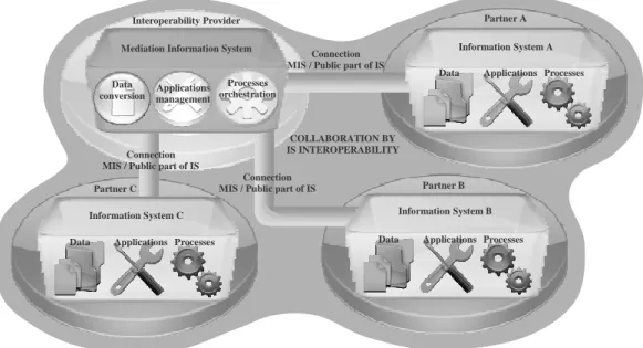
We believe that partners’ ISs can not assume natively those three functions (without a strong logic and technical standardization which seems to be too reducing). A Mediation Information System (MIS) seems to be a credible and pertinent way of supporting ISs interoperability as shown in next figure:
Fig. 1. Interoperability of Information Systems (through a Mediation Information System).
Finally, the MIS should be able to deal with the three functions identified below among a set of SOA partners’ ISs. It should so handle (i) the knowledge about partners’ data, (ii) a repository of partners’ services and (iii) the model of the collaborative process that should be run and the workflow engine able to run it.
1.2 General approach
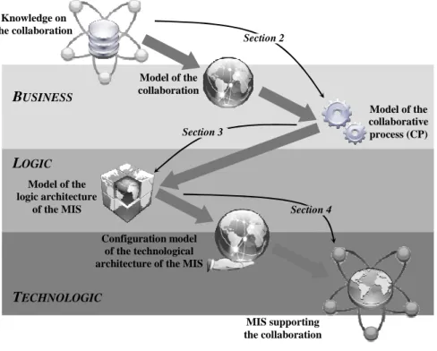
The global aim of this article is to propose a MIS design approach based on model-driven concepts, i.e. a dive across abstraction levels (business, logic and technologic),
Partner A
Partner B Partner C
Interoperability Provider
Mediation Information System Information System A
Information System B Information System C
Data Applications Processes Data Applications Processes
Data Applications Processes Data conversion Processes orchestration Applications management Connection MIS / Public part of IS
Connection MIS / Public part of IS
Connection MIS / Public part of IS
COLLABORATION BY IS INTEROPERABILITY
using tools such as model transformation and ontology (figure 2). Considering one particular collaborative situation, the proposed principle is to use the knowledge about that collaboration (enterprises involved, roles, topology of the network, services provided, goals, etc.) to instantiate a network ontology. Deduction rules can be applied on this collaboration model to propose a model of collaborative process (CP) as Computer Independent Model (CIM). Extracting the knowledge embedded into this model of CP, model morphism mechanisms can be applied (based on CP and MIS metamodels) in order to propose a model of the logic architecture of the adequate MIS as Platform Independent Model (PIM). Finally, using this logic model of MIS, a final step of transformation mechanism can be executed in order to obtain a technological configuration of the dedicated MIS as Platform Specific Model (PSM):.
Fig. 2. Global principle of MIS design through a Model-Driven Approach.
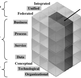
1.3 Positioning in Enterprise Interoperability Framework
The interoperability framework of InterOP is presented in [6] and is defined according to three major dimensions (which are not detailled here):
• Interoperability levels (Data, Service, Process and Business),
• Interoperability barriers (Conceptual, Technological and Organizational), • Interoperability approaches (Integrated, Unified and Federated).
The work presented below may be positioned according to the following figure:
TECHNOLOGIC
LOGIC
BUSINESS
Knowledge on the collaboration Model of the collaboration Model of the collaborative process (CP) Model of the logic architecture of the MIS Configuration model of the technological architecture of the MISMIS supporting the collaboration Section 2
Section 4 Section 3
Fig. 3. Position of the presented work into the enterprise interoperability framework of InterOp.
The chosen way to tackle interoperability issue is based on a common metamodel of IS (SOA): (i) it does not implies standards (not integrated) and (ii) it does not allow a complete freedom of models and languages (not federated). The approach is so Unified. Using collaboration models to align goals with proposed processes deals with Business level while the logic MIS metamodel deals with Process, Service (SOA) and Data (SOA). Finally, the CIM to PIM transformation concerns Organizational barrier (dynamic, responsibility, etc.) while the CIM to PIM and the PIM to PSM transformations concern Technological barrier (logic and physical architecture). Conceptual barrier is supposed to be already broken with the will of collaboration.
2 CIM Level
The first step of this work aims at using information about collaboration to build collaborative process model. This CIM design activity is based on a task of collaboration characterization using the Collaborative Network Ontology (CNO) [8]. This ontology includes two sub-ontologies connected by deduction rules: (i) Collaboration Ontology (CO) and (ii) Collaborative Process Ontology (CPO).
2.1 Collaborative Network Ontology
According to [9] and [10], an ontology is a suitable way for knowledge management: it is a formal and explicit description of concepts of a particular field or domain, of properties and characteristics of these concepts and of the relations between them. These concepts can be instantiated to create a concrete knowledge. From a graphic point of view, an ontology can be represented by a graph which nodes are concepts
Business Process Service Data Conceptual Technological Organizational Federated Unified Integrated Interoperability Approaches Interoperability Levels Interoperability Barriers Position of this article
(with their properties) and which links are relations between concepts. This structure allows semantic deduction on instances. The CNO is shown on next figure:
Fig. 4. Graphic representation of the Collaborative Network Ontology (CNO).
The CO concerns the characterization of collaborative network (common goal, relationship, topology) [11] and the characteristics of participants (role, abstract service, etc.). A collaborative network has participants and common goals. Common goal achieves abstract services. Participants play roles (e.g., seller, buyer, producer) and provide abstract services (e.g., marketing and sale, procurement). A network may have topologies (with duration and decision-making power) and contain relations.
The CPO is an extension of the concepts developed by the MIT Process Handbook project [12] and integrates a proposed CP metamodel [13]. Business service concept explains task at functional level (e.g., obtain order, deliver products, pay against invoice) and have input and output resources (e.g., machine, data). According to [12], two business services are dependent of each other if they have a common resource. Each dependency will be associated to a coordination service (e.g., manages flow). Which is a response to problems caused by dependencies. This means a coordination service manages a dependency. Coordination services are MIS services since MIS is defined as a mediation system managing the collaboration.
2.2 Deduction rules
Connections between ontologies (CO and CPO) can be identified via deduction rules. Rules are written in SWRL (Semantic Web Rule Language [14]) as antecedent-consequent pairs. Five groups of rules have been defined: (i) role and abstract service, (ii) business service, (iii) dependency, coordination service and CIS service, (iv) common goal, and (v) topology. Only the first three groups have been implemented. The next lines present three rules representing the three main group of rules:
Collaborative network Common Goal participant Abstract service chain P2P star kind Of topology role relationship competition Supplier-customer Group of interest power central equal hierarchic duration continuous discontinuous contain has has play achieve perform Is performed by provide has has P1 / P2 has Dependency b/w services of participants (message flow)
Dependency b/w CIS services (sequence flow) Coordination
service
Business service MISservice
generic specific resource consist of has input has output contain is a from to manage is coordinated by from to manage has has Collaboration Ontology (CO) one-to-one one-to-many Collaborative Process Ontology (CPO)
participant(?x) ∧ playRole(?x,?y) ∧ performAService(?y,?z) • provideAService(?x,?z)
Relation between role and activity is discussed in [15]. The aim of this rule of the first group is to derive abstract services when a role is provided. This rule can be explained for instance: if participant “A” plays role “seller” then the participant “A” provides abstract services “sell service”, “sell product”, “sell items from stock”, etc. However, this rule will run fine when each role in the knowledge base has already been predefined its corresponding abstract service.
participant(?x) ∧ provideAService(?x,?y) ∧ hasBusinessService(?y,?a) • provideBusinessService(?x,?a)
This rule from the second group, is interested in the deduction of business services when an abstract service is provided. For instance, if participant “A” provides abstract services “sell product” then the participant “A” provides also the business services “obtain order”, “prepare products to deliver”, “transfer invoice”, etc. However, this rule will run fine when each abstract service in the knowledge base has already been predefined its corresponding business services. The idea of separating two levels of services into abstract services and their related business services comes from [12]. CNetwork(?a) ∧ hasRelationship(?a,?z) ∧ P1(?z,?y) ∧ P2(?z,?x) ∧ provideBusinessService(?x,?b) ∧ hasInput(?b,?d) ∧
provideBusinessService(?y,?c) ∧ hasOutput(?c,?d) ∧ manageResource(?f,?d)
∧ Dependency_between_BusinessServices_of_Participants(?e) • fromBusinessService(?e,?c) ∧ toBusinessService(?e,?b) ∧
containResource(?e,?d) ∧ isCoordinatedBy(?e,?f) ∧ hasMISservice(?a,?f)
∧ MISservice(?f)
This rule from the third group aims at deducing dependencies when two business services have a common resource as discussed in [12]. For instance, if the “place order” service of a buyer produces a “purchase order” as output and the “obtain order” service of a seller uses a “purchase order” as input then a dependency between these two services is established. Once the dependencies known, coordination services can be deduced from dependencies. The relation between dependency and coordination is discussed in [16], while the fact that coordination service should be included into the MIS derives from [17]. For instance, if the dependency refers to the resource “purchase order”, then the coordination service which manages that resource is “manage flow of document” and is added into the MIS.
2.3 Supporting tools and application scenario
As we have discussed previously about the ontology and the deduction rules, this subsection will focus on the proposed tools to support the approach (including the ontology, and the rules). The following figure shows that the global architecture is composed of four parts: (i) knowledge gathering, (ii) knowledge base and deduction of collaboration pattern, (iii) extraction of collaborative process related to given collaboration cases, and (iv) BPMN relevant process. The schema below shows the four parts of the ontology-based approach with tools used at each part:
Fig. 5. Graphic representation of the Collaborative Network Ontology (CNO).
The current application covers the first three parts except the complements in the third part and the whole fourth part (this is a work in – good – progress):
Part 1: Knowledge gathering. The knowledge to gather can be divided into two parts: (i) characteristics of the studied network (relationships between participants, common goal, etc.), and (ii) participants’ details (roles, services, etc.). To gather the knowledge, a tool called Network Editor (NE) has been developed. It will be used to facilitate to define and characterize the collaborative network. Once the collaborative network model has been defined (network and partners), according to interviews and informal validation of all involved participants, the second phase can start.
Part 2: Knowledge base construction and collaboration pattern deduction. First, the knowledge base is created and populated with some individuals. The knowledge base contains only standard individuals (e.g. business services, roles, coordination services, etc.). Building this knowledge base requires an ontology which is the CNO. The CNO has been informally defined as discussed in the subsection 2.1 and is formalized with OWL (Web Ontology Language) using the tool Protégé© in order to construct a knowledge base [8]. The deduction rules, discussed in the section 2.2, are included as a part of the ontology [14]. The individuals come from the dataset, which is an “OWLized” version of [12] (which can be found at:
http://www.ifi.unizh.ch/ddis/ph-owl.html), and are stored in the knowledge base in their corresponding classes with their specific properties.
Second, the collaborative network characterized (thanks to the NE) is imported into the knowledge base as a set of new individuals. To be importable, this network model is transformed to an OWL model (accepted by Protégé©). This transformation is done using XSL (eXtensible Stylesheet Language). Once this importation done, deduction can be performed by executing the SWRL rules with the Jess© engine [14]: Jess is in charge of creating new OWL concepts and inserting them into the knowledge base.
Part 3: Specific collaborative process extraction. This part aims at creating a CP. SPARQL Queries are used to extract the collaboration patterns corresponding to the studied network. The set of obtained patterns is transformed into a CP using XSL. This CP is injected into a Collaborative Process Editor (CPE) using its own DSL2.
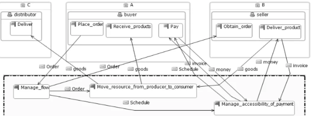
Fig. 6. An example of a collaborative process represented in CPE.
The produced CP (figure 6) is perfectible because: (i) some structuring elements are missing (such as gateway, events, etc.) and (ii) identified tasks are semantically linked with the Process Handbook (and not with the real services of partners).
Part 4: BPMN collaborative process construction. To obtain the BPMN model expected at the CIM level, a transformation of the obtained CP model (based on CPE) into a CP model (based on BPMN) is needed (figure 7). The transformation language used is Atlas Transformation Language (ATL) [18], [19] which is QVT (Query, View and Transformation) compatible. QVT is an OMG specialized language.
Fig. 7. Transformation of a CP modeled with CPE into a CP modeled in BPMN (using ATL).
Transformation rules are globally simple, due to the semantic proximity of the source language (CPE DSL dedicated to CP modeling) and target language (BPMN).
2 Domain Specific language: Custom graphical designer built on the fly for one specific field. ATL Transformation World
XML File of the CP (in CPE)
Ecore File of the CP (in BPMN) Transformation rules (model morphism) Transformation mechanism BPMN CP Metamodel CPE CP Metamodel
CPE
BPMN
Editor
3 PIM Level
The obtained CIM (according to section 2) is dedicated to provide the formalized knowledge about the collaboration to be. The objective of the PIM level is to use that knowledge to build (in UML) a logic model of the adequate mediation IS (the PIM of the MIS). The relevant question is the following: is the knowledge embedded into the BPMN process model, of the CIM level, a sufficient and significant knowledge to build a logic model of the adequate mediation information system in UML? Based on [20] and [21], this discussion is done in [22] and conclude that, if partners’ services and data (concerned by the collaboration) are correctly identified, it seems that a BPMN collaborative process model might be significant to build a UML model of the logic view of a mediation information system.
3.1 Involved Metamodels
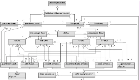
The next figure represents the source metamodel of collaborative process:
Fig. 8. Metamodel of collaborative process in BPMN.
The collaborative process metamodel is composed with the following elements: • BPMN process: this abstract class represents a model respecting BPMN grammar,
• Collaborative process: this class inherits from the abstract class BPMN process, • Partner pool: this class represents a partner,
• CIS pool: this class represents the MIS,
• Partner lane: this class represents a subdivision of a partner, • CIS lane: this class represents a subdivision of the MIS,
• Message flow: this class transfers a data between a partner pool and the CIS pool, • Sequence flow: this class transfers a data between elements of the CIS pool, • Partner task: this class represents a task of a partner (one of its services),
• CIS task: this class represents a task of the MIS (one of its services),
• Start / intermediate / end event, gateway, sub-process: BPMN modeling basics. • CIS component: this abstract class represents each element of the CIS pool. • mf IN and mf OUT: these classes are the extremities of a Message flow, • sf IN and sf OUT: these classes are the extremities of a Sequence flow,
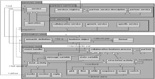
The target MIS metamodel (figure 9) is based on the PIM4SOA model [23]. Three packages are proposed corresponding to three views of the final result:
• Services view: services (from MIS or partners) used in the collaboration. They are business reachable computing functionalities with location. This view includes:
• Service, operation: services (abstract) and their functional elements, • Partner services: this package contains a service registry referring to
partner service and their partner service description, • CIS services: this package includes collaborative services.
• Information view: data that are exchanged between services. Their structure is defined as well as their emission and reception services. This view includes:
• Business object: this class represents a data exchanged between services, • Format, semantic definition: these classes document a business object. • Process view: scheduling and coordination of services. This view includes
elements of workflow modeling (partially based on BPEL modeling).
Fig. 9. Metamodel of SOA Mediation Information System in UML.
3.2 Transformation mechanism
The transformation language used here (from BPMN collaborative process to UML SOA Mediation Information System) is, as for the CIM level, ATL [18], [19].
Fig. 10. Transformation of a BPMN CP into an UML SOA MIS (using ATL tool).
Transformation rules are not trivial, due to conceptual differences between the two considered worlds (business and CIM logic architecture) and are of two kinds: • Mapping rules: rules applied first to build MIS logic elements from CP elements, • Called rules: rules applied secondly to link MIS logic elements.
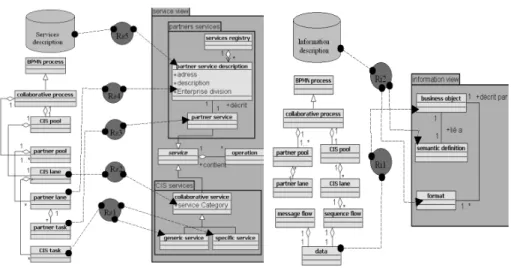
Fig. 11. Mapping rules for basic generation of the service view and the information view.
On figure 11, rules are represented by circles in the middle of two class diagrams which are parts of the primitive metamodels: source (left) and target (right).
The service view of the MIS model is represented in figure 11 (left part). Pool and lane classes are mapped on the different services required (partners or CIS services). Rs1 rule gives the links from tasks in the CP model to services listed in the registries (specific or generic). Rs2 to Rs5 rules provide solutions for the structure of services.
With the same logic, figure 11 (right part) introduced two transformation rules applied for the information view. Transformation provides syntactic indications that helps to create business objects (Rules Ri1 and part of Ri2). However, the problem of translation refers to semantic interpretation that we do not include in this part of the study (Remaining part of Ri2 is probably not a robust solution).
UML
ATL Transformation World
XML File of the CP (in BPMN)
XML File of the MIS (in UML)
Transformation rules (model morphism) Transformation mechanism UML Metamodel BPMN CP Metamodel
BPMN
MIS SOA BPMN CP SOA+
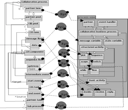
SOA UML ProfileIn contrast, figure 12. is the most developed part of the transformation procedure. The process view package has been designed using specifications of the BPEL meta model. BPEL is massively used for specification of web services process execution. Some of the rules in figure 12 are adaptations of recommendations provided by BPMI when they address the problem of BPMN graph conversion to BPEL well defined XML sentences [24], [25]. It concerns rules Rp3 to Rp6, and rules Rp8 to Rp9. Rules Rp1, Rp2 and Rp7 participate to the definition of coordination activities.
Fig. 12. Mapping rules for basic generation of the process view.
Three called rules (Rb1 to Rb3) are given in the following as an example.
• Rb1 : sequence ordering. A sequence element issued from Rp3 rule is associated with two basic activities into the same process package.
• Rb2 : information processing. A service from service package is related to a business object of the information package.
• Rb3 : service identification. A basic activity of the process package is linked to a service of the service package.
4 Perspectives
Three main parts have to be completed in order to complete the results presented below: (i) mapping between identified services and real business services (ii) PSM Level, and (iii) agility of the MIS.
4.1 Mapping between identified services and real business services
The CP model obtained at the CIM level synchronizes tasks which have been identified form the Process Handbook [12]. However, these tasks are the ones used to generate (through the ATL transformation tool) the MIS logic model which refers to partners’ services. That is why a semantic step has to be added in order to identify from the generic Process Handbook tasks of the collaborative model in BPMN the specific services of partners which will be referenced into the MIS logic model.
This step is not a trivial one but it is important to realize how much the obtained CP model facilitates it: indeed, the structure of the BPMN model provides to each partner the precise subset of the generic Process Handbook it has to share in order to ensure the expected behavior of the network. Furthermore, these generic services are “atomic”, that is to say that they are precisely identified at a low level of granularity. Thus, if that step could not be fully automated, the manual way would be acceptable.
4.2 PSM Level
The logic model of the MIS, obtained at the PIM level, is not dedicated to one specific technological architecture. The next step is so to identify this target physical system to build its metamodel in order to drive an ATL transformation (like between the CIM and PIM levels. Indeed, once thetechnical architecture known (which should of course respect SOA principle), the projection of the PIM logic model will be based on model morphism and mappings between logic components and technological components. We believe that the semantic proximity of these two architectures (logic and technological), partially due to the SOA constraint, will facilitate this step.
Furthermore, the target technological architecture has been identified with EBM Websourcing: PEtALS3 Enterprise Service Bus is an adequate technical solution to support the proposed MIS. We are currently working on the model of that ESB in order to propose the transformation mechanism adapted to this PSM level.
4.3 Agility of the MIS
An industrial network is not a stable and permanent entity. Partners may leave or join the collaboration. The ability of such a network to stay efficient and to evolve with internal or external variations is a firm factor of quality and maturity. The French project ISyCri (Interoperability of System in Crisis situation [26]) tries to propose several stages of looping which would improve flexibility of a collaborative network: (i) a global loop concerning the CIM level which oblige to restart the whole process (collaboration characterization, CP modeling, MIS logic modeling and physical projection) due to major modifications (based on measure of distance between the current model and the objective situation), (ii) an intermediate loop centered on the workflow definition which allows to modify the process without changing the collaboration characterization, and (iii) a short loop dedicated to technical
orchestration of the workflow and the capacity of the MIS to suspend, modify or abort a dynamic in order to reroute or adapt the workflow (based on human instructions).
5 Conclusion
The following picture illustrates the global position of the results and perspectives presented in this article:
Fig. 13. Global overview of the article.
The classical “Y” of the Model-driven approach has been subdivided in order to add the logic metamodeling induced by the model transformation step at the PIM level.
References
1. Konstantas, D., Bourrières, J.-P., Léonard, M., Boudjlida, N.: Preface of : Interoperability of Enterprise Software and Applications. In: INTEROP-ESA’05 Interoperability of Enterprise Software and Applications, pp. v-vi. Springer, Geneva, Switzerland (2005)
2. Vernadat, F.: Interoperable enterprise systems: architecture and methods. Plenary lecture, IFAC/INCOM conference, Saint-Etienne (2006)
3. Morley, C., Hugues, J., Leblanc, B.: UML pour l’analyse d’un système d’information. 2nd edition, Dunod, France (2002)
PIM CIM
Business model of the collaborative process
(BPMN)
Logic metamodel of the SOA MIS (Ecore)
LM
Logic model of the SOA MIS (UML)
Physical architecture of the target system
Technological model of the MIS
(ESB PEtALS)
PM
PSM
Business branch Logic branch Technological branch
Technological projection (MIS urbanization) Translation CIM Level (Section 2) PSM Level (Section 4) PIM Level (Section 3) Logic / Technologic consistency
4. Bénaben, F., Touzi, J., Rajsiri, V., Pingaud, H.: Collaborative Information System Design. In: AIM 2006 Information Systems and Collaboration: State of the Art and Perspectives, pp 281-296. GI-Edition, Lecture Notes in Informatics (2006)
5. Aubert, B., Dussart, A.: SI Inter-Organisationnels. In: CIRANO Bourgogne report (2002) 6. Chen, D., Dassisti, M., Elvaester, B.: Interoperability Knowledge Corpus, Intermediate
Report. Deliverable DI.1b, Network of Excellence InterOp, Contract No.IST-508011 (2006) 7. Miller, J., Mukerji, J.: MDA Guide V1.0.1. OMG document No. omg/2003-06-01 (2003) 8. Rajsiri, V., Lorré, J.-P., Bénaben, F., Pingaud, H.: Contribution to the knowledge-based
methodology for collaborative process definition: Knowledge extraction from 6napse platform. In: INTEROP-ESA’08 Enterprise Interoperability III, pp. 437-450. Springer, Berlin, Germany (2008)
9. Dieng, R.: Knowledge Management. Dunod, Paris, 3rd edition (2005)
10. Missikoff, M., Taglino, F.: Ontologies for interoperability: a systematic overview. Lecture in ECI Workshop, Paris (2006)
11.Rajsiri, V., Lorré, J.-P., Bénaben, F., Pingaud, H.: Cartography based methodology for collaborative process definition. In: ProVE’07 Establishing the Foundation of Collaborative Networks, pp. 479-486, Springer, Portugal (2007)
12.Malone, T. W., Crowston, K., Herman, G. A.: Organizing business knowledge – the MIT Process Handbook, MIT Press (2003)
13.Touzi, J., Bénaben, F., Lorré, J.-P., Pingaud, H.: A Service-Oriented Architecture approach for collaborative information system design. In: Proceedings of IESM’07, Beijing, China (2007)
14.O’Connor, M., Knublauch, H., Tu, S., Grosof, B., Dean, M., Grosso, W., Musen, M.: Supporting rule system interoperability on the Semantic Web with SWRL. In: Proceedings of ISWC’05, Galway, Ireland (2005)
15.Petersen, S.-A.: The role of enterprise modeling in virtual enterprises. In: Collaborative Networks and their Breeding Environments, Springer (2005)
16.Crowston, K.: A Taxonomy of Organizational Dependencies and Coordination Mechanisms. Working paper No. 3718-94, Massachusetts Institute of Technology, Sloan School of Management (1994)
17.Touzi, J., Bénaben, F., Lorré, J.-P., Pingaud, H.: Interoperability through model based generation: the case of the Collaborative IS. In: INTEROP-ESA’06 Enterprise Interoperability, pp. 407-416. Springer, Bordeaux, France (2006)
18.Bézivin, J., Dupé, G., Jouault, F., Pitette, G., Rougui, J.-E.: First Experiments with the ATL Model Transformation Language: Transforming XSLT into Xquery. In: Proceedings of OOPSLA’03, Anaheim, USA (2003)
19.Jouault, F.: Contribution à l'étude des langages de transformation de modèles. PhD Thesis, Université de Nantes (2006)
20.Vernadat, F.: Enterprise Modelling and Integration. Chapman & Hall (1996)
21.Booch, G., Jacobson, I., Rumbaugh, J.: UML 2.0 Guide de reference. CampusPress (2004) 22.Touzi, J., Bénaben, F., Pingaud, H.: Model Transformation of Collaborative Business
Process into Mediation Information System. Accepted paper for IFAC’08, to be published, Seoul, Korea (2008)
23.Benguria, G., Larrucea, X., Elvaester, B., Neple, T., Beardsmore, A., Friess, M.: A Platform Independent Model for Service Oriented Architecture. In: INTEROP-ESA’06 Enterprise Interoperability, pp. 407-416. Springer, Bordeaux, France (2006)
24.BPMI. Business Process Modeling Notation (BPMN), Version 1.0. (2004)
25.Ouyang, C., Van Der Aalst, W., Dumas, M., Hofstede, A.: Translating BPMN to BPEL. In: technical report – BPM group, Queensland University of Technology, Brisbane (2006) 26.Truptil, S., Bénaben, F., Couget, P., Lauras, M., Chapurlat, V., Pingaud, H.: Interoperability
of IS in Crisis Management: Crisis Modeling and Metamodeling. In: INTEROP-ESA’08 Enterprise Interoperability III, pp. 583-594. Springer, Berlin, Germany (2008)