Multidisciplinary Design Optimization of Hydrogen
Peroxide Monopropellant Propulsion System using GA
and SQP
Amirhossein Adami
Amirkabir University of Technology, PhD student Hafez Street, Tehran, Iran
Mahdi Mortazavi
Amirkabir University of Technology, Hafez street, Tehran, Iran
Mehran Nosratollahi
Space Research Institute 24th kilometer of Tehran-Karaj
highway, Tehran, Iran
ABSTRACT
An intense simplification in production, storage and handling of hydrogen peroxide develop a renewed interest in hydrogen peroxide thrusters especially for low cost attitude control or orbit correction (orbit maintenance). Chemical decomposition, aerothermodynamics flow and structure demand different optimum conditions such as tank pressure, catalyst bed pressure, concentration of H2O2 and geometry. These parameters play important role in propulsion system’s mass and performance. Discipline conflicts are solved by Multidisciplinary Design Optimization (MDO) techniques with synchronized optimization for all subsystems respect to any criteria and limitations. In this paper, monopropellant propulsion system design optimization algorithm is presented and result of the design algorithm is validated. Results of the design algorithm have been compared with data of two different operational thrusters. According to the results, the proposed model can suitably predict total mass and performance with errors below than 10%. Then, MDO framework is proposed for the monopropellant propulsion system. Optimum propellant mass, thrust level, mass flow rate, nozzle geometry, catalyst bed length and diameter, propellant tank mass, feeding subsystem mass and total mass are derived using hybrid optimization (GA+SQP) for two space missions.
Keywords
Multidisciplinary Design Optimization, MDO GA, SQP, Monopropellant Propulsion, Hydrogen Peroxide
1.
INTRODUCTION
The need of less toxic propellants has developed a renewed interest in using hydrogen peroxide engines. The use of hydrogen peroxide (H2O2) as an oxidizer in bipropellant liquid rocket engines [1] as well as in hybrid rocket engines is interested [2]. The general applications of hydrogen peroxide could be fund in reusable launch vehicles and upper stages [3]. The use of H2O2 as a monopropellant was widely used in the 50s and 60s, but it was progressively replaced by better propellants such as hydrazine. However, because of the toxic and carcinogenic nature of hydrazine, interest has recently grown into alternative, less-toxic propellants [4]. Wide range application of H2O2 monopropellant thrusters could be found for small satellite and rockets [5] [6]. Attitude control and orbit correction are most application of H2O2 thrusters in small satellite but deorbit propulsion system of reentry vehicle is also mentioned. Resent researches on H2O2 thrusters are generally focused on improving in decomposition and low cost catalyst production [7] [8] [9] [10].
[image:1.595.318.537.378.452.2]Specific impulse (Isp) generally is considered as the performance of propulsion system. At this view, hydrogen peroxide as a monopropellant has lower performance about 20% in comparison with hydrazine, but the volume specific impulse achievable with 90% H2O2 is higher than the other propellants due to its high density [11]. Furthermore, with respect to other high-energy green propellants, like ADN, HAN [12] and HNF [13], decomposition temperature of hydrogen peroxide does not need high temperature materials and manufacturing processes for the thrust chamber. The mentioned notes are particularly useful for small satellites propulsion system. Figure (1) shows configuration of H2O2 monopropellant propulsion system.
Figure 1: Monopropellant propulsion system Higher Isp needs higher pressures and higher nozzle lengths. This condition leads to have heavier structure mass. Although propellant mass should be increase (because of increase in empty mass), but increase in Isp demands lower propellant mass. In view of the system level, optimum condition is related to minimum total mass of propulsion system (empty mass + propellant mass). It means that optimum Isp value is not maximum value and optimum empty mass is not minimum value. These conflicts should be managed to reach the optimum point for every parameters and disciplines. Multidisciplinary design optimization (MDO) techniques such as All At Once (AAO), Collaborative Optimization (CO), Bi-Level Integrated System Synthesis (BLISS) and Concurrent Subspace optimization (CSSO) solve these conflicts. In this paper, every discipline is developed based on AAO framework. AAO is the most basic MDO technique and has wide industry acceptance [14].
2.
PROPELLANT SPECIFICATION AND
DECOMPOSITION PROCESS
The governing reaction equation for the decomposition process involving H2O2 is given in equation (1).
(1)
2 2 2 2
2H O l( )Catalyst 2H O g( )O g( )Heat
Equation (1) shows that only the superheated steam and oxygen are released from decomposition process. It means that no other toxic gas is released to the air [15]. Temperature and physical-chemical property of production of decomposition are strongly correlated to the concentration of H2O2. Equation (1) is represented as equation (2).
(2) 2 2
(1
)
2 2 22
x
xH O
x H O
H O
O
Where, x is molar percentage of the concentration of H2O2. Table (1) presents properties of H2O2 decomposition products.
Table (1): physical-chemical property of H2O2
concentration of
H2O2 85% 90% 95% 98%
Adiabatic Temp.(k) 907 1029 1151 1225 Molecular mass 21.83 22.10 22.39 22.56
1.2751 1.2647 1.2557 1.2509Density (
kg
3m
) 1340 1360 1380 13923.
PROPELLANT TANK MODELING
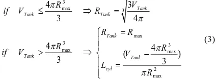
Although spherical tanks have a lower mass in comparison with cylindrical types, but cylindrical tanks demand lower diameter and simpler production procedures. Propellant tank configuration is limited with maximum permitted diameter. If spherical tank cannot provide the require volume, cylindrical tank with maximum permitted diameter and suitable length is considered. Equation (3) presents the method of configuration selection related to the required volume.
(3) 3 max 3 max 3 3 max max 2 max 4 3 3 4 4 4 ( ) 3 3 Tank Tank Tank Tank Tank Tank cyl R V
if V R
R R
R R
if V V
L R
Mass of propellant tank is related to tank pressure, tank configuration, filling factor, propellant concentration and propellant mass. Aluminum or titanium structures are generally used for space application but lower cost of aluminum provides more interest. Propellant tank mass is estimated by equation (4).
(4) 2
.
(4
2
)
,
2
Tank
Tank Tank Tank cyl str Tank
Sph S F cyl Sph
Tank Tank Tank Tank
str
M
R
R
L
n
P
R
2
p
p
r d
d
d
d
s
=
+
=
=
[image:2.595.49.288.288.461.2]Input-output data of propellant tank model has been finally presented in figure (2).
Figure 2: Input-Output flow data of propellant tank model
4.
PRESSURIZED FEEDING
MODELING
Feeding subsystem should produce the safe continuous or discontinuous propellant flow to the catalyst bed (thruster). A separate gas supply pressurizes the propellant tank to force H2O2 flows on the catalyst bed. Pressurizer gas supply with or without regulator is usually used for low required mass flow such as monopropellant thruster. Turbo-pumps are used for high thrust level and mass flow such as bipropellant propulsion systems. Constant thrust level is usually required in conceptual design phase. Constant thrust level needs constant feeding pressure thus; regulator is used to keep the propellant tank pressure near the desire values. Feeding subsystem consists of feed line (tubes and ducting), regulator, valves, gas tank and pressurizer gas. Some of these components can be vanished in conceptual phase because of same effect in various concepts. Most part of feeding subsystem mass (changing by concepts) connected to the gas tank and pressurizer gas. Propellant tank volume and feeding pressure specify the feeding subsystem geometry and mass. Required radius of gas tank is derived by equation (5). Complete modeling of the pressurized feeding subsystem can be found in [16].
(5)
( 0) ( 0)
. . . . ( 0) . max max ( 0) . 3 . ( )
(
( ))
3
4
t tP G Press Gas P G Press Gas t Press Tank t Press Tank Press Tank total total
M
M
RT M
M
V
P
P
RT
V
R
Titanium structure is selected for pressurized tank because high pressure demands thicker structure and mass penalty of aluminum utilization is considerable. Feeding subsystem mass is estimated by equation (6).
(6)
. .
2
. . .
.
. max .
3 max . . .
~ 0
4
4
3
feeding P T P g Others
Others
P T P T str P T
S F
P T P T
str
P g P T str
gas P g
M
M
M
M
M
M
R
n
P
R
2
P
M
R
R T
[image:2.595.60.273.555.633.2]Input-output data of feeding subsystem modeling is presented in figure (3).
[image:2.595.319.535.705.745.2]5.
THRUSTER MODELING
Thruster consists of catalyst, catalyst bed (similar to combustion chamber) and nozzle. Thruster design is one of the most important parts of every propulsion systems and optimization procedure of propulsion system is often limited only to optimization of the thruster’s performance. Thrust level and Isp introduce the thruster size and performance respectively. The mentioned parameters are calculated by equation (7). Steel structure is commonly used for the thruster.
(7) 1
2 2( 1)
2 2
0
(
1)
2
1
1
1
2
e e vac e e vac vacA P
M
T
M
M
T
Isp
mg
5.1
Catalyst
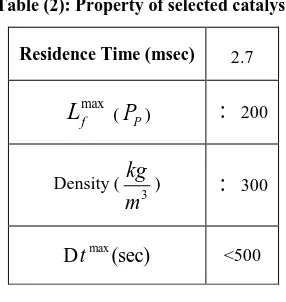
The most significant technology challenge of hydrogen peroxide monopropellant thrusters is the development of new effective catalyst. Nowadays, the most used catalyst materials for H2O2 are metallic silver, MnO2 and Mn2O3 and alumina-deposited platinum. Although peroxide hydrogen catalysts are not completed like a hydrazine catalyst (shell 405) but some suitable ones are known and developed base on composite silver catalyst [17]. Similar catalyst is considered in this study. Most important characteristics of the catalyst are ability to decompose the propellant flow (named catalyst bed loading) and longer activity. Table-2 shows some physical parameters of the considered catalyst.
Table (2): Property of selected catalyst Residence Time (msec) 2.7
max f
L
(P
P):
200Density ( 3
kg
m
):
300max
(sec)
t
D
<5005.2
Catalyst bed
Length and diameter of the catalyst bed introduce the geometry. Maximum pressure of the catalyst bed specifies required thickness of thruster. Important event in catalyst bed is pressure drop during the injection and movement through the catalyst bed. Three more important losses between propellant tank and thruster included pipe and feeding pressure drop, injector pressure drop and catalyst pressure drop. Equation (8) shows the relation between propellant tank pressure and thruster pressure [16] [18]. According to the equation (8) it is clear that catalyst bed length and radius are depended on mass flow and pressure of the thruster.
(8)
2 2 2 2
Tank Tank 2 2 2
0.5
0.15(
)
6
(
)
(
)
75
1.2
1.5
120
0
2
Th ctl inj pipe
pipe
inj pipe
ctl ctl
ctl residence
inj
inj Th residence inj
inj inj
H O H O
P
P
P
P
P
P
bar
P
P
P
P
bar
L
mm
L
V t
V
V
Cd P
t
Cd
V
V
5.3
Divergent-Convergent Nozzle
[image:3.595.332.521.70.224.2]High pressure and temperature flow exits from the catalyst bed and enters the D-C nozzle. It changes the potential energy to the kinetic energy. Conical nozzle is selected for conceptual design phase. Divergence half angle of the cone, catalyst bed diameter, throat diameter, convergence half angle of the cone and exit diameter are introduced the nozzle geometry. The nozzle geometry is illustrated in figure (4).
Figure 4: Nozzle Geometry Parameters
These geometry parameters correlate with thermodynamic parameters. Equation (9) presents the relation of geometry parameters and thermodynamic parameters.
(9) 1 2 1 2( 1) 1 2( 1) 2 1 2
45 , 15
1 (1 ) 2 2 1 1 1 2 , tan tan c Th
e e expansion
e
ctl t e t
div div T R m A P A
A M A Z
M
R R R R
L L
Exit pressure of the nozzle can be chosen near 0.01 (bar) for space applications but optimum value is introduced by the nozzle expansion ratio in the optimization procedure. Total thruster mass (catalyst, catalyst bed and nozzle) is estimated from equation (10).
(10) 2
2 2 2 2
1 2 2 . (2 ) [ ( ) ( )] tan tan ( )
Thruster Comb Nozzle cat Comb ctl ctl ctl Comb str
Nozzle ctl t e t Comb str
S F Th ctl Comb
str ctl
cat ctl c ctl
M M M M
M R L R
M R R R R
n P R T
R
M A L
p p d r
p p d r q q p d s p r = + + = + = - + -+ = =
[image:3.595.95.238.403.554.2]Figure 5: Input-Output flow data of thruster
6.
VALIDATION OF DESIGN
ALGORITHM
Modeling of each part of the propulsion system should be complex enough to properly estimate the propulsion mass, geometry and performance. Results converge to the real thruster’s data by using some correction factors. The correction factors (and related suitable values) are proposed as follow.
(11) 1
0 0
2
1
2 .
(
)
0.95
0.81
1.25
real Ideal
real A diabatic
Total Thruster feeding Tank
Nozzle Correction Factor
A diabatic Temp Correction Factor
Other Equipments
Thrust
Thrust
T
T
M
n
M
M
M
n
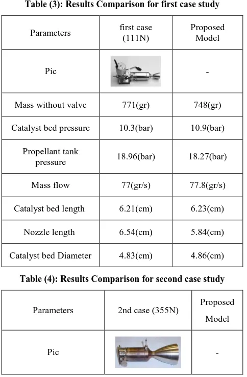
For example, comparison between two real thruster’s data and the proposed model are summarized at table-3 and table-4. It should be noted that table-3 and table-4 shows the redesign results only and no optimization has been done yet.
Table (3): Results Comparison for first case study Proposed
Model first case
(111N) Parameters
-Pic
748(gr) 771(gr)
Masswithout valve
10.9(bar) 10.3(bar)
Catalyst bed pressure
18.27(bar) 18.96(bar)
Propellant tank pressure
77.8(gr/s) 77(gr/s)
Mass flow
6.23(cm) 6.21(cm)
Catalyst bed length
5.84(cm) 6.54(cm)
Nozzle length
4.86(cm) 4.83(cm)
Catalyst bed Diameter
Table (4): Results Comparison for second case study Proposed
Model 2nd case (355N)
Parameters
- Pic
892(gr) 907(gr)
Mass without valve
10.9(bar) 10.3(bar)
Catalyst bed pressure
18.27(bar) -
Propellant tank pressure
249(gr/s) 277(gr/s)
Mass flow
6.32(cm) 6.61(cm)
Catalyst bed length
9.39(cm) 11.11(cm)
Nozzle length
4.58(cm) 4.83(cm)
Catalyst bed Diameter
According to the results of table-3 and table-4, the proposed model has acceptable accuracy in mass modeling (
2%
Error ) tank pressure estimation (Error4%), thruster pressure estimation (Error6%) and mass flow estimation (Error10%).
7.
MULTIDISCIPLINARY DESIGN
OPTIMIZATION OF H
2O
2MONOPROPELLANT PROPULSION
SYSTEM
Lower specific impulse (Isp) is one of the disadvantages of hydrogen peroxide in comparison with hydrazine thrusters but higher propellant density which needs smaller propellant tank and feeding system may compensate this disadvantage. Integrated design algorithm could be more simplified by adjusting the flow data base on AAO framework. Important system outputs are recognized as the total mass, Isp and geometry (diameter and length). Minimum system inputs are introduced as thruster’s pressure, expansion ratio, propellant mass, concentration of H2O2, bed-loading and thrust level. Constants included structure materials (titanium, aluminum and steel) and pressurizer gas properties (He).
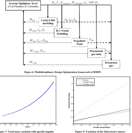
Figure (6) illustrates the multidisciplinary design optimization algorithm for monopropellant propulsion system based on AAO framework. Space missions are always optimized for lowest cost. Total mass is usually considered as the cost function in space missions. In addition, it has been proofed that lower required impulse (optimum maneuvers) leads to have better mission cost and mass. It should be mentioned that the same accessible impulse can be provided by many propulsion systems (various thrust level and propellant mass). In this paper, thrust level is also selected as a design variable to derive a global optimum solution. The required impulse (
req
V
V
) is considered as a system equality constraintsand maximum permitted diameter (
D D D
c,
e,
P T.
D
max ) is considered as a system inequality constraints. [image:4.595.47.289.389.758.2] [image:4.595.48.287.403.760.2]Figure 6: Multidisciplinary Design Optimization framework of HMPS
[image:5.595.57.277.544.732.2]Figure 7: Total mass variation with specific impulse
Figure 8: Total impulse variation with thruster’s pressure
Figure 9: Variation of the Subsystem's masses According to the results, for constant thrust level, increase in thruster’s pressure leads to have higher accessible total impulse (advantage) but leads to have heavier dry propulsion mass (disadvantage).
7.1
Hybrid Optimization Algorithm
To show the optimization results of HMPS, two space missions are considered for a satellite with the mass of 40 kg. The goal is to design an optimum HMPS for the satellite. The optimization variables and related bounds are introduced as follow.
(12)
2 2 2 2
2 30 , 1 500
10 500 , 100 50
85% 95% , 70( ) 200( )
. .
Th
expansion propellant
f
bar P bar N T N
Z gr M km
kg kg
H O L
m s m s
Equality and inequality constraints considered as follow for the two space missions.
150 155 160 165 170 175 180 185 190 195 200 0
0.5 1 1.5 2 2.5 3
Isp(s)
E
n
g
in
e
M
a
s
s
(K
g
)
10 20 30 40 50 60 70 80 1600
1650 1700 1750 1800 1850 1900 1950 2000 2050 2100
Thruster Pressure(bar)
T
o
ta
l
Im
p
u
ls
e
(N
.s
)
10 20 30 40 50 60 70 80 0
0.2 0.4 0.6 0.8 1 1.2 1.4
Thruster Pressure(bar)
S
u
b
s
y
s
te
m
M
a
s
s
(K
g
)
(13) max
max max
: 1000 ( / ) , 20
: 200 ( / ) , 10
500
req req
First Case V m s R cm
Second Case V m s R cm
t s
Genetic Algorithm (GA) and SQP are applied to derive the optimum solution of monopropellant propulsion system. Following inputs are used in GA:
Population size: 100
Number of generations: 50
Mutation probability: 0.6 (Floating point)
Cross-over probability: 0.4 (Floating point)
Mutation type: Adaptive feasible
Cross-over type: Two point
Selection: Roulette
[image:6.595.321.541.119.332.2]SQP is used to find the global optimal solution after GA. The optimization is done for the both mentioned missions. Figure (10) and figure (11) show the optimization procedures for the first case.
[image:6.595.61.278.325.514.2]Figure 10: Optimization Procedures of MDO for GA Elapsed time is equal to 12.41 seconds and F-count is equal to 1400 for GA. Mass of the best solution is equal to 55.42 kg.
Figure 11: Optimization Procedures of MDO for SQP
[image:6.595.317.538.399.617.2]Elapsed time is equal to 3.9 seconds and F-count is equal to 330 for SQP. Mass of the best solution of SQP is equal to 50.08 kg. Figure (12) and figure (13) show the optimization procedures for the second case similarly.
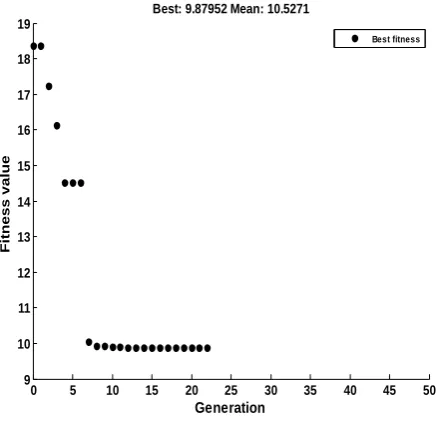
Figure 12: Optimization Procedures of MDO for GA Elapsed time is equal to 4.8 seconds and F-count is equal to 1150 for GA. Mass of the best solution of GA is equal to 9.8 kg.
Figure 13: Optimization Procedures of MDO for SQP Elapsed time is equal to 2.7 seconds and F-count is equal to 426 for SQP. Mass of the best solution of SQP is equal to 6.93 kg. The results of both optimum systems are summarized in table-5.
0 5 10 15 20 25 30 35 40 45 50
50 52 54 56 58 60 62 64 66 68 70
Generation
Fitness value
Best: 55.421 Mean: 68.5332
Best fitness
0 5 10 15 20 25 30
50 51 52 53 54 55 56
Iteration
Function value
Current Function Value: 50.0769
0 5 10 15 20 25 30 35 40 45 50
9 10 11 12 13 14 15 16 17 18 19
Generation
Fitness value
Best: 9.87952 Mean: 10.5271
Best fitness
0 5 10 15 20 25 30 35 40
6.5 7 7.5 8 8.5 9 9.5 10
Iteration
Function value
[image:6.595.56.268.566.743.2]Table (5): Optimum configurations for two cases
sp
I
(s) totalM
(kg) propellantM (gr) Expansion
ratio (area) Active
time (sec)
& Thruster Thruster
D L
(mm) Thrust
(N) max
feeding
P
(bar) inject
P
(bar) TankP
(bar)169.5 50.08
40.69 491
294.15 29.7*29.2
230.05 11.09
4.61 5.10
Case-1
171.3 6.93
5.26 95.68
500.00 8.18*29.4
18.63 11.42
3.96 5.16
Case-2
According to the results, concentration of H2O2 and bed-loading have similar affect in the design optimization procedures. Using higher concentration of H2O2 leads to have higher decomposition temperature and higher density. These events lead to have higher
I
sp and lower total mass. Higher bed-loading factor leads to have lower thruster diameter and lower structure mass. Optimum value of Lf is 200 and optimum value of concentration of H2O2 is 95%. Therefore, these two parameters are not necessary to be considered as the design variables at future.8.
SUMMARY AND CONCLUSION
In this paper monopropellant propulsion system is broken down to three more important subsystems including propellant tank subsystem, pressurized feeding subsystem and thruster subsystem (catalyst, nozzle and catalysts bed). Multidisciplinary design optimization of monopropellant propulsion system has been proposed. The proposed algorithm can be used for every pressurized feeding propulsion system such as bipropellant propulsion system without turbo pumps. For every required impulse, optimum propellant mass, thrust level, mass flow, nozzle geometry, catalyst bed length and diameter, propellant tank mass, feeding subsystem mass and total mass of propulsion system are optimized using hybrid optimization algorithm. Combination of GA and SQP can find the optimum solution in short elapsed time. According to the results, bed-loading (catalyst) and concentration of H2O2 (propellant) should be selected as maximum values to have a better propulsion system. Higher thrust levels are required for higher required impulses. The proposed model can be used for bipropellant propulsion systems that use H2O2 as an oxidizer but cost function of the model should be changed to maximizing the mass flow or decomposition temperature. As future works, blow down feeding can be considered and related equation will be developed.
9.
REFERENCES
[1] Design specifications of H2O2/kerosene bipropellant rocket system for space missions. Yongjun Moona, Chul Park,Sungkwon Jo,Sejin Kwon. Issue1,Pages 118–121, Aerospace Science and Technology, February 2014, Vol. 33.
[2] An Application of Commercial Grade Hydrogen Peroxide for Hybrid/Liquid Rocket Engine. Tsujikado, N., Koshimae, M., Ishikawa, R., Kitahara, K., Ishihara, A., Sakai, Y., and. Indianapolis, Indiana : 38th AIAA/ASME/SAE/ASEE Joint Propulsion Conference & Exhibit 7-10 July , 2002. AIAA paper 2002-3573. [3] Deign and Testing of an Upper Stage Hybrid Propulsion
System Using Hydrogen Peroxide Oxidizer. A. S. Prince, R. L. Carpenter, T. A. Boardman. Huntsville, Alabama : 38th AIAA/ASME/SAE/ASEE Joint Propulsion Conference & Exhibit, 2002.
[4] Validation and Design Optimization for a Hydrogen Peroxide Thruster. R-J. Koopmans, J.S. Shrimpton and G.T. Roberts. San Diego, California : 47th AIAA/ASME/SAE/ASEE Joint Propulsion Conference & Exhibit 31 July - 03 August 2011, 2011. AIAA 2011-5696.
[5] Monopropellant Hydrogen Peroxide Rocket Systems Optimum for Small Scale. Wernimont, E. J. Sacramento,CA. : 42nd AIAA/ASME/SAE/ASEE Joint Propulsion Conference& Exhibit, 2006. AIAA-2006-5235.
[6] A Monopropellant Milli-Newton Thruster System for Attitude Control of Nanosatellites. Platt, Donald. 16th Annual USU Conference on Small Satellites, 2002. SSC02-VII-4.
[7] Catalyst Bed Testing for Development of a 98% Hydrogen Peroxide Procurement Specification. Wernimont, E. and Ventura, M. 2002. AIAA paper 2002-3852.
[8] Hydrogen Peroxide Decomposition on Various Supported Catalysts Effect of Stabilizers. Pirault-Roy, L., Kappenstein, C., Guerin, M., Eloirdi, R., and Pillet, N.,. No.6, pp.1235–1241, Journal of Propulsion and Power, 2002, Vol. 18.
[9] Decomposition of Hydrogen Peroxide on MnO2/TiO2 Catalysts. Sorge, A. R., Turco, M., Pilme, G., Bagnasco, G. No.6, pp. 1069-1075, Journal of Propulsion and Power, Nov.-Dec, Vol. 20.
[10] Hydrogen Peroxide Thruster Module for Microsatellites with Platinum Supported by Alumina as Catalyst. An, S., Lim, H., and Kwon, S. Cincinnati, OH , 43rd AIAA/ASME/SAE/ASEE Joint Propulsion Conference and Exhibit, July 8-11,2007. AIAA-2007-5467.
[11] Experimental Characterization of a 5 N Hydrogen Peroxide. A. Pasini, L. Torre and et al. American Institute of Aeronautics and Astronautics.
[12] Assessment of High Performance HAN Monopropellants. Wucherer E. J., Christofferson S. and Reed B. Huntsville, Alabama : AIAA, 36th AIAA/ASME/SAE/ASEE Joint Propulsion Conference. No. 2000-3872.
[13] An Overview of the Development of HNF and HNF-based Propellants. H.F.R. Schoyer, P.A.O.G. Korting , W.H.M. Veltmans , Louwers J., A.E.D.M Heijden, H.L.J. Keizers and V.D. Berg. Huntsville, Alabama : 36th AIAA/ASME/SAE/ASEE Joint Propulsion Conference. No. 2000-3184.
Aircraft Engineerirng and Aerospace Technology, 2010, Vol. 82.
[15] DESIGN AND TESTING OF A 50N HYDROGEN
PEROXIDE MONOPROPELLANT ROCKET
THRUSTER. Norazila Othman, Subramaniam Krishnan, Wan Khairuddin and et al. Jurnal Mekanikal, December 2011, Vols. No 33, 70-81.
[16] Amirhossein Adami. Multidicsiplinary design optimization of Reentry Vehicle considering Guidance Algorithm. Tehran, Iran : Amirkabir University Of technology,, 2014. P.hd thesis.
[17] Development of a HTP Mono-propellant Thruster by Using Composite Silver Catalys. Y. A. Chan, H. W. Hsu, and Y. C. Chao. San Deigo, CA : 44th AIAA/ASME/SAE/ASEE Joint Propulsion Conference and Exhibit, 31 July - 3 August, 2011.