A machine independent implementation of a data storage
description language.
ZORNER, Anne L.
Available from Sheffield Hallam University Research Archive (SHURA) at:
http://shura.shu.ac.uk/20600/
This document is the author deposited version. You are advised to consult the
publisher's version if you wish to cite from it.
Published version
ZORNER, Anne L. (1987). A machine independent implementation of a data storage
description language. Doctoral, Sheffield Hallam University (United Kingdom)..
Copyright and re-use policy
See http://shura.shu.ac.uk/information.html
rMHTK
101
121
901
8
ituEPEN111
Fines are charged at 50p per hour
1 2 FEB 2008
, r-ltv poWte
S h e ^ ,e
ProQuest Number: 10701247
All rights reserved
INFORMATION TO ALL USERS
The quality of this reproduction is dependent upon the quality of the copy submitted.
In the unlikely event that the author did not send a com plete manuscript
and there are missing pages, these will be noted. Also, if material had to be removed,
a note will indicate the deletion.
uest
ProQuest 10701247
Published by ProQuest LLC(2017). Copyright of the Dissertation is held by the Author.
All rights reserved.
This work is protected against unauthorized copying under Title 17, United States C ode
Microform Edition © ProQuest LLC.
ProQuest LLC.
789 East Eisenhower Parkway
P.O. Box 1346
fluff
USL
CfW
ViXfCavL
A MACHINE INDEPENDENT IMPLEMENTATION OF A
DATA STORAGE DESCRIPTION LANGUAGE by
Anne Louise Zorner BSc,
A thesis submitted to the Council for National Academic Awards in partial fulfilment of the
requirements for the degree of Doctor of Philosophy
SPONSORING ESTABLISHMENT: Department of Computer Studies Sheffield City Polytechnic
I
PREFACE
ABSTRACT
A Machine Independent Implementation of a Data Storage Description Language
Anne L. Zorner
This thesis presents the methods, results and conclusions of a design and implementation of a Data Storage Description Language (DSDL). The DSDL chosen was the CODASYL Network DSDL. The design supports storage independent manipulation, for access and reorganisation of partitioned schema records, sets and indexes. The production of a Table Generator to compile the DSDL provided the basic structure and mechanisms of a run-time system for the support of dynamic incremental reorganisation. The project developed storage constructs and techniques for a machine independent Data Storage Description Language and evaluated these ideas through an implementation.
TABLE OF CONTENTS
C
HAPTER 1. INTRODUCTION ... 1
1.1 Structure of the Thesis ... 3
CHAPTER 2. DATABASE ARCHITECTURES ... 4
2.1 H i e r a r c h i c a l ... "... 4
2.2 Network ... 5
2.3 R e l a t i o n a l ... 7
2.4 Restructuring and Reorganisation ... 9
CHAPTER 3. THE CODASYL MODEL ... 13
3.1 The conceptual f r a m e w o r k ... 13
3.2 The Data Manipulation Language ( D M L ) ... 14
3.3 The Subschema/ Schema DDL ... 15
3.3.1 The Database Language NDL and Associated D M L ... 16
3.3.2 The Differences Between DDL and NDL ...17
CHAPTER 4. THE DATA STORAGE DESCRIPTION LANGUAGE (DSDL) ... 20
4.1 Historical overview ... 21
4.2 Static Functionality of the DSDL . . . ... 23
4.2.1 Functional and Syntactical Description ... 23
4.2.2 Entity-relationship support within the DSDL ... 24
4.2.2.1 Storage Record organisation ... 24
4.2.2.2 S e t s ... 27
4.2.3 Indexes ...29
4.3 NDL conformation of the DSDL with the functional changes . . 30
4.4 The DSDL Reorganisation F a c i l i t i e s ... 31
4.4.1 Mapping ... 33
4.4.2 Storage A r e a ... 33
4.4.3 Storage R e c o r d ... 33
4.4.4 Storage set ... 34
4.5 The effect of the NDL on reorganisation - its simplifying factors ... 36
CHAPTER 5. THE EXAMPLE ...38
5.1 A Conceptual Photographic Schema ... 38
5.3 The Photographic Storage Schema ... 40
5.4 Version 2 of the Storage Schema ... 49
CHAPTER 6. THE DSDL COMPILER AND TABLE GENERATOR ... 52
6.1 Lexical Analysis ... 54
6.2 Syntax Analysis ... 55
6.3 Semantic Analysis ... 57
6.4 Table Generation ... 59
6.5 Version Analysis ... 60
CHAPTER 7. THE EXPERIMENTAL RUNTIME SYSTEM - STRUCTURE AND I N T E R F A C E S ... 63
7.1 I n t r oduct ion ... 63
7.2 The DML simulator interface ... 65
7.3 The DDL Structure and Interface ... 67
7.4 The DSDL Interface and Structures ... 68
7.5 The Data Dictionary Structure and Interface ... 68
7.6 The Operating System Structure and Interface... 69
7.7 The DBMS s t r u c t u r e ...69
CHAPTER 8. THE RUN-TIME SYSTEM STORAGE MECHANISM AND REORGANISATION ... 72
8.1 I n t r oduction ... 72
8.2 Storage Structures ... 72
8.3 Storage M e c h a n i s m s ...81
8.4 Structures to support reorganisation ... 85
8.5 Mechanisms to support reorganisation ... 86
8.5.1 Storage Record Reorganisation ... 88
8.5.2 Set Reorganisation... 89
8.5.3 Reorganisation Triggers ... 90
CHAPTER 9. THE EFFECTS OF REORGANISATION ... 91
9.1 I n t r oductio n ... 91
9.2 On the E x a m p l e ...91
9.3 On the Storage Structures and Mechanisms at Runtime . . . . 96
CHAPTER 10. CONCLUSIONS ... 99
[image:9.612.96.509.65.361.2]APPENDIX B. VERSION 1 OF THE PHOTOGRAPHIC STORAGE SCHEMA . . . 2-1
APPENDIX C. VERSION 2 OF THE PHOTOGRAPHIC STORAGE SCHEMA . . . 3-1
APPENDIX D. SCHEMA NDL ORIENTED TOKENS IGNORING COMPLICATED SET
SELECTION ... 4-1
APPENDIX E. SYNTAX G R A P H S ...5-1 E.l DSDL Overall Structure Syntax Graphs ... 5-1 E.2 DSDL Overall Subentry Structure Graphs ... 5-2
APPENDIX F. SEMANTIC ANALYSIS GRAPHS AND RULES ... 6-1
APPENDIX G. DML-STORE MODULAR DIAGRAMS ... 7-1
APPENDIX H. PAPERS WRITTEN BY THE AUTHOR ... 9-1
APPENDIX I. BIBLIOGRAPHY ... . 10-1
APPENDIX J. DETAILS OF RELATED STUDIES ... 10-8
LIST OF ILLUSTRATIONS
Figure 1. The Hierarchical model ... 5
Figure 2. CODASYL Network - Including Many to Many and Cyclic Relationships ... 6
Figure 3. A CODASYL DBMS Architecture ... 14
Figure 4. DDL Tetrahedron schema description... 18
Figure 5. NDL(1) Tetrahedron schema description...18
Figure 6. NDL(2) Tetrahedron schema description...19
Figure 7. 1:N Conditional Mapping of schema record Lens...24
Figure 8. Specification of link for a conditional mapping. . . . 25
Figure 9. Conditional placement of Description...26
Figure 10. Pointer formations of a logical set occurrence . . . . 28
Figure 11. A minimum pointer combination set ... 28
Figure 12. An Ordered by Key Set o c c u r r e n c e ... 29
Figure 13. An alternative USED clause to that in Version 1 of the Photographic Storage Schema...30
Figure 14. Version 1 of the index I n d - m a n ... 36
Figure 15. An invalid specification for Version 2 of Manufacturer 36 Figure 16. Photographic Entity Diagram ... 39
Figure 17. Photographic Schema ... 40
Figure 18. Version 1 of the storage records Film, Process and C h e m i c a l ...41
Figure 19. Version 1 of the sets Processed-by and Used-in . . . . 42
Figure 20. Legend for ... 42
Figure 21. Structure within Storage Area F-ch Version 1 43
Figure 22. Mapping and storage record specifications for Shop. 44 Figure 23. Set Inventory version 1 44 Figure 24. Structure within Storage Area M-s Version 1 ... 45
Figure 25. Mapping Description for Cameras and Lenses Version 1 46 Figure 26. Storage records for Camera and its indexes ... 47
Figure 27. Structure within Storage Area Equipment... 48
Figure 28. Storage Area I t e m s ...49
Figure 29. Mapping for schema record I t e m ... 49
Figure 30. Version 2 Description of new storage records S-item and I-item... 50
Figure 31. Version 2 of the sets C-item and L-item ... 50
Figure 33. Version 2 of storage record Chemical ... 51
Figure 34. The structure of the DSDL compiler...53
Figure 35. Lexical Analysis Output file structure ... 55
Figure 36. Syntax analysis Direct Access ouput file structure . . 57
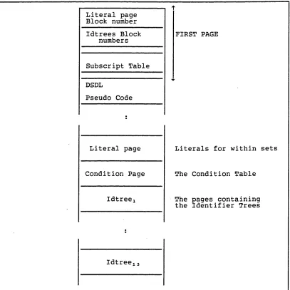
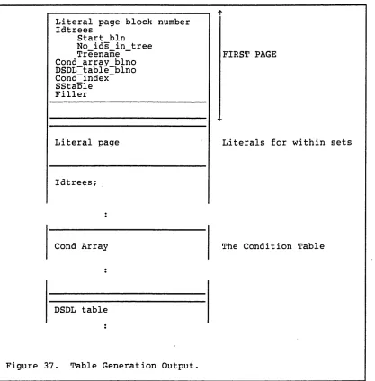
Figure 37. Table Generation Output... 60
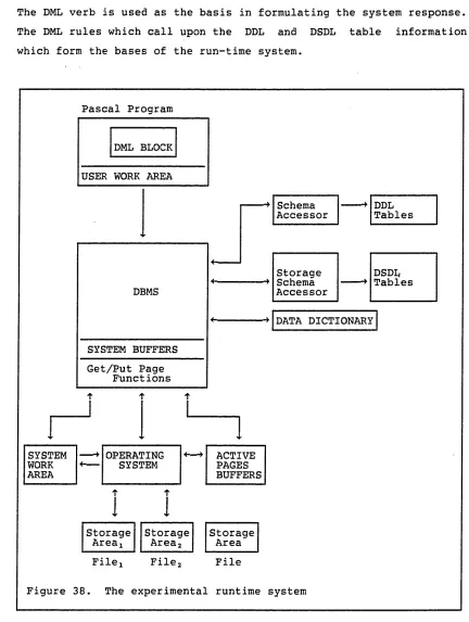
Figure 38. The experimental runtime system ... 63
Figure 39. DML verb STORE block structure interface ... 66
Figure 40. Pascal block structure for DML verb STORE interface 67 Figure 41. The Storage Structures required during Input and Output... 74
Figure 42. Physical Page Format . ... 76
Figure 43. Specification of Prefix Map ... 77
Figure 44. Pointers configurations...81
Figure 45. Insertion into a Set Order is PRIOR, supported by FIRST, NEXT p o i n t e r s ... 82
Figure 46. The reorganisation of storage record Chemical for C h e m - 2 ...92
Figure 47. Data as inserted with Version 1 of the storage example storage schema... 94
CHAPTER 1. INTRODUCTION
The concept of the Conference on Data Systems Languages (CODASYL) was formed during discussions of the Common Business Oriented Language (COBOL) in 1959. By 1965 with the success of COBOL under its belt CODASYL was looking to extend its activities; this they did by creating the List Processing Task Force to develop list processing capabilities for COBOL. Since the term 'list processing' did not fit in with the concept of COBOL, the group renamed themselves the Data Base Task Group (DBTG).
The group's first developments, the Data Description Language (DDL) and the Data Manipulation Language (DML), the schema for data description and the language for host access, were presented in an interim report to the CODASYL Programming Languages Committee in 1969{l6). The revised report{l7) published in 1971 was to form the basis of what is now known as the network database system model and has been fundamental to several commercial implementations.
As a result of the interest stirred by the DBTG report, CODASYL, in late 1971, formed the Data Description Languages Committee (DDLC) whose initial role was to clarify the functionality of the schema DDL. Two years later in 1973 the DDLC published the schema DDL as a Journal of Development{B4}. At this time the Data Base Administration Working Group (DBAWG), a working group of the British Computer Society (BCS), were incorporated under the auspices of the DDLC.
It was thought to be desirable to have the description of the data separate from the description and control of its storage criterion. Therefore the DBAWG initiated modifications to the schema DDL to remove those storage related aspects, which were present. The DBAWG developed these storage constructs into a language for use by the Data Base Administrator (DBA) which was first published as an appendix to the 1978 DDLC Journal of Development Schema DDL {B5}.
the schema, subschema or application programs. The ability to reorganise on a dynamic incremental basis was provided in the 1981 JOD{B6}. It was the aim of the project reported in this thesis to show that this functionality was as feasible as it was desirable.
The development of a compiler/processor for the DSDL was seen as the first aim of the project. Started in 1980 it was hoped to produce two or more variations on the possible implementations of this compiler/processor. The first implementation to produce tables to be stored in some form of 'dictionary', the second as 'assembler' type code with processors to satisfy the DML requests put to the Data Base Management System (DBMS). Using these tables and/or code a simulated run-time system was to be produced to investigate dynamic incremental reorganisation.
There were various stages to the production of the run-time system. The design of the data storage and access methods. The design and implementation of the DBMS, the core of the run-time system. The specification of methods by which dynamic reorganisation could be included. Implementation of these reorganisation facilities, and evaluation of the techniques that were required in the light of reorganisation. Finally to investigate and possibly simulate the effect of reorganisation on the storage structures, system structures and access methods.
Discussions within the DBAWG led to many changes in both the syntax and semantics of the DSDL. These changes were frequently directly related to the correctness of the DSDL definition and as such had to be incorporated in this implementation. This movement in the target and complexity of functionality implied revision of the time scales involved. During the latter stages of the compiler development and the initial DBMS development American National Standards Institue(ANSI) committee X3H2 produced from the 81 CODASYL DDL what has become the Network Data Language (NDL) ANSI standard{B2}. The ANSI version has been adopted by the International Organisation for Standardisation (ISO) as an International Standard Database Language NDL{B20}. The decision was taken by DBAWG to develop the DSDL toward this possible standard. It was felt that the project reported in this thesis could help in this adaptation if the basis was changed to NDL.
However this proved to be an even more mobile target, because of which a fix was taken on the 1983 version of the ANSI-NDL{b1}.
l.l Structure of the Thesis
Chapter 2 gives a brief description of the various types of database model, and their Reorganisation and Restructuring capabilities, with references to past and present implementations. Presented in Chapter 3 is the functionality of the CODASYL Model including a functional description of the DML, DDL/NDL and DBMS. The DSDL is described in Chapter 4 with particular detail paid to the reorganisation capabilities provided.
The example in Chapter 5 presents the development of an application through the design of a schema and storage schema using the DDL, and DSDL, the effect of the NDL changes are considered, together with the
syntactical development of Version 2 of the example.
The Compiler/Table generator is presented in Chapter 6 reflecting on the effect this detailed investigation had on the DSDL.
C
HAP
TER 2. DATABASE ARC
HI
TECTURES
To understand the concept of a 'database' and the term 'dynamic incremental reorganisation' it is necessary to investigate the various types of database model. Each model is presented together with a comparison of their access and storage methods, with particular reference to implementations. The terms restructuring and reorganisation are defined together with their relationships to the models and implementations.
The term database is said to originate in the 1960's in papers concerning defence systems presented at a symposium sponsored by the System Development Corporation{B26}. The initial definition of the term involved files, entries, keys, and data, but has evolved from simply the means of data retrieval into one which involves storage, definition, access and manipulation of data, and referential and integrity constraints. The latter are rarely part of the integral definition and implementation of a database system.
There are three categories of data model: hierarchical, network and relational.
2.1
Hierarchical
The hierarchical model can be seen as a special case of the network model, where the resultant data structure diagram is an ordered tree or simple set (see Figure 1). Such a restricted data structure diagram is referred to as a hierarchical definition tree. The root nodes can be accessed in order of the hierarchical key by scanning or directly, using either an index or by hashing. From each parent a child record may be accessed either sequentially or via a pointer mechanism. The Information Management System (IMS) is an implementation of such a hierarchical system released in 1968 by Rockwell/IBM and provides HSAM, HISAM, HIDAM, and HDAM access
CITY VILLAGE COUNTY
TOWN
COUNTRY
Figure 1. The Hierarchical model
Level 3 Level 1 Level 1
methods{2,6,7,12,14,B35}. Other hierarchical implementations include
BDMS{74) and SYSTEM 2000{l2) which uses inverted files{6}.
2.2 Network
The network data model provides additional relationships over the simple set of the hierarchy: related entity sets, cycles, multi-participating record to set relationships and the ability to represent many to many relationships. The representation of many to many and cyclic relationships was fundamental to the 1981 CODASYL network model (see Figure 2).
In CODASYL terminology a set type is the definition of the relationship and a set is an occurrence of the set type. A record type may participate as a tenant in many set types, but an occurrence may not participate as a member of more than one occurrence of the same set type. Each set may be an empty set. A set type may be owned by the system in which case there is only one set occurrence of that type. A cyclic relationship is one where a record type acts as owner and possibly indirectly a member within the same cycle of sets. In
WARD
DOCTOR P-D
BED PATIENT
t
Figure 2. CODASYL Network - including Many to Many and Cyclic Relationships
the network model these relationships or set types are given names such as DOCTORED BY, where PATIENT DOCTORED BY DOCTOR.
There may be many access paths, and the performance of the database is dependant upon the links maintained. These paths are maintained by the pointer/key system adopted between the owner and member(s) of the sets - where owner and member are particular record types. Detailed expansion of the CODASYL network model follows in Chapter 3.
The predominant disciple of the network model is IDMS {B13,B32,B34}, produced by Cullinane with a second version by International Computers Limited (ICL). The IDMS architecture follows the CODASYL
1971 report of the DBTG. Cullinane has since upgraded it to meet the
1975 CODASYL specification. ICL upgraded their version to include some aspects of the storage schema mentioned in the 1978 appendix to the DDLC JOD, however, it is not known whether this includes any dynamic reorganisation facilities. Indeed the schema still includes area specifications, a storage facility removed from the schema to the storage schema in 1978 as a result of DBAWG representations to
the DDLC. Other CODASYL network type implementations include UNIVAC's DMS1100{B35} (based on the 1969 DBTG report) and BOEING IPAD
{B35}.
2.3 Relational
There are now many books and papers written on the subject of relational DBMS's and models, some theoretical others performance related. It is not possible here to develop the total concept of relational theory merely to give substance to the storage perspectives which will be described later. Nor can all books and papers be referenced, however, some of those which either give an overview of all models or performance between models are referenced, from which references containing explicit details may be found.
The true relational model has the underlying mathematical concept of the set-theoretic relation {B34}, which is a subset of the Cartesian product of a list of domains. A domain is a set of values. The members of a relation are termed a tuple, a tuple may be represented by rows of a table, for example SQL/DS{B17} and ORACLE{B24}. All rows should be distinct on the prime key, however, this is not always adhered to, as in IBM's SQL/DS{B17}.
A relational DBMS is one which supports a relational model and its access language may be based on a relational algebra or the relational calculus. The data represented in the model is access path independent, which is achieved by the process of normalisation. The degree of independence is defined by conformity to one of the levels of normalisation. Codd defined three levels of normalisation, Boyce-Codd Normal Form is now named as a fourth {12,14}. Formal definitions of the four normal forms may be found in {Bll}. Basically a relation is said to have achieved fourth normal form if:
. a. every attribute in a relation is based on a simple domain, i.e.
b. each non-prime attribute is fully dependent upon every key.
c. all transitive dependencies of non-prime attributes on keys is removed.
d. any multi-valued dependencies which are not also functional dependencies are eliminated.
Third normal form which conforms to the first three points is the most usually adopted form. There are said to be degrees of relational systems, conformity of such systems to the relational data model are categorised explicitly by Schmidt and Brodie {B29} on the work of the Relational Task Group (RTG) of the American National Standards Institute (ANSI). Schmidt and Brodie states that a system should not be called "relational" unless it satisfies the following minimum subset of conditions:
a. 'All information in the database is represented as values in tables.
b. There are no user-visible navigation links between these tables. c. The system supports at least the select, project, and equi-join
or natural join operators of the relational algebra - in whatever syntax is found convenient, but without resorting to commands for iteration or recursion, and with the provision that none of these operators is restricted by whatever..access paths have been predefined.'
The result of this investigation of the current system functions was the definition of a language which describes the functionality of a 'tabular relational' database system. This is called SQL after the IBM relational query language SEQUEL (Structured English Query Language) and its developed system SQL/DS (VM/CMS), DB2 (MVS). The language has been produced by the ISO TC97/SC21/WG3 committee as the International Standard, Database Language SQL{B21}.
Of hardware based database systems there appear to be three: IDM 500 (Briton Lee) {B29,12,94,95}; DIRECT (University of Wisconsin) {ll}; and CAFS (Content Addressable File Store) from ICL. The relation language of IDM (IDL) resembles QUEL of INGRES.
It is not clear which was the first relational system, however the Peterlee Relational Test Vehicle (PRTV) {B29,B35,12} was said to have four versions from 1970 - 78, and must surely have been one of the first. 1975 had seen the production of RAPID (origins STATPAK)
{B29,12} and MRDS/LINUS {B29,12}. Amongst the next wave were ORACLE {B29,B34,94,95}; PASCAL/R {B29,12,74}; QBE {B29,B34,B36}; ASTRAL {B29}; MRS {B29,12,94,95}; followed by IDAMS {B29}; IDM {B29,12,94,95}; NOMAD and NOMAD2 {B29,B34}; RAPPORT {B29,12}; and SQL/DS{B17} which was based on SYSTEM R{B29,B32,B34,B35,9,10,12,14,20,67,93,94},
Relational systems use a tuple of a relation like an occurrence of a record or a row of a table, and a primary key value could be seen as the owner of a value based set for equivalent foreign keys. The storage adopted by SQL/DS is not far removed from the CODASYL IDMS logical representation, but without the set pointers, in that it puts individual rows in pages in a dbspace, either sequentially or using an index, where a dbspace is simply a logical collection of logical pages taken from a storage pool of VM minidisks. The access methods used are what it terms a relational scan, or a segment scan in System R{9}, where the entire dbspace is searched for all records of the table, order is immaterial, or via a user defined INDEX, which is a b-tree type implementation stored with the table on the same pages. Access should be, according to relational theory, through the Primary
Key{BIO,B11,B12} however this is not adhered to in SQL/DS where an INDEX can be created on any column or group of columns, uniqueness is not enforced and there can be more than one per table. A simpler implementation by the Science and Engineering Research Council of R-EXEC{66}, based on G-EXEC an earlier implementation at the NERC (1973-1974){40}, uses the one table per file structure and predicate calculus to access tuples from the file, where each file self describes the table structure.
2.4 Rest
ructuring and Reorganisation
schema. For example changing the logical structure of the schema DDL by the addition of a column or the redefinition of a table or record and its set access path mechanisms - in the case of the network or hierarchical models. Obviously the underlying logical to physical mapping is also affected as a consequence of such a restructuring.
The aim of reorganisation, however, is to improve performance by providing hidden mechanisms and storage control to improve the access and storage of the data. As such it should have no impact on the logical structure of the schema or associated application programs.
Conversely a restructure implies changes to be made to the schema, subschemas, application programs and to the storage mapping specifications. Wilson {89} describes some of the problems latent in the restructuring of a CODASYL type database and how neither the structure nor the implementations at the time provided these capabilities. In fact no implementation achieved the full capabilities described by the CODASYL system. It was conceivable that future CODASYL type systems would evolve further restructuring capabilities, however the development of relational systems has reduced the desirability of this functionality because of the necessary complexity of network systems.
Hierarchical and Network based systems such as ICL's IDMS, Cullinane's IDMS and IBM's IMS {89,B13} still require unloading and reloading all or part of the database, to implement restructuring. Restructuring is one of the desirable attributes of a Relational system, where there are none of the restrictions of set relationships between the third normal form relations to be maintained. Systems such as SQL/DS, MRS, NOMAD, PRTV and RAPID all provide the facilities required to restructure. For example in SQL/DS new tables may be created at any time, provided the creator has the necessary permissions, and columns may be added using the SQL command ALTER. Columns may only be added to the end of a stored row/tuple. There are no facilities for changing the implied domain of an attribute.
Reorganisation is the collective term by which none logical changes which improve access and storage of data is termed. There are two distinct types of change. First, strategy reorganisation which is the collective term for those changes used to control the allocation of
record occurrences and set linkages to the storage media space. Secondly, physical placement reorganisation which includes garbage collection of dead space and the re-location of record occurrences to make retrieval more efficient.
Further reorganisation has been more highly developed for network systems. Traditionally any reorganisation that systems provided was statically achieved via the use of unload and reload varying the new storage criterion, strategy 2 as described by Sockut {80,81}, which implies a block on all user access of the data. A variation of strategy 2 is to reorganise in place (strategy 1) which also blocks user read and update.
An alternative is to reorganise the database dynamically with usage, which may be achieved in one of two ways. By a background concurrent utility (strategy 4 of Sockut) which reorganises a finite part of the database allowing access to the rest of the database. Or incrementally as structures are referenced by the system maintaining full user access (strategy 3). The most common functionality provided by systems is garbage collection, many papers on reorganisation {32,79,82,83,92} refer primarily to algorithms and modelling techniques for performance monitoring and improvement of this type of reorganisation.
Factors which differentiate between the types are based on the finiteness of operation, the time of stoppage, locking and journalising requirements and resource usage costs.
Static reorganisation is a clearly defined finite operation it requires application software to be stopped, potentially for long periods, however techniques such as sorting{20} may be used to improve access performance.
Incremental reorganisation runs concurrently with applications, data is reorganised, as necessary, when used, there is no explicit termination point. This causes the most commonly used portion of the database to be reorganised first. As will be shown later this can add a considerable overhead to the application access if not held in check. However the overall cost may be less than a total background reorganisation, in overall resource usage. Not all forms of reorganisation may be incremental, for example new indexes must be created statically.
C
HAP
TER 3. T
H
E CODASYL
MOD
EL
The main reason for choosing the network architecture was the association with and close theoretical knowledge of the DBAWG's network data storage description language, which provided the desired reorganisation facilities. At no time has a commercial system been developed which provides the full range of these database administrator facilities for dynamic incremental reorganisation.
The main elements to the CODASYL architecture are the database management system (DBMS), the associations in the real world described by the schema (DDL) and the storage definition (DSDL) of the entities in the schema.
3.
1 The conceptual f
ramework
A rununit is a user activation of an application program. Using DML statements, the rununit makes a call for data to the Database Management System (DBMS). The DBMS has access to the information necessary to process the request via links to the data description and storage description as can be seen in Figure 3. The DBMS processes the request, obtaining further information from the schema DDL and storage schema DSDL, as required.
Application A Application B Application N
Program a Program b Program n
Application program to Subschema mapping
Subschema A Subschema B
Host Lang + DML Host Lang
+ DML Host Lang+ DML
Subschema to Schema Mapping
Schema DDL t
Schema to Storage Schema Mapping
Storage Schema DSDL
Operating System
Storage
Files
Figure 3. A CODASYL DBMS Architecture
3.2 The Data Manipulation Language (DML)
In commercial systems such as IDMS the Data Manipulation Language (DML) is normally embedded in a host language, such as COBOL. As such it is used to READY the database, or parts thereof, for access via the verbs FIND and GET, FETCH, MODIFY, STORE, and ERASE on records or items and CONNECT, DISCONNECT and RECONNECT on records to sets. The
D B M S
DMCL
data used is then COMMITted back to the database, and exited via the FINISH statement. Access is given to the database error conditions and keys.
A record is selected by the use of the record selection expressions within a FIND or FETCH. The selection expressions are used to find the required record for example the NEXT RECORD IN THE SET. Full details may be found in {B8) and are described in {B11,B23,B32,B15,B22}.
3.3 The Subschema/ Schema DDL
The subschema provides the program application view of the database, which may be the same as the schema view. Conversely it may be a subset of the overall schema view, where the schema view could take account of all data which may be held in the future not just that which is currently required.
The schema DDL is used to describe a logical database, and may be shared by many programs written in many languages. This description is in terms of the names and characteristics of the Data Items, Data Aggregates, Records and Sets included in the database and the relationships that exist and must be maintained between occurrences of those elements in the database.
Sets consist of collections of records one of which may be declared as the owner record type with one or more member record types.
A RECORD is described in terms of data items and data aggregates.
This description is independent of any host language.
A vector is a one dimensional sequence of data items, all with identical characteristics. A repeating group is a collection of data of differing characteristics which occur more than once. The latter facility is provided by the use of the level numbers nested within an occurs clause, the former by the occurs clause on the same level as the item.
A SET is defined by specifying an owner, an ordering method, error and access control routines and member information. A set may be either owned by a record type or the system. A record type may own any number of sets, but an occurrence of a record, may only own one set occurrence of a particular set type. A record occurrence may be a member of only one set occurrence of a set type, but may also be an owner of a different occurrence of the same set type.
The members of a set may be ordered using any of a number of record ordering strategies (eg NEXT, PRIOR) or they can be held in a sorted order{B28}.
Key's in the schema DDL may also be defined for a record type or a set type with participating records ordered by keys.
3.3.1 The Database Language NDL and Associated DML
The Network Database Language (NDL) is the proposed American National Standards Committee (ANSC) Network Database Draft Standard{B2} as devised by the ANSC X3H2 subgroup using the CODASYL 1981 JOD {B5} as their base document. The NDL has since become the basis for an ISO International Standard, IS 8907{B20}.
This is based upon the CODASYL network design but the overall database concepts have changed slightly providing a stricter, more modular approach for the application programmer. This modularisation
may be used to provide an access control tool with a further tool for transaction control.
Prior to its publication, the DBAWG had removed from the base document for the standard , all references to storage and physical device structures and control mechanisms. However the NDL uses the same fundamental concepts, apart from one or two minor constructs, and thus requires underlying logical to physical mapping, either by implementation controls or by using some form of data storage mapping, such as that provided by the DSDL.
3.3.2 The Differences Between DDL and NDL
During the course of conversion of the DDL into the NDL by the ANSI X3H2 Technical Committee on Database, many changes were made. Some 'of the more important differences which affect the production of an NDL related DSDL, rather than one based upon the current CODASYL DSDL, are: schema record keys, conditional data items, source and result, data check clause on items, null, level numbers for records, and set selection. All of which occur in the DDL but are not supported by the NDL, of these only the removal of set selection, schema record key, and level numbers removes any real functionality from the DSDL, although functionality is removed from the schema. The NDL expanded the idea of sets by including the concept of a structural set.
The removal of the schema key phrase for a schema record means that the DSDL can no longer directly provide indexes which support next and prior searches on the record type. (A duplicates restriction
could also be placed on a record type for this key). However a similar result can be achieved for the record type, if it is a single member type in a system owned automatic set, with sorted order on the same key. A further limitation is that unique keys cannot be enforced.
The removal* of the level numbers implies that all the items are now on the same level, removing the data aggregate and repeating group facility from the schema. Thus enforcing some similarity in data modelling techniques to the normalisation process for relational data systems. For example, the following description of the schema record
Tetra, for the entity TETRAHEDRON, can be represented in the DDL by one record Tetral see Figure 4.
'RECORD Tetral
01 Weight FLOAT 6,2 01 Sides OCCURS 4 TIMES
02 Colour CHARACTER 10 02 Length FLOAT 6,2 02 Angle-Elev FLOAT 5,2
Figure 4. DDL Tetrahedron schema description.
In the NDL this can be represented in one of two ways either by a set type and two record types or one large description. The former description is given in Figure 5 by the set Atetra and the record types Tetra2 and Side.
RECORD Tetra2
ITEM Weight FLOAT 6,2 RECORD Side
ITEM Colour CHARACTER 10 ITEM Length FLOAT 6,2 ITEM Angle-Elev FLOAT 5,2 SET Atetra
OWNER Tetra ORDER FIRST
MEMBER Side
INSERTION MANUAL RETENTION FIXED
Figure 5. NDL(1) Tetrahedron schema description.
The latter description is given in Figure 6 as the large and cumbersome record type Tetra3.
RECORD Tetra3
ITEM Weight FLOAT 6,2 ITEM Si-Colour CHARACTER 10 ITEM Sl-Length FLOAT 6,2 ITEM Sl-Angle-Elev FLOAT 5,2 ITEM S2-Colour CHARACTER 10 ITEM S2-Length FLOAT 6,2 ITEM S2-Angle-Elev FLOAT 5,2 ITEM S3-Colour CHARACTER 10 ITEM S3-Length FLOAT 6,2 ITEM S3-Angle-Elev FLOAT 5,2 ITEM S4-Colour CHARACTER 10 ITEM S4-Length FLOAT 6,2 ITEM S4-Angle-Elev FLOAT 5,2
Figure 6. NDL(2) Tetrahedron schema description.
C
HAP
TER 4. T
H
E DATA STORAGE DESCRIPTION LANGUAGE (DSDL)
In general terms the CODASYL Data Storage Description Language (DSDL) defines how data described in a schema may be organised in terms of an operating system and device independent storage environment. As specified by the DBAWG charter, the DSDL is merely a tool for the Database Administrator and was designed to affect the performance of an application program but not to alter its results. There is, however, no direct relationship between the data contained in the database and the storage schema declarations except that the contents of a record may affect the storage representation.
This chapter provides an historical and conceptual account of the CODASYL DSDL and its subsequent associations with the ANSI NDL.
The DBAWG was set up jointly by the British Computer Society (BCS) and the CODASYL Data Description Language Committee(DDLC). The historical overview outlines the course of events from 1971 to the present day; however it must be noted that the major thrust of this project took account only of these changes that occurred pre-1983.
The major concepts of the DSDL are then described with reference to the syntactical description of the DSDL which is presented in the form of syntax graphs in Appendix E. The concepts are enhanced by reference to non-dynamic objectives by functional categorisation, followed by detailed discussions on records, sets and indexes. The effect of the NDL on this functional specification is then described.
To dynamically tune the database the facilities of reorganisation, as described in Chapter 2 are required, these aids are described with reference to type and occurrence descriptions.
The chapter is concluded by a discussion on the effect of the NDL on these reorganisation concepts.
4.1 Historical overview
Two conferences were held by the British Computer Society in 1970 and 1971, the former to discuss the 1969 CODASYL Database Task Group (DBTG) report the latter their 1971 report. As a result of these conferences several working groups were established by the BCS Advanced Programming Specialist Group. The forerunner of the DBAWG
investigated "Implementations of the CODASYL DBTG proposals".
Developing these proposals further the group contacted and made presentations to the CODASYL DDLC and Data Base Language Task Group (DBLTG). By 1973 the group had turned its attention to the facilities that must be provided by an implementer but were not as yet covered. Thus the group became the "Development of the CODASYL data base proposals". In September of that year the group presented a paper entitled "Facilities for use by the Database Administrator" to the DDLC. Later that year the CODASYL DDLC approved the charter{l8}:
"The DBAWG will develop tools for the use of the database administrator to control the efficient and reliable use of the database."
for the Data Base Administration Task Group and asked the working group to become its nucleus. Wishing to preserve their ties with BCS the group called itself the BCS/CODASYL DDLC Data Base Administration Working Group (DBAWG).
In June 1975 the DBAWG produced a discursive account{4} on storage mapping, integrity control, statistics, restructuring and reorganisation. At this time any references to these constructs were explicitly defined in the CODASYL Data Description Language (DDL).
The aim was therefore to remove all references to such storage structures from the DDL.
These structures formed the base definitions of the Device Media Control Language(DMCL). Which was later renamed the Data Storage Description Language and published as an appendix to the DDL in
a. The logical description of the data storage comprising the linkages and structures required to support the schema, provided by the DSDL, and
b. the actual device area mappings and physical descriptions.
The DMCL provides the mapping between the DSDL descriptions and the actual physical devices. The DMCL as a concept seen in the 1971
report of the DBTG{17} is still required in conjunction with the DSDL, however it may be embedded in the database operating system.
The DSDL was first published in 1978 and provided mapping and fragmentation only, no reorganisation capabilities were presented.
Further enhancements were undertaken to both the DDL and DSDL and these were published in 1981.
Some of the facilities included in the 1981 DDL were: conditional expressions, checks for owner and member records, Boolean and conditional data items. Arithmetic expressions had been added but not published. Those features which had been removed but encompassed within the 1981 DSDL are: areas, measurement, picture clause, structural, tuning from functional and language categories. Also added to the 1981 DSDL was the concept of reorganisation. Altered but unpublished is the reformed set entry syntax which eradicates the conflict between the OWNER and MEMBER clauses. This error was discovered during the course of this project (see Appendix E.2,F,H).
In 1985 with the demise of the CODASYL DDLC the group dropped the term CODASYL from its name. Work progresses not only on storage schemas, but also Access Control, Distributed Databases {45}, and moving towards the relational arena acting as a primary source of
British comment on the ISO SQL. Storage schemas for a relational system are also under investigation.
4.2 Static Functionality of the DSDL
The storage schema is divided syntactically into the entries of storage schema, areas, mappings, storage records, sets and indexes as shown by the syntax graphs in Appendix E. The ordering given to these entries is shown diagramatically in Appendix E.2.
Entries for mapping, storage records and sets are subdivided into sub-entries and then all are subdivided into clauses see Appendix E.2 and Appendix F. Functionally the storage schema can be said to be divided into mapping, storage structures, representation, placement and resource allocation categories. Some of these categories are described further through their association with records, sets and indexes.
4.2.1 Functional and Syntactical Description
The main functions of a storage schema are to control the mapping of records to storage structure representations, to control placement and resource allocation of the structures, and maintain the links supporting access mechanisms. The five entries and the functionality they provide are described briefly.
The storage schema entry merely defines the link to the schema and the version of the storage schema. (See 4.4).
MAPPING FOR Lens IF Macro=true THEN
STORAGE RECORDS ARE L-Model/Description,Macro
ELSE
STORAGE RECORDS ARE L-Model,Whole-desc
Figure 7. 1:N Conditional Mapping of schema record Lens.
The storage area entry identifies and defines the characteristics of a storage area within the database. The size of this area is defined both by the number and size of a page and whether the area is expandable. Any type of entity may be defined as placed within an area.
The storage record entry defines a storage record type, its contents and the placement criteria of any occurrence of that type.
A set entry specifies how storage records are to be connected to support a schema set.
An index entry names and specifies the name and type of an index and its placement within a storage area. The details of storage records, sets and indexes are now described further.
4.2.2 Entity-relationship support within the DSDL
Entities and relationships are supported in the DSDL by storage records, sets and indexes.
4.2.2.1 Storage Record organisation
A storage record is the logical representation of the physical description of all or a part of a schema record. Only those records which map the whole of a schema record which are said to be mapped
1:1, may be seen to be directly accessible from the schema, however an intelligent DBMS could identify when a subschema record maps
through to a storage record and therefore only return that storage record not the whole of the schema record.
A storage record is defined in terms of the data items, its links to other storage records (within a partitioned mapping), its placement criteria, of, and in the, storage record, and the effects of
reorganisation on and of it.
Data items may be explicitly or implicitly represented in a storage record, all items in a schema record may be represented implicitly or explicitly in at least one implicit or explicit supporting record.
The position of a data item is controlled through alignment and the format controls its representation.
Link pointers are those pointers between storage records participating in the same multi-mapping. Link pointers are defined by the LINK clause of the STORAGE RECORD clause. These pointers may be direct or indirect, when there is a storage key index for the record pointed to then that pointer is indirect, for details see 4.2.3. These pointers must provide a closed circuit, that is from any storage record within a multi-mapping it must be possible through one or more other storage records to reach any other storage record of that mapping.
An example of such a link mechanism can be seen by the following description of the storage records L-model, Description, Macro and Whole-desc. The mapping of schema record Lens is multi-conditional to L-model, Description and Macro or L-model and Whole-desc (see Figure 7)
STORAGE RECORD L Model
LINK TO DescrTption, Macro IS DIRECT LINK TO Whole desc IS INDIRECT
STORAGE RECORD Description LINK TO L-Model
STORAGE RECORD Macro LINK TO L-Model
STORAGE RECORD Whole-desc LINK TO L-Model
The implication of the INDIRECT on Whole-desc is that Whole-desc will have an index which is used as its storage key index.
Placement of the data items within a record is ordered as within the storage record definition and specified, justified and aligned depending on the clauses of the data subentry.
A storage record may be assigned to an area and optionally page tuned by means of gross placement and fine tuning. The particular strategy of placement may be chosen to be dependent on values within the schema record, this is controlled by the surrounding IF (condition) THEN placement of the Placement Subentry. For example:
STORAGE RECORD Description LINK TO L-Model
IF Type='ZOOM' THEN
DENSITY IS 2 STORAGE RECORDS PER PAGE PLACEMENT IS SEQUENTIAL ASCENDING Upper WITHIN Equipment FROM PAGE 1000 THRU 6000 ELSE
DENSITY IS 6 STORAGE RECORDS PER PAGE PLACEMENT IS SEQUENTIAL ASCENDING Lower WITHIN Equipment FROM PAGE 1 THRU 999 Figure 9. Conditional placement of Description.
Placement is calculated subject to the fine and gross placement criteria subject to the density specifications. However if the fine adjustments, specified by CALC, CLUSTERED or SEQUENTIAL cannot be adhered to then placement is subject to the gross placement criteria of the WITHIN clause. This can occur when there is insufficient space on the page where the record should have been placed.
CALC placement as specified by the CALC clause is calculated from a defined or implied routine, for dispersion randomly about the page range of the WITHIN clause, if specified. This method provides for the fastest retrieval of ad hoc queries provided all parameters of the function are known.
storage record will, if possible, be placed on the same page as another of the same type representing its closest position in the set order. Otherwise placement is implementer defined. An ad hoc find on a clustered record could be very expensive if no occurrence is known.
SEQUENTIAL placement specified within a storage record description (Figure 9) ensures that within the specified page range subject to the density specifications any record of that type must be stored in such a way that the system may retrieve those records in the manner specified by the ascending/descending key sequence. This storage method need not be physical but may be kept logically by the system.
To retrieve such a record may or may not prove to be expensive.
In fragmenting a record to allow optimal retrieval, the benefits must be weighed against the cost required to recombine such a record, taking into account the efficiency of any optimiser.
4.2.2.2 Sets
Relationships are defined in the schema by sets, which must be supported by the storage schema. The means to support the order and content of a set occurrence is defined in a storage set definition by means of pointers, indexes or identifier values.
Two types of sets may be defined: value based or pointer based sets. Value based sets are connected only at request time, pointer based sets are connected by a combination of logical or physical pointers and indexes.
LAST
FIRST
OWNER OWNER OWNER
NEXT NEXT NEXT
PRIOR PRIOR PRIOR
MEMBER
MEMBER MEMBER
OWNER
Figure 10. Pointer formations of a logical set occurrence
To support the order of a set occurrence as specified in the schema DDL (see Chapter 3) at least the minimal set of pointers and indexes must be defined. One such minimal set for a non-singular set is an index pointed to by the owner which supports every member record type and owner pointers for each member (Figure 11)
OWNER
h-INDEX
Member
k x
Member A. MemberBx
Figure 11. A minimum pointer combination set
The combinations of pointers must be used carefully when supporting the order of a set, it is possible to provide support which will be detrimental to the speed of retrieval. For example a set is completely linked when each member has a prior pointer and the owner has a last pointer. However if it is used to support a set whose order is ascending on a key then to find the first member of the set and follow its sequence requires a highly intelligent system to perform efficiently. In Figure 12 we see that having found the owner
the first record may only be found after passing through the entire chain. It should be remembered also that this simple pass is further complicated by fragmenting the schema records into storage records and the linking provided between them, an expansion of these problems is provided in Chapter 9.
LAST
PRIOR MKEY=aaaEMBER PRIOR
OWNER
MEMBER
KEY=bac PRIOR MKEY=bccEMBER
Figure 12. An Ordered by Key Set occurrence
4.2.3 Indexes
There are two types of schema key: those specified to support a schema record and those to support the order within a set occurrence, both types are supported in the storage schema by indexes.
There are three types of indexes; storage key, record key and set indexes.
Storage key indexes are used to support indirect addressing. A storage key points directly to the storage record it is defined as supporting, this index supports only one storage record type. Any storage record linked indirectly to this storage record will not be affected should the record be moved.
Record key indexes support schema record keys or keyed access to schema records using any combination of schema data items, which may imply some order. The latter two providing extra functionality for system record retrieval to that provided by the schema.
The specification of the USED clause given in Figure 13 is correct according to the syntax and semantics of the DSDL. As the set Manufactures is sorted so all the rules defined in the storage schema (including updates up to December 1980) are adhered to, however after recent debate with the members of the DBAWG it was difficult to see whether the format in the figure is correct or desirable.
USED FOR SET Manufactures MEMBER Camera
KEY Model MEMBER Lens
MEMBER Film KEY
Figure 13. An alternative USED clause to that in Version 1 of the Photographic Storage Schema.
The stored representation of an index is implementer defined however an index is considered to be a sequence of key/pointer pairs or pointers only if no key is involved.
4.3 NDL conformation of the DSDL with the functional changes
As stated in Chapter 3 historically the NDL has as its base the CODASYL DDL, consequently the DBAWG felt it necessary to provide a DSDL which could support a schema defined in NDL. 3.3.2 discussed the changes that were made to produce the NDL, these changes are now discussed as to their affect on the DSDL, and consequently the changes to the DSDL that were necessary.
Facilities which were removed included: schema record keys, set selection and level numbers. The structural set was the main addition.
Schema record keys were supported by the SCHEMA KEY option of the RECORD option of the USED clause. These keys provided a direct link between record access and the indexes of the storage schema, any link between records and indexes for records must now be calculated by an optimiser.
Set selection of the schema provided logical access routes which had to be maintained by the DBMS. The cascade effect of this automatic search and selection had a definite effect on reorganisation, this will be described later in 4.5.
The use of level numbers in the DATA subentry of STORAGE RECORD, enabled the DBA to specify a part of a hierarchy/repeating group with or without specifying individual data items, now the specification of DATA ALL is only at the whole storage record and therefore whole schema record level.
The initial removal of the structural constraint concept by the DDLC caused the value based option for a storage set to have a tenuous place in the storage schema. The rewrite of the syntax rules of SET for value based sets was not resolved. The replacement of insertion by structural set in the NDL provided an excellent hook for value based sets. The main syntax rule specified that value based could only be used if each MEMBER clause of the set type
a. as a structural specification and
b. has a retention clause for specifying FIXED or MANDATORY.
It is not necessary to have a structural set supported by a value based rather than a pointer based structure.
4.4
The DSDL Reo
rganisation
Facilities
'Reorganisation' is the ability to alter the physical structure or access support mechanisms of the database. These changes have already been categorised in Chapter 2 into two types of reorganisation; Strategic and Physical Placement and the methods by which these changes are performed were described as STATIC, DYNAMIC BACKGROUND and DYNAMIC INCREMENTAL reorganisations.
reorganisation as circumstances dictate. The separation into logical and physical description by schema and storage schema provides the necessary environment for both static and dynamic reorganisation to be performed without affecting the logical structure or application programmes.
The DSDL uses what are termed 'versions' of a storage schema to enable a system to provide reorganisation. A DSDL has a syntactical construct called a VERSION clause. A reorganisable object when initially defined is given a version number which is equivalent to the current version number of the storage schema via a VERSION clause. The current version of a storage schema contains all versions of the object definitions, and the new changed definitions. An object's definition may not change between versions unless it is given the new version number. A version of an object may not be omitted from a storage schema unless all previous definitions are omitted and there are no objects currently stored using that version. However, areas must be statically changed as they do not have versions.
With this version control the DSDL provides the following types of strategic reorganisation.
a. Changes to the mapping of record types on to storage areas, including fragmentation, distribution and data item storage specifications.
b. Changes to the mapping of set types on to storage areas including, access through the storage structure of a set type and the ORDER and SORTED clause storage structures.
c. Changes to the mapping of record occurrences and indexes onto storage areas including, record and index occurrence placement.
d. Changes to the placement of objects relevant to each other.
The DSDL does not provide the means by which garbage collection and index compaction may be controlled.