5
IV
April 2017
Technology (IJRASET)
A Semi-Autonomous Security System for Coal
Mine using Wireless Control Based on Real Time
Operating System [RTO]
Mr. J. Jijin Godwoin1, Ms. Sinthiyasruthi. G2, Ms. Nila. S3, Ms. Thilagavathi. T4 1
Asst. Professor, 2,3,4UG Student, Department of Electronics and Communication Yelammal Institute of Technology
Abstract: Novel coal mine management system to solve the real time monitoring and high efficient rescue problems of underground work platforms. Here a robot is designed to detect the obstacles and transfer the information to the base station in order to avoid humane causalities. The robot is equipped with special wheel which is controlled by H-bridge module, allowing it to move in all the possible directions. Also, the robot is enhanced with special range sensor which is used to detect and locate the position of obstacles. In addition to this, gas alert, accident help request, video streaming and voice announcements are provided to the system with a wireless ZigBee which gets the real time values from fire, temperature and tilt sensors. Video camera will transmit the image in Motion-JPEG format along with the speaker which will allows to send emergency commands with the voice message tool. The application firmware works on the top of RTOS [Real Time Operating System] to handle multitasking requirements of the system. This technique has a practical benefit reducing the number of causalities with least buffering time. Keywords: Sensor; H-bridge Real time monitoring; Wireless ZigBee
I. INTRODUCTION
The most basic forward abundant fossil fuel that is available in this world is coal. It serves as a raw material in various industries such as metallurgic and chemical industries. Among all the countries in the world China has occupied the top three positions for its proven reserves of coal. Due to the enormous availability of coal, China still exists as one of the biggest consumer and producer of coal, accounting for about 70% of the country’s total consumption of energy. Even though the development in the underground mining security monitoring system is being upgraded year by year, it is an eventual truth that if the appropriate technology is applied with perfect advancement, this accident can be effectively prevented. All these researches that has been carried out in this area has given a high decline in the fatality rate [about 24%] during the accidents from 2012-2013 in China [1-2].
In India eleven workers died and over 50 others were feared trapped when an open-cast coal mine at PahariaBhodaye in Jharkhand’s Godda district collapsed on 30 December 2016.There has been significant decrease in the rate of fatality in India such as from1975-80 it was 185, but with2011-12 its just 55.This has been made possible with the help of laws that has been incorporated with the safety of the workers, but even this rate can be brought to null by cooperating the advancement InTechnology with the available technological resources.
In current scenario there are security systems with autonomous wireless technology which will allow us to perform the basic monitoring functions [3]. The dynamic data on environmental condition and other situation is transferred using the ZigBee technology which is been directed to the base station and viewed with high accuracy [2]. The automation feature of this system will enhance its feasibility as it does not need any human interface. The environmental monitoring consists of a suite of different sensors to capture the local environmental condition. This system will be helpful in preventing the actual accident by giving an appropriate warning and help request in real time.
II. DESCRIPTION
A. Processor Unit
Technology (IJRASET)
[image:3.612.195.431.122.443.2]Watchdog Timer, System Tick Timer, Power-On Reset, Power Management Unit, Crystal oscillator, 12MHz internal RC oscillator, PLL, JTAG and Serial Wire Debug/Trace Port with ETM, Up to 42 General purpose I/O pins. Processor unit of LPC1313 is shown in figure 1.
Figure 1. Processor unit
B. Sensor Unit
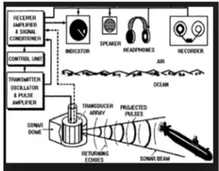
1) Sonar: Sonar (initially an acronym for sound navigation and ranging) is a procedure that utilizes sound engendering (typically submerged, as in submarine route) to explore, speak with or distinguish objects on or under the surface of the water, for example, different vessels. Two sorts of innovation share the name "sonar", passive sonar is basically tuning in for the sound made by vessels; active sonar is radiating beats of sounds and tuning in for echoes. Sonar might be utilized as a method for acoustic area and of estimation of the resound attributes of "focuses" in the water. Acoustic area in air was utilized before the presentation of radar. Sonar may likewise be utilized as a part of air for robot route, and SODAR (an upward looking in-air sonar) is utilized for environmental examinations. The term sonar is likewise utilized for the hardware which is used to produce and get the sound. Wave transmission and reception in the SONAR is shown in Figure 2
[image:3.612.229.387.581.704.2]Technology (IJRASET)
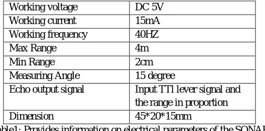
2) Electric Parameter:
Working voltage DC 5V Working current 15mA Working frequency 40HZ
Max Range 4m
Min Range 2cm
Measuring Angle 15 degree
Echo output signal Input TTl lever signal and the range in proportion Dimension 45*20*15mm
Table1: Provides information on electrical parameters of the SONAR
HC - SR04 provides 2cm - 400cm non-contact measurement function, the ranging accuracy can reach to 3mm. The modules includes ultrasonic transmitters, receiver and control circuit. The basic principle of work:
Using IO trigger for at least 10µs high level signal
The Module automatically sends 840 kHz and detect whether there is a pulse signal coming back.
If the signal is back, through high level, time of high output IO duration is the time from sending ultrasonic to returning. The HC-SRO4 SONAR module is been shown in the below figure3.
3) Equation:
[image:4.612.177.441.89.220.2]= (ℎ ℎ ∗ 340 )/2
Figure 3. HC-SRO4
C. Fire Sensor
A flame detector is a sensor intended to distinguish and react to the nearness of a flame or fire. Reactions to a recognized fire rely on the establishment and installation, however can incorporate sounding an alert, deactivating a fuel line, (for example, a propane or a characteristic gas line), and enacting a fire concealment framework. When the fire sensors are being utilized as a part of modern devices, for example, modern heaters, their part is to give affirmation that the heater is legitimately lit; in these cases they take no direct action beyond notifying the operator or control system. A fire locator can regularly react faster and more precisely than a smoke or heat detector because of the systems it uses to distinguish the fire.
Features: Allows the robot to detect flame from 2m away, Fire indicator LED, Calibration preset for range adjustment.
1) Specification:
Parameter Value
Operating voltage +5V
Range 2m
[image:4.612.190.425.389.471.2]Technology (IJRASET)
2) Pin Details:
a) Connect ground and VCC pin to +5v and GND.
b) Connect OUT pin to port pin of controller for interfacing with applications.
[image:5.612.202.427.198.352.2]The fire sensor circuit is excessively delicate and can distinguish an ascent in temperature in its region. The fire sensor module comprises of IR sensor, comparator and LED. It has got three pins GND, VCC and OUT. At particular point where fire is identified by IR sensor LED glows, and OUT pin is set high. The OUT pin can be given as contribution to the microcontroller and can be utilized for any fire recognition applications. Whenever the LED is ON it shows that fire is identified. For instance you can interface it to a bell by means of microcontroller and when OUT pin of flame sensor module is set high. A fire sensor module is shown in figure 5.
Figure 5. Flame detection sensor module
D. Gas Sensor
A gas detector is a device that detects the presence of gases in an area, often as part of a safety system. This sort of hardware is utilized to identify a gas spill or different outflows and can interface with a control framework so a procedure can be naturally closed down. A gas detector can sound an alarm to administrators in the area where the leak is occurring, giving them the opportunity to leave. This type of device is important because there are many gases that can be harmful to organic life, such as humans or animals. Also, the change in resistance is used to calculate the gas concentration. Semiconductor sensors are commonly used to detect hydrogen, oxygen, alcohol vapor, and harmful gases such as carbon monoxide. Figure 6 shows the MO2 gas sensor module.
Figure 6. MQ2 Gas sensor
1) Features:
a) Wide detecting scope
b) Fast response and high sensitivity
c) Stable and long life
d) Simple drive circuit
Technology (IJRASET)
symbol Parameter Name
Technical condition
Remar ks VC Circuit
Voltage
5V±0.1 AC OR DC VH Heating
Voltage
5V±0.1 AC OR DC
RL Load
Resistance
Can Adjust RH Heater
Resistance
33Ω ±5% Room
Temperature PH Heating
Consumption
[image:6.612.148.464.299.450.2]Less than 800mw
Table 3: Electrical parameters of the MQ2 gas sensor.
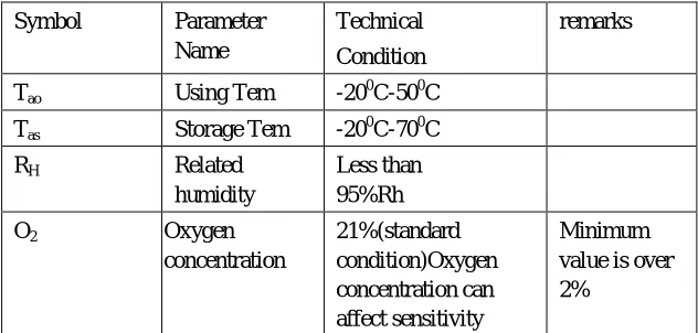
3) Environmental Condition:
Symbol Parameter Name
Technical Condition
remarks
Tao Using Tem -200C-500C Tas Storage Tem -200C-700C RH Related
humidity
Less than 95%Rh O2 Oxygen
concentration 21%(standard condition)Oxygen concentration can affect sensitivity Minimum value is over 2%
Table 4: Technical conditions for the identification of different gasses
4) Sensitivity Characteristics:
Symbol Parameter name Technical Parameter Remarks RS Sensing Resistance 3KΩ -30KΩ
(1000ppm isobutene)
Detecting
Concentration scope: 200ppm-5000ppm LPG and propane A
(3000/1000) Isobutene
Concentration Slope
rate ≤0.6
300ppm-5000ppm butane 5000ppm-20000ppm methane Standard Detecting condition
Temp: 200C ±20c Humidity: 65%±5%
VC: 5V±0.1 Vh: 5V±0.1
300ppm-5000ppm H2
Preheat Time Over 24 hour 100ppm-2000ppm
[image:6.612.50.550.484.707.2]Technology (IJRASET)
Resistance value of MQ-2 is difference to various kinds and various concentration gases. So, when using these components, sensitivity adjustment is very necessary. We recommend that you calibrate the detector for 1000ppm liquefied petroleum gas<LPG>, or 1000ppm iso-butane<i-C4H10>concentration in air and use value of Load resistance that (RL) about 20 KΩ (5KΩ to
47 KΩ). When accurately measuring, the proper alarm point for the gas detector should be determined after considering the
temperature and humidity influence.
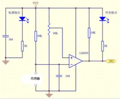
E. Tilt Sensor
[image:7.612.223.398.239.339.2]A tilt sensor can measure the tilting in often two axes ofa reference plane in two axes. In contrast a full motion would use at least three axes and often additional sensors. One way to measure tilt angle with reference to the earth’s ground plane, is to use an accelerometer. The functionality of tilt sensors is impacted by factors such as gravity, vibration, temperature, zero offset, linearity, cross-axis sensitivity, acceleration /deceleration, stock, clear line of sight between the client and the deliberate point, and calibrations of tilt sensors. Figure 7 shows the module of tilt sensor.
Figure 7. Tilt sensor
On-board LM393 is a voltage comparator chip and photo activity sensing probe. This chip support 5V/3.3V voltage input. Output of the effective signal is low lever, at the same time indicator light is off, Output signal can directly connect with the microcontroller IO, The sensitivity of the signal detection can be adjusted, Reserve a line voltage to compare circuit (P3 has been leaded out), PCB size: 30(mm) x15(mm).figure 8 shows the systematic block diagram of the following sensor which consist of an op-amp LM393.
1) Systemic Diagram:
Figure 8. Circuit connection
F. Wheeled Navigation Robot
Wheeled robots are robots that navigate around the ground using motorized wheels to propel them. This design is simpler than using treads or legs and by using wheels they are easier to design. Wheeled robots use differential steering, which uses separately driven wheels for movement. They can change direction by rotating each wheel at a different speed. There may be additional wheels that are not driven by a motor these extra wheels help keep it balanced.
[image:7.612.199.394.429.591.2]Technology (IJRASET)
traction on the wheels.
G. Video Camera
Cameras for industrial and medical applications are usually lightweight, compact, robust and versatile. Moreover, they provide High-quality videos. They are sold with their own optics. , the onboard microcontroller captures the JPEG images from the camera using the built-in DCMI peripheral and starts to stream it over the web in Motion-JPEG format, a widely used video streaming format, at an acceptable rate between 10 and 15fps. The image resolution is fixed at either 470 x 272 or 640 x 480. The microcontroller has a large RAM memory area, about 256KB, which is a must for this kind of application.
Unfortunately, most part of them (GoPro, Sony AS100VR, Contour, Midland xlc, Drift HD Ghost, ION Air Pro, etc.) are provided with fish- eye lenses or very large FOV (> 170), inducing a too big distortion, that can only be removed with post-processing. On the other hand, industrial cameras are too bulky and heavy to be mounted on a helmet. Furthermore, a battery powered wearable embedded system must be small and light enough, because it needs to be carried by the personnel. The use of LEDs lights are important for supervision and vision cameras. The low lighting conditions give a large percentage of blurry images. At the same time high luminance of light cannot be accepted because most of the elements in the environment are reflective. So, proper adjustment of luminance is also important.
Figure 9.Video clipping of the coal mine facility.
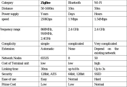
1) Zigbee Technology : The ZigBee protocol is the only international IEEE 802.15.4 standard wireless sensor network protocol in existence, catering to the specific needs of low-power, low maintenance monitoring and control systems with talks of using it in sensor network [4]. The name refers to the waggle dance of honeybees after their return to the beehive [5]. The network layer supports three topologies: star, cluster tree and mesh. Direct sequence spread-spectrum at 2.4 GHz (ISM), 915MHz (the United States) and 868MHz (Europe) is applied in industrial, scientific and medical frequency band [4]. Figure 10 shows the ZigBee hardware module.
[image:8.612.205.386.555.703.2]2) Zigbee Module
Technology (IJRASET)
Comparative Analysis Of Different Techniques Providing Similar Services
Category ZigBee Bluetooth Wi-Fi
Distance 50-1600m 10m 50m
Power supply Years Days Hours
speed 250Kbps 1 Mbps 1.54Mbps
Frequency range 868MHz, 916MHz, 2.4GHz
2.4 GHz 2.4 GHz
Complicity simple complicated Very complicated Extension Automatic None Depend on the
existing network
Network Nodes 65535 8 50
Cost of Terminal unit low low high Linking time 30ms up to10s Up to 3s Security 128bit, AES 64bit, 128bit SSID
Ease of use Easy Normal Hard
Prime Cost Low Low Normal
Table6: Comparative analysis of three wireless networking options such as ZigBee, Bluetooth and Wi-Fi.
H. Software Used
1) LPCXpresso: LPCXpresso is a new, low-cost development platform available from NXP. The software consists of an enhanced, Eclipse-based IDE, a GNU C compiler, linker, libraries, and an enhanced GDB debugger. The hardware consists of the LPCXpresso development board which has an LPC-Link debug interface and an NXP LPC ARM-based microcontroller target. LPCXpresso is an end-to-end solution enabling embedded engineers to develop their applications from initial evaluation to final production.
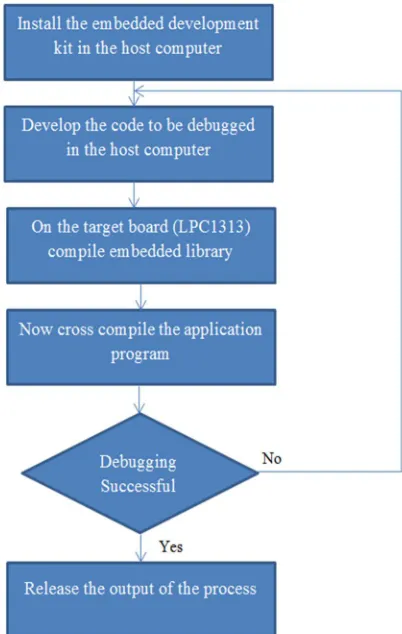
III. SOFTWARE DESIGN
Here the lower level computer hardware is built on kernel of arm microprocessor as the core. The application software for the users is developed using Win CE embedded operating system. After this the security monitoring software platform is being developed as per the flow chart addressed below in the Figure 15. The coding process is carried out using the software Atollice true studio, which is then exported to the flash magic software to view the output.
[image:9.612.104.509.90.368.2]IV. LAYOUT OF ZIGBEE MODULE IN UNDERGROUND SHAFT MINE
Technology (IJRASET)
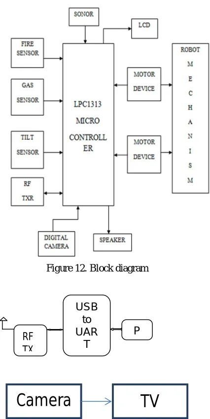
[image:10.612.204.417.91.515.2]V. DESIGN AND PROPOSAL OF THE SYSTEM
Figure 12. Block diagram
Figure 13: Shows the video camera connection with the micro-controller. VI. FRAMEWORK OF THE SYSTEM
Various sensors like carbon monoxide MQ7, temperaturesensorLM-35, and water level detector are being used to calculate the dangerous threshold levels of the environmental data. analog measurement from local site of various parameter such as carbon monoxide, increasing temperature, different water level and through ADC give digital output to the microcontroller LPC 1313 . The communication of the sensing board and the processor are possible with the UART to TCP facility in the processing unit. ZigBee transmits this digital sensor data to the remote monitoring site located at maximum distance from local site (100m). ZigBee can be used inside mines as router. Whenever the sensor data exceeds the specified threshold (preset) value of temperature, carbon monoxide and water level, the ZigBee module at remote monitoring site is transmit alert signal to local site by blowing buzzer continuously.
This data transmitted, once exceeding the threshold value will be reported as dangerous and are being reported to the base monitoring system between 0-100ms time limit. This acknowledgement when dangerous will be reported to the workers via the voice message facility that has been provided in the system. Thus on hearing those message the works will try and evacuate the area or the help will be provide simultaneously. In additional to this feature there is a live relay of video capture through series of JPEG image form which is possible with RTOS multitasking facility.
Camera
RF rx
TV
USB to UAR
T RF
TX
Technology (IJRASET)
[image:11.612.226.386.156.330.2]The conventional mine security framework can be adequately replaced by the surveillance and wellbeing framework. The framework is solid, steadfast, continuous, prudent and easy to use. A bigger range and more profundity inside risky underground mines are presently can be secured and mischance’s can be controlled viably. The framework joined the low power; minimal effort ZigBee based high recurrence remote information transmission innovation. The sensor and ZigBee module can be ideally introduced in mines (routers). Proper observing and correspondence is conceivable between the representatives and the checking site which can take fitting activities all the more quickly and astutely.
Figure 14. Experimental setup.
[image:11.612.207.408.365.682.2]Technology (IJRASET)
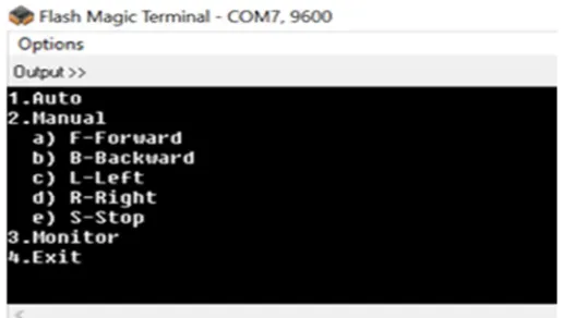
VII. OUTPUT
[image:12.612.170.438.169.721.2] [image:12.612.177.435.173.319.2]Output commands in which the robot is operated is shown in the Figure 15. There are three modes of operation-AUTO, MANUAL, MONITOR. In auto mode the robot detects the obstacles automatically and sends the commands to the base station as well as to the miners by using speaker facility. Auto mode is shown in the figure 16. In manual mode the user can control the robot manually by passing the commands [Forward, Backward, Left, Right, and Stop] which is described in Figure 17. In monitor mode the values of X, Y, Z axis [due to vibration], distance of the obstacles, temperature is displayed through which constant monitoring can be done. Monitoring mode is shown in the figure 18.
Figure 15. Commands in the output screen
Figure 16. Auto mode
Technology (IJRASET)
Figure 18. Monitoring mode
VII. CONCLUSION
The coal mine security monitoring and management system designed in this paper is to combine ZigBee and robot mechanism. It has the functions of sensing the fire, vibration, ultrasonic, gas and provides communication to the base station. The system is more reliable even in extreme environmental situations. The embedded solution ensures that the workers are safe enough to work under ground by providing continuous monitoring with least buffering time.
REFERENCES
[1] Zhang Xiaodong1,2, Tan Yuegang1, Hou Yan2, “Research and application of Embedded technology in remote network monitoring system of coal mine”, 2014 26th Chinese Control and Decision Conference (CCDC).
[2] Ye Yalin, Zhang Lin,SongXiaofeng, Xin Dan, Huang He, “A novel coal mine security monitoring system based on ZigBee”, 2015 International Conference on Intelligent Transportation, Big Data & Smart City.
[3] Md. FasiulAlamSerafeimKatsikasStathesHadjiefthymiades, “An advanced system architecture for the maintenance work in extreme environment”, 2016 International Conference.
[4] IEEE paper on “ZigBee based intelligent helmet for coal miners” by Cheng Qiang, sun ji_ping, zhangzhe, zhangFebruary [2009] CSIE2009.653.
[5] “Wireless Networking through ZigBee Technology” by P. Rohitha, P.Ranjeet Kumar, Prof. N. Adinarayana, Prof.T.VenkatNarayanaRaoISSN: 2277 128X vol.2 [7 July 2012].
[6] Xuan-min Lu, Shu-yuan-shao, “A Novel platform of coal mine monitoring system based on wireless sensor network”, 2010 Information and Automation (ICIA).
[7] Liang Zhang, Xiao sheng, Dianguo XU, “A novel security monitoring system of coal mine based on power line communication dynamic routing technology”, 2014 Industry Applications Society annual meeting.
[8] Zhuang wei, Mu longhuua,”CPS based relay protection system for underground coalmine distribution networks”, 2010 Power system Technology(POWERCON).
[9] Ma Xiang-Min, Wen Chen.”Optimization of PID parameters for coal gas monitored control system based on artificial immune algorithm”, 2011 Computer science and Automation engineering (CSAE).