Design of a Compact Planar Antenna for Ultra-wideband Operation
M. N. Shakib
1,2,4, M. Moghavvemi
1,2,3, and W. N. L. Mahadi
1,41
Department of Electrical Engineering 2
Center for Research in Applied Electronics (CRAE), Faculty of Engineering 4
Electromagnetic Radiation & Devices Research (EMRD), Faculty of Engineering University of Malaya, Kuala Lumpur, 50603, Malaysia
engmdns@yahoo.com, mahmoud@um.edu.my, wnliza@um.edu.my
3
Engineering Department
University of Science & Culture, Tehran, Iran
Abstract ─ In this paper, a new compact planar antenna is proposed for UWB (Ultra-wideband) operations. The proposed antenna has a low profile structure, consisting of a radiating patch, notched ground plane, and a novel arc-shaped strip connected between the microstrip feed line and the radiating patch. By using the proposed structure, broadband antenna with good impedance matching is obtained. Measured results show that the antenna can achieve a bandwidth of 96.22%. The proposed antenna is optimized in order to satisfy the required band with a good radiation pattern. The fabricated antenna has a compact size of 16u 20u1.6 mm3. These features demonstrate that the proposed antenna is a suitable candidate for UWB applications, due to its simple configuration, compactness, and low fabrication costs.
Index Terms ─Broadband antenna, planar antenna, ultra-wideband antenna.
I. INTRODUCTION
Ultra-wideband system has been widely used for the last few years due to its amazing frequency spectrum in wireless communication. According to the Federal Communications Commission (FCC), UWB system is defined as any radio system operating in the band of 3.1-10.6 GHz, has a 10 dB bandwidth larger than 25% percent of the center frequency and a maximum equivalent isotropic radiated power spectral density of -41.3 dBm/MHz [1-3]. In applications such as wireless personal area networks, low data rate
communication and low power consumption with location and tracking, UWB technology became a favorable candidate in wireless system [4-7]. It is a known fact that UWB antenna is one of the promising key parts in a UWB system [8]. Also, any antenna implemented in a UWB system plays a more unique role than it does in conventional narrowband systems. However, antenna design for UWB applications faces many challenges.
Planar antennas present appealing physical features, such as low profile, small in size, conformability, easy to integrate with other devices and low cost. Owing to these attractive characteristics, planar antennas have gained the attention for use in UWB operations, especially in the Body Area Network (BAN) for medical applications [9-13]. However, the size optimization in the UWB frequency band remains a challenge for antenna designers.
Various structures have been studied to achieve ultra-wideband antennas [14-16] in practical applications, such as the waveguide horn [17], log periodic [18], planar inverted cone [19], and biconical [20]. A new bi-arm rolled monopole antenna with small characteristics for UWB has been investigated in [21]. In [22], planar ultra-wideband (UWB) dipoles used by elliptical elements are introduced. Again, small sized UWB antennas printed with quasi transmission lines and band dispensation are presented in [23-25]. However, these designs require large grounding area or a large radiator. In addition, antennas with circular, square, elliptical, pentagonal shapes are
1054-4887 © 2015 ACES Submitted On: July 30, 2013
proposed in [26-29] for UWB applications. However, the ground planes of these structures are perpendicular to the radiator, which leads difficulty to use for integration with PCB technology.
Recently, a double sided microstrip antenna using modified ground plane is investigated [30-32]. In [31], the antenna comprises of a rectangular patch with an inverted L-shaped slits, cut out in the ground to control the antenna’s resonant frequency and bandwidth. Although these antennas can cover the UWB band, it cost more with a larger antenna size. In this paper, a new compact planar antenna with arc-shaped strip, connected to microstirp feed line and radiating patch is introduced for UWB applications. The proposed antenna is smaller and more compact compared to the designs reported in [30-32].
[image:2.612.355.499.300.442.2]II. ANTENNA DESIGN
Figure 1 shows the layout of the proposed planar antenna. The antenna is fed by a microstrip line and printed on an FR4 substrate with a thickness of 1.6 mm and a permittivity of 4.4. The width of the microstrip feed line is fixed at 2.8 mm. The proposed antenna consists of a notched radiating patch, feed line, a ground plane, and a new arc-shaped strip. The patch is connected to the feed line with a width and length of WxandLx, respectively. In this design, a new arc-shaped strip, connected from the microstrip feed line to the radiating patch is proposed. This extended arc-shaped protruded strip acts as an impedance matching element to control the impedance bandwidth of the proposed antenna by creating additional surfaces of current paths in the antenna. Therefore, the excited current shifts its upper resonances, so much so that a wider impedance bandwidth can be produced, especially at upper band. Further more, the ground plane comprises of a rectangular slit that is almost centered under the feed-line, which creates an extra resonance, leading to the improvement in the bandwidth. The introduction of a notch on the left corner of the radiating patch reduces the size of patch and helps to acquire better matching at lower frequency band. There is a gap that is equal to s between the radiating element at the top layer and the ground plane at the bottom layer. Parametric analysis concerning the choice of the optimum value of s indicated that it should not be larger than the
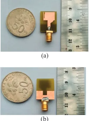
[image:2.612.352.502.480.682.2]thickness of the substrate h, in order to get the wider operation bandwidth. The photograph of the antenna is shown in Fig. 2, which has a surface area of 20u16 mm2. The proposed antenna is significantly smaller by 51.5%, 87.2%, and 46.7% compared to the recently designed antennas reported in [30], [31] and [32], respectively. A 50 Ω SMA connector is connected to the end of the feeding strip and grounded to the edge of the ground plane. The proposed antenna is analyzed by the electromagnetic simulator HFSS, based on finite element method. The optimized values of the proposed antenna design parameters are as follows: L=20 mm, W=16 mm, Lx=8 mm, Wx=11 mm, Lx1=6 mm, Lg=8 mm, Wf=2.8 mm, Ws=3.7 mm, Ls=4 mm, s=0.3 mm, Larc=2.7 mm, h=1.6 mm, Lx2=2 mm, and Wx1=0.5 mm.
Fig. 1. Geometry of the proposed antenna.
Fig. 2. Photo of the proposed antenna: (a) top layer, and (b) bottom layer.
Lg
Top layer L
Wf
s
900 Larc
Bottom layer W
Wx
Lx L
x1
Ws Ls
x y
z
thickness, h
Lx2
Wx1
(a)
III. RESULTS AND DISCUSSIONS
The microstrip antenna has been constructed and optimized to exhibit the effect of the bandwidth enhancement technique. Figure 3 shows the simulated reflection coefficient of the optimized proposed antenna and proposed antenna without an arc-strip, notched in radiator and ground plane slit.Fig. 3. Simulated reflection coefficient: (a) proposed antenna, and (b) proposed antenna without arc strip and ground slit.
As shown in the figure, firstly, the proposed antenna was configured with a compact microstrip fed rectangular patch, with a partial ground plane on the bottom layer to provide the fundamental and next higher resonances at 5.6 GHz and 8.6 GHz, respectively. Then, a newly proposed arc-shape strip is integrated with the design that produces higher current flow at higher frequencies. This results in the fundamental frequency shifting to 7.2 GHz, and next higher resonant frequency shifts to 9.7 GHz, resulting in a wider frequency band from 4.8 to 11.7 GHz. This technique implies that the arc-strip plays an important role in the broadband characteristics and in determining the sensitivity of impedance matching. A small rectangular slit of 4 mm by 3 mm is inserted into the ground plane as reported in [7], to obtain better matching on the frequency band. The integration of this technique causes the upper resonance of the designed antenna to shift from 9.7 GHz to 12.1 GHz, and a new resonance is introduced at 13.1 GHz, leading to the achievement of higher frequency band to up to 14.5 .GHz.
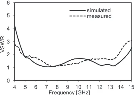
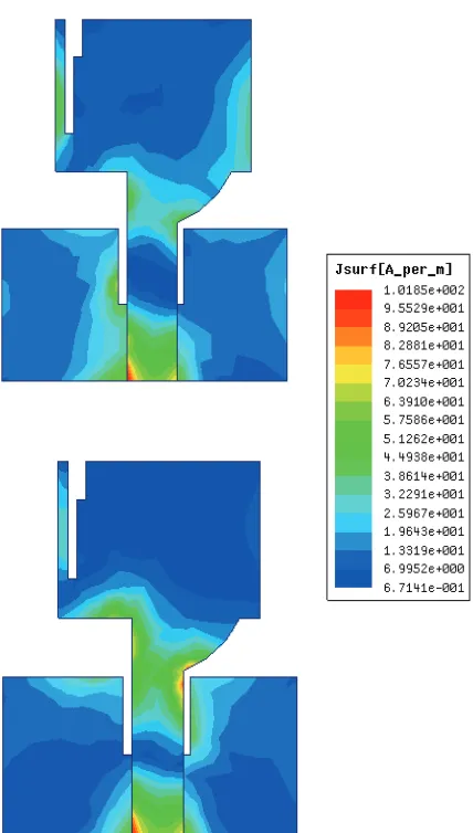
Figure 4 shows the simulated and measured VSWR of the proposed antenna. The proposed antenna is measured with a Rohde & Schwarz ZVA24 vector network analyzer. The simulated bandwidth covers from 4.8 GHz to 14.5 GHz, while the measured bandwidth covers from 4.8 GHz to 13.7 GHz. The discrepancies between the simulated and measured results may be attributed to the connector, which is not taken into account in the simulation. Figure 5 shows the current distribution at 6 GHz and 9 GHz. At 6 GHz, it can be observed that most of the electric currents are distributed on the bottom edge of the feeding strip, the junction of the rectangular radiator, and the left side of the notched ground plane. Again, at 9 GHz, the majority of the electric current is concentrated around the arc-shaped strip and the bottom edge of the radiator. This suggests that the arc-shaped strip has a significant effect on the antenna performance at higher operating frequencies.
[image:3.612.322.541.518.674.2]To measure and identify S21 and group delay values, a distance of 50 cm between the two equal (Tx/Rx) antennas was chosen. Figure 6 shows the measured values of S21 in the face-to-face scenarios. Figure 7 indicates group delay on the antennas. The measured group delay is almost flat, at about 2ns, while the variation is about 0.48ns. This small variation in group delay signifies a good linear transmission function characteristics of the proposed antenna for UWB applications. Figure 8 shows the variation of the simulated and measured peak gain of the antenna. It is observed that the proposed antenna has a gain above 2.56 dBi in the entire operating band.
Fig. 4. Simulated and measured VSWR of proposed antenna.
-45 -40 -35 -30 -25 -20 -15 -10 -5 0
4 5 6 7 8 9 10 11 12 13 14 15
|S
11
| (dB)
Frequency [GHz]
proposed ant.
proposed ant. w/o arc-strip, ract. notch and ground slit
0 1 2 3 4 5 6
4 5 6 7 8 9 10 11 12 13 14 15
VSW
R
Frequency [GHz]
Fig. 5. Current distribution of the proposed antenna at: (a) 6 GHz, and (b) 9 GHz.
[image:4.612.320.538.69.232.2]Fig. 6. Measured S21 (magnitude) of the proposed antenna.
[image:4.612.322.538.287.444.2]Fig. 7. Measured group delay of the proposed antenna.
Fig. 8. Simulated and measured gain of the proposed antenna.
Figure 9 illustrates the simulated and measured radiation patterns, including the co-polarization and cross-co-polarization in the E-plane (xz-plane) and H-plane (yz-plane) at 6 GHz. It can be seen that the radiation patterns in xz- and yz-plane are quasi omni-directional at 6 GHz.
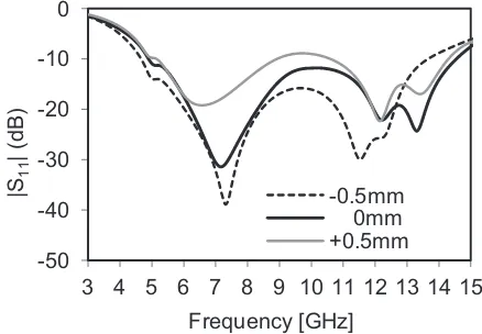
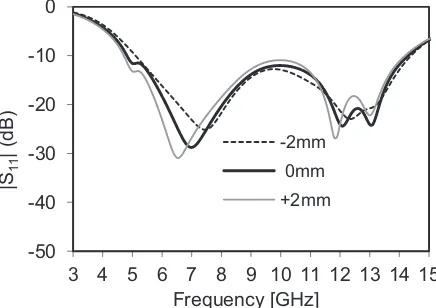
A parameter study has been performed to observe the effect on the antenna performances on the impedance matching, due to changes in the s parameter. As shown in Fig. 10, increasing or decreasing the s parameter experiences better matching at the lower frequency band, but at the expense of reducing the upper edge frequency, resulting in a reduction in the bandwidth. Hence, s=0.3 mm was chosen as the control model. In Fig. 11, with decreasing Larc, a mismatch on the -80
-70 -60 -50 -40 -30
4 5 6 7 8 9 10 11 12 13 14 15 16
Magnitude (dB
)
Frequency [GHz]
1 1.5 2 2.5 3
4 5 6 7 8 9 10 11 12 13 14 15 16
Group delay
(ns)
Frequency [GHz]
0 1 2 3 4 5 6
4 5 6 7 8 9 10 11 12
Gai
n
(dBi)
Frequency [GHz]
[image:4.612.79.297.502.660.2]antenna leads to small bandwidth drop on the upper frequency. With increasing Larc, the lower and upper resonances shift upward which causes band reduction on the antenna. Hence, Larc=2.7 mm was chosen as control model.
[image:5.612.86.240.153.466.2]Fig. 9. Simulated and measured radiation pattern of the antenna at 6 GHz: (a) xz-plane, and (b) yz-plane.
[image:5.612.77.296.530.682.2]Fig. 10. Effects on reflection coefficient with changing s parameter.
Fig. 11. Effects on reflection coefficient with changing Larc parameter.
In Fig. 12, with increasing or decreasing Ls, a mismatch is occurred on the entire band, leads to a bandwidth reduction on the antenna. At Fig. 13, with decreasing Lg, a mismatch is occurred in the frequency. But, the operating bandwidth remains the same. With increasing Lg, the resonances shift upwards, causing bandwidth fall on the antenna. Hence, Lg=8 mm was chosen as control model.
In Fig. 14, with increasing Ws, the lower frequency shifts upward, leads to a bandwidth drop on the antenna. With decreasing Ws, a mismatch occurs in the frequency, but the operating band remains the same. Hence, Ws=3.7 mm was chosen as control model. In Fig. 15, with changing L, the designed structure performs good matching on the antenna. In Fig. 16, with increasing W, a good matching is observed. But, with decreasing W, the upper resonant shifts upward, causing a bandwidth drop on the upper frequency. Hence, W=16 mm was chosen as control model.
Fig. 12. Effects on reflection coefficient with changing Ls parameter.
-60 -50 -40 -30 -20 -10 0
0 30
60
90
120
150 180 210 240 270
300 330
-60 -50 -40 -30 -20 -10 0
0 30
60
90
120
150 180 210 240 270
300 330
-50 -40 -30 -20 -10 0
3 4 5 6 7 8 9 10 11 12 13 14 15
|S
11
| (
dB)
Frequency [GHz] -0.5mm 0mm +0.5mm
-50 -40 -30 -20 -10 0
3 4 5 6 7 8 9 10 11 12 13 14 15
|S
[image:5.612.323.535.542.681.2]11
| (dB)
Frequency [GHz]
-0.5mm 0mm +0.5mm
-50 -40 -30 -20 -10 0 10
3 4 5 6 7 8 9 10 11 12 13 14 15
|S
11
| (dB)
Frequency [GHz]
-2mm 0mm +2mm
Simulated Co-polar
Measured Co-polar
Simulated Cross-polar
Measured Cross-polar (a)
Fig. 13. Effects on reflection coefficient with changing Lgparameter.
Fig. 14. Effects on reflection coefficient with changing Wsparameter.
[image:6.612.75.297.285.437.2]Fig. 15. Effects on reflection coefficient with changing Lparameter.
Fig. 16. Effects on reflection coefficient with changing Wparameter.
IV. CONCLUSION
In this paper, a new compact planar UWB antenna has been presented and analyzed in detail. By successfully utilizing the arc-shaped strip structure, radiating plate, notched ground plane and adjusting the parameters, the antenna has obtained a wide bandwidth with quasi omni-directional radiation pattern. Despite exhibiting wide impedance bandwidth, the antenna has achieved compact and low profile characteristics. The prototype has been fabricated and measured. The results have shown a good agreement between simulations and measurements. Therefore, these characteristics have made the proposed antenna a suitable candidate for UWB applications.
ACKNOWLEDGMENT
The authors would like to thank the support of the Bright Spark Grant (No: BSP/APP/1133/2012) and PPP Grant (No: PG131-2013A) of the University of Malaya.
REFERENCES
[1] X. H. Wu and A. A. Kishk, “Study of an ultra-wideband omnidirectional rolled monopole antenna
with trapezoidal cuts,” IEEE Trans. Antennas
Propagat., vol. 56, no. 1, pp. 259-263, Jan. 2008.
[2] Y. S. Li, W. Li, and W. Yu, “A multi-band/UWB MIMO/diversity antenna with an enhanced isolation using radial stub loaded resonator,” Applied Computational Electromagnetics Society
(ACES) Journal, vol. 28, no. 1, pp. 8-20, Jan. 2013.
[3] M. N. Shakib, M. T. Islam, and N. Misran, -50
-40 -30 -20 -10 0
3 4 5 6 7 8 9 10 11 12 13 14 15
|S
11
| (dB)
Frequency [GHz]
-1mm 0mm +1mm
-50 -40 -30 -20 -10 0
3 4 5 6 7 8 9 10 11 12 13 14 15 16
|S
11
| (dB)
Frequency [Ghz]
-1mm 0mm +1mm
-50 -40 -30 -20 -10 0
3 4 5 6 7 8 9 10 11 12 13 14 15
|S
11
| (dB)
Frequency [GHz]
-2mm
0mm
+2mm
-50 -40 -30 -20 -10 0
3 4 5 6 7 8 9 10 11 12 13 14 15
|S
11
| (dB)
Frequency [GHz]
[image:6.612.76.294.496.650.2]“Stacked patch antenna with folded patch feed for
ultra-wideband application,” IET Microw.
Antennas Propag., vol. 4, no. 10, pp. 1456-1461,
2010.
[4] H. B. Li and R. Kohno, “Introduction of SG-BAN in IEEE 802.15 with related discussion,” Proc.
2007 IEEE Int. Conf. Ultra-Wideband, Singapore,
pp. 134-139, Sept. 2007.
[5] R. Kohno, K. Hamaguchi, H. B. Li, and K.
Takizawa, “R&D and standardization of body area
network (BAN) for medical healthcare,” Proc.
2008 IEEE Int. Conf. Ultra-Wideband, Hannover,
pp. 5-8, Sept. 2008.
[6] L. Huang, P. Harpe, C. Zhou, S. Rampu, M. Vidojkovic, G. Dolmans, H. Groot, and K.
Imamura, “Performance evaluation of an ultra-low
power receiver for body area networks (BAN),”
Proc. 2010 IEEE 21st Int. Symp. Personal, Indoor
Mobile Radio Commun. Workshops, Istanbul, pp.
89-94, Sept. 2010.
[7] J. Jung, W. Choi, and J. Choi, “A small wideband
microstrip-fed monopole antenna,” IEEE Microw.
Compon. Lett., vol. 15, no. 10, pp. 703-705, Oct.
2005.
[8] K. S. Ryu and A. A. Kishk, “Ultra-wide band
dielectric resonator antenna with broadside patterns mounted on a vertical ground plane edge,” IEEE
Trans. Antennas and Propagat., vol. 58, no. 4, pp
1047-1053, Apr. 2010.
[9] M. Mighani, M. Akbari, and N. Felegari, “A novel
SWB small rhombic microstrip antenna with parasitic rectangle into slot of the feed line,” Applied Computational Electromagnetics Society
(ACES) Journal, vol. 27, no. 1, pp. 74-79, Jan.
2012.
[10] M. Mighani, M. Akbari, and N. Felegari, “A CPW
dual band notched UWB antenna,” Applied
Computational Electromagnetics Society (ACES)
Journal, vol. 27, no. 4, pp. 352-359, Apr. 2012.
[11] M. N. Jahromi and N. K. Barchloui, “Analysis of
the behavior of Sierpinski carpet monopole
antenna,” Applied Computational Electromagnetics
Society (ACES) Journal, vol. 24, no. 1, pp. 32-36,
Feb. 2009.
[12] M. Mehranpour, J. Nourinia, C. Ghobadi, and M.
Ojaroudi, “Dual band-notched square monopole
antenna for ultra-wideband applications,” IEEE
Antennas Wireless and Propag. Lett., vol. 11, pp.
172-175, 2012.
[13] N. Ojaroudi, M. Ojaroudi, and S. Amiri,
“Enhanced bandwidth of small square monopole
antenna by using inverted U-shaped slot and conductor-backed plane,” Applied Computational
Electromagnetics Society (ACES) Journal, vol. 27,
no. 8, pp. 685-690, Aug. 2012.
[14] H. Schantz, “A brief history of UWB antennas,”
Proc. Ultra Wideband Systems and Technologies,
pp. 209-213, Nov. 2003.
[15] Z. Zhang and J. T. Bernhard, “A circular wire antenna for ultra wideband applications,” Proc. IEEE Int. Symp. Microwave, Antenna, Propagation, and EMC Technologies for Wireless
Communications, 2007, Hangzhou, pp. 496-499,
Aug. 2007.
[16] N. Behdad and K. Sarabandi, “A compact antenna
for ultrawide-band applications,” IEEE Trans.
Antenna Propag., vol. 53, no. 7, pp. 2185-2192,
2005.
[17] C. H. G. Henrique, M. M. Afonso, R. S. Alfpio, U. C. Resende, M. A. O. Schroeder, and L. A. L. Santos, “Approximated raising of the curvature of a double-ridged waveguide horn in a computational model,”IEEE MTT-S Int. Conf., pp. 435-438, Oct. 2007.
[18] G. Engargiola, W. Holzapfel, and A. Lee, “Planar
channelized log-periodic antenna,” IEEE Int.
Symp., pp. 306-309, Aug. 2005.
[19] S. Y. Suh, W. L. Stutzman, and W. A. Davis, “A new ultra-wideband printed monopole antenna: the planar inverted cone antenna (PICA),”IEEE Trans.
Antennas Propagat., vol. 54, no. 5, pp. 1361-1365,
May 2004.
[20] H. Ghannoum, S. Bories, C. Roblin, and A. Sibille,
“Biconical antennas for intrinsic characterization of
the UWB channel,” IEEE Int. Workshop Antenna
Technology, pp. 101-104, Mar. 2005.
[21] Z. N. Chen, “Novel bi-arm rolled monopole for
UWB applications,” IEEE Trans. Antennas
Propagat., vol. 53, no. 2, pp. 672-677, Feb. 2005.
[22] H. G. Schantz, “Planar elliptical element ultra
-wideband dipole antennas,” in Proc. 2002 IEEE
AP-S Int. Symp., San Antonio, TX, USA, pp.
44-47, Jun. 2002.
[23] C. W. Ling and S. J. Chung, “A simple printed
ultra-wideband antenna with a quasi-transmission
line section,” IEEE Trans. Antennas Propagat.,
vol. 57, no. 10, pp. 3333-3336, Oct. 2009.
[24] K. G. Thomas and M. Sreenivasan, “A simple
ultra-wideband planar rectangular printed antenna
with band dispensation,” IEEE Trans. Antennas
Propagat., vol. 58, no. 1, pp. 27-34, Jan. 2010.
[25] Z. N. Chen, T. S. P. See, and X. Qing, “Small
printed ultra-wideband antenna with reduced
ground plane effect,” IEEE Trans. Antennas
Propagat., vol. 55, no. 2, pp. 383-388, Feb. 2007.
[26] M. J. Ammann and Z. N. Chen, “Wideband
monopole antennas for multiband wireless
systems,” IEEE Antennas and Propagation
Magazine, vol. 45, no. 2, pp. 146-150, Apr. 2003.
Wide-band planar monopole antennas,” IEEE Trans
Antennas Propagat., vol. 46, no. 2, pp. 294-295,
Feb. 1998.
[28] E. Antonino-Daviu, M. Cabedo-Fabre’s, M.
Ferrando-Bataller, and A. Valero-Nogueira,
“Wideband double-fed planar monopole antennas,”
Electron. Lett., vol. 39, no. 23, pp. 1635-1636,
Nov. 2003.
[29] Z. N. Chen, M. Y. W. Chia, M.Y.W. and M. J.
Ammann, “Optimization and comparison of
broadband monopoles,” IEE Proc. Microw.
Antennas Propag., vol. 150, no. 6, pp. 429-435,
Feb. 2003.
[30] R. Azim, M. T. Islam, and N. Misran, “Ground modified double-sided printed compact UWB antenna,” Electron. Lett., vol. 47, no. 1, pp. 9-11, Jan. 2011.
[31] M. M. Azer, S. I. Shams, and A. M. M. A. Allam,
“Compact double-sided printed omni-directional
ultra wideband antenna,” Int. Symp. on Antenna
Technology and Applied Electromagnetics and the
American Electromagnetics Conf., Toronto, ON,
pp. 1-4, Jul. 2010.
[32] M. Koohestani and M. Golpour, “Very ultra
wideband printed CPW-fed slot antenna,”Electron. Lett., vol. 45, no. 21, pp. 1066-1067, Oct. 2009.
Mohammed Nazmus Shakib
received his B.Sc. degree in Engineering from Multimedia University, Malaysia, the M.Sc. degree from National University of Malaysia, Malaysia. He was a Research Assistant at National University of Malaysia from 2008 to 2010. He is a Faculty Member in the Department of Electronics and Communication Engineering, Manarat International University at Bangladesh since 2011. Currently, he is pursuing the Ph.D. at The University of Malaya, Malaysia under the Bright Spark Program. He has published many international conferences and
journals. He is also a Reviewer of a few journals such as IET, PIER, JEMWA, etc. His research interests mainly include RF, measurement antennas, patch antennas, implantable antennas and UWB technology.
Mahmoud Moghavvemi
graduated from The State University of New York (SUNY) at Buffalo with a B.Sc. (CIE) and B.Sc. (Electrical Engineering). He obtained his M.S. degree from Bridgeport University and later on a Ph.D. from The University of Malaya. He is currently attached to the Department of Electrical Engineering, University of Malaya. Besides teaching duties, he is actively involved in various research projects and has published more than 200 articles in peer reviewed technical journals and conferences. He is the Founder and Director of The University of Malaya Center for Research in Applied Electronics (CRAE).
Wan Nor Liza Mahadi graduated