©IJRASET: All Rights are Reserved
222
Design and Construction of a Conventional
Elevator
S.K Bello1, N.A Badiru2
1
Department of Mechanical Engineering, Lagos State Polytechnic, Ikorodu, Lagos, Nigeria.
Abstract - This paper is about the design and construction of an elevator. Elevator is a device that efficiently moves people or goods vertically between floors of a building, vessel, or other structures. They are generally powered by electric motors that either drive traction cables or counterweight systems like a hoist, or pump hydraulic fluid, to raise a cylindrical piston in the form of a jack. During the industrial era, the development of elevators was led by the need for movement of raw materials including coal and lumber from the hillsides. The technology developed by these industries and the introduction of steel beam construction worked together to provide the passengers freight elevators in use today. The construction and installation of other systems of elevator in existence are quite expensive compared to the conventional system. This research work was aimed at developing an elevator that does not use the hydraulic system but more to the conventional system in order to save cost in construction, installation and maintenance.
Keywords- Elevators, Pneumatic, Pulley, Hydraulic, Commutator, Counterweight
I. INTRODUCTION
Elevators of nowadays are constructed using hydraulic and other complex systems. What we try to establish in this paper is to develop an elevator that does not use the hydraulic system but more to the conventional system. The system that will be used in the course of this paper is the pulley system to lift the car. The reason for this includes the following: The systems of other elevator are complex and difficult to maintain; cost of maintaining an elevator is high and takes time to maintain; the construction and installation of other system of elevators are quite expensive compared to the conventional system (Moore and Niall, 2000). Skyscrapers are symbols of technological development, employed the services of elevators the movement of people from one floor to another without which the construction of skyscrapers could have been rendered useless. Consequently the purpose of this paper is to design and construct a convectional elevator. The materials used in the fabrication are steel bar, hollow bar, pulley, rope, wheel, and bearing. The first reference to an elevator is in the works of the Roman architect Vitruvius. In some literary sources of later historical periods, elevators were mentioned as cabs on a hemp rope and powered by hand or by animals. In the middle 1800's, there were many types of crude elevators that carried freight, most of them ran hydraulically. The first hydraulic elevators used a plunger below the car to raise or lower the elevator. A pump applied water pressure to a plunger, or steel column, inside a vertical cylinder. Increasing the pressure allowed the elevator to descend. The elevator also used a system of counter-balancing so that the plunger did not have to lift the entire weight of the elevator and its load. The plunger, however, was not practical for tall buildings, because it required a pit as deep below the building as the building was tall. Later a rope-geared elevator with multiple pulleys was developed. In 1852, Elisha Otis introduced the safety elevator, which prevented the fall of the cab if the cable broke. The design of the Otis safety elevator is somewhat similar to one type still used today. On March 23, 1857 the first Otis passenger elevator was installed at 488 Broadway in New York City. An elevator shaft was included in the design for Cooper Union, because Cooper was confident that a safe passenger elevator would soon be invented. The shaft was cylindrical because Cooper felt it was the most efficient design. The first electric elevator was built by Werner von Siemens in 1880. The development of elevators was led by the need for movement of raw materials including coal and lumber from hillsides. The technology developed by these industries and the introduction of steel beam construction worked together to provide the passenger and freight elevators in use today. Elevators are classified based on their hoist mechanism; elevators can be rope dependent or rope-free. There are at least three means of moving an elevator; traction elevator, hydraulic elevator and climbing elevator.
©IJRASET: All Rights are Reserved
223
which is attached to a gearbox driven by a high-speed motor. Gearless traction machines are low-speed, high-torque electric motors powered either by AC or DC. In this case, the drive sheave is directly attached to the end of the motor. A brake is mounted between the motor and drive sheave to hold the elevator stationary at a floor as shown in Fig.1.
©IJRASET: All Rights are Reserved
224
Fig 1: Traction Elevator Fig 2: Hydraulic Elevator
Fig 3: Pneumatic Elevator
Pneumatic Elevators: Pneumatic elevators are raised and lowered by controlling air pressure in a chamber in which the elevator sits. By simple principles of physics; the difference in air pressure above and beneath the vacuum elevator cab literally transports cab by air as can be seen in Fig.3. It is the vacuum pumps or turbines that pull cab up to the next floor and the slow release of air pressure that floats cab down.
©IJRASET: All Rights are Reserved
225
Fig 4: The load F on the moving pulley is balanced by the tension in two parts of the rope supporting the pulley.
Elevator Safety: An elevator cab is typically borne by six or eight hoist cables, each of which is capable on its own of supporting the full load of the elevator plus twenty-five percent more weight. In addition, there is a device which detects whether the elevator is descending faster than its maximum designed speed; if this happens; the device causes copper brake shoes to clamp down along the vertical rails in the shaft, stopping the elevator quickly, this device is called the governor (Kopetz, 2011). In addition, a hydraulic buffer is installed at the bottom of the shaft to somewhat cushion any impact.
II. METHODOLOGY
A. Components Parts of the Elevator
The elevator consists of the following key parts:
One or more cars (metal boxes) that rise up and down. Counterweights that balance the cars.
An electric motor that hoists the cars up and down, including a braking system. A system of strong metal cables and pulleys running between the cars and the motors
B. Description of Elevator’s Parts
The elevator consists of the following key parts: One or more cars (metal boxes) that rise up and down; Counterweights that balance the cars; An electric motor that hoists the cars up and down, including a braking system; A system of strong metal cables and pulleys running between the cars and the motors.
1) Counterweight: In practice, elevators work in a slightly different way from simple hoists. The elevator car is balanced by a heavy counterweight that weighs roughly the same amount as the car when it's loaded half-full. When the elevator goes up, the counterweight goes down—and vice-versa, which helps in four ways: The counterweight makes it easier for the motor to raise and lower the car; the counterweight reduces the amount of energy the motor needs to use; the counterweight reduces the amount of braking the elevator needs to use. The counterweight makes it much easier to control the elevator car.
©IJRASET: All Rights are Reserved
226
there's the coil, mounted on an axle that spins around at high speed—and this is called the rotor. The rotor also includes the commutator.
Fig.5 A simplified diagram of an electric motor.
3) Brakes: The most common elevator brake is made up of a compressive spring assembly, brake shoes with linings, and a solenoid assembly. When the solenoid is not energized, the spring forces the brake shoes to grip the brake drum and induce a braking torque. In order to improve the stopping ability, a material with a high coefficient of friction is used within the breaks, such as zinc bonded asbestos. Typically the efficiency of the geared machine is 60 percent for the motor and gear box assembly. As explained above, the brake is held closed by a spring and released using a magnet. The free body diagram in Fig.6 shows how these forces are distributed. The force exerted by the spring is much closer to the pin joint and, therefore, is easily overridden by the force of the magnetic pull because of its longer moment arm (great distance from the point of rotation).
Fig.6 Free body diagram of the break system
©IJRASET: All Rights are Reserved
227
electronic components. The key to an electronic device is not just the components it contains, but the way they are arranged in circuits. The simplest possible circuit is a continuous loop connecting two components, like two beads fastened on the same necklace.
C. Design Parameters
1) Elevator Car
The number of passengers shall be obtained from the formula: Number of passengers = rated load /75
2) The Counter Weight
Elevator Counterweight = Half of Elevator Maximum Capacity + Cab Weight for four (4) passenger
3) The motor power
The motor power required is given by: F dt = mv ………..(1)
P = F * X/t ………..(2)
Where F is Weight, m is mass of counterweight, V is velocity, t is time, X is distance and P is power.
4) Rope Breaking Strength
Natural breaking strength of manila line is the standard against which other lines are compared. The basic breaking strength factor for manila line is found by multiplying the square of the circumference of the line by 900lbs.
III. RESULTS AND DISCUSSION
A. Project Construction Analysis
Construction Data
Height of elevator 1829mm
Length of elevator 457mm
Breadth of elevator 305mm
Height of elevator shaft 1524mm
Elevator car height 375mm
Elevator car length 300mm
Elevator car breadth 300mm
Elevator car weight 3.75kg
Rope diameter 4mm(0.16”)
Diameter of pulley 100mm
Calculations
THE CAR:
©IJRASET: All Rights are Reserved
228
Number of passengers = rated load /75 = 320kg/75 --- equation 1
Therefore, the number of passengers = rated load/x = 3.75kg/x --- equation 2
Equating equation (1) and (2)
x = 3.75 x 75 = 0.9kg
320
Therefore: No. of item carried by the elevator = 3.75/0.9 = 4.16
Approximately 4 item can be carried can be carried by the elevator car.
Therefore, maximum load carried by the elevator car = (0.9 x 4)kg = 3.6kg
THE COUNTER WEIGHT
Elevator Counterweight = Half of Elevator Maximum Capacity + Car Weight Therefore, Counter Weight is (3.6/2 + 3.75)kg = 1.8Kg + 3.75kg = 5.6kg
This is just to create an imbalance between Elevator cab and counterweight in order to save power in the drive.
THE MOTOR
Known Data:
Mass of counter weight (MCo) = 5.6kg
Mass of Car Max load (MCa) = 7.35kg
Velocity (V) = 1m/s
Time (t) = 1sec
F = (MCa + MCo) x V/t
F = (7.35 + 5.6)kg x 1/1
= 12.95kg
The distance required to accelerate to cruising speed is,
Distance (X) = ½ at2
Since we have stated that 1 m/s reached in 1 sec, then a = 1 m/s2. Thus,
X = ½ x 1 x 12
X = 0.5
©IJRASET: All Rights are Reserved
229
P = F x X/t
= 12.95 x 0.5/1
=6.475w
P = 0.006475kw
THE ROPE
Breaking strength for synthetic line = comparison factor x 900ibs x circumfernce2
Rope diameter = 4mm (0.16inch)
Circumference of rope = πd = 3.14 x 0.16 = 0.5024inch
Therefore, Breaking strength = 1.4 x 0.50242 x 900lbs = 318.0 pounds of breaking strength
The testing of the elevator to determine the maximum loads it can carry was carried out using load of average weight of 0.9kg. The load was selected based on the design calculation made
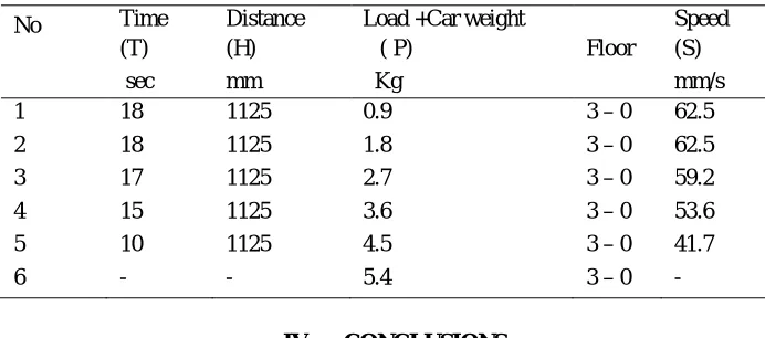
Table1 shows the parameters for constant load when the elevator car is moving up. It was observed that with a constant load, the speed of the elevator car remains the same from the down floor to the first, second and third floor. From table 2, the weights of the loads determine the time of travel of the elevator, that is, increase in load causes increase in time it takes to travel and therefore determine the speed at which the car travels from one distance to another.
[image:9.612.131.481.438.534.2]Therefore, the working load is 3.6kg and the maximum load is 4.5kg. The elevator car will not move at a load above 4.5kg as can be seen in table 2. As can be seen from the Table 3, increase in load causes decrease in time of travel of the elevator car.
Table 1
[image:9.612.132.481.565.706.2]Parameters for a constant load when the car is moving up.
Table 2
Parameters for a variable load when the car is moving up.
No
Time (T)
Distance (H)
Load +Car weight
( P) Floor
Speed (S)
sec mm kg mm/s
1 18 1125 0.9 0 - 3 62.5
2 18 1125 1.8 0 – 3 62.5
3 19 1125 2.7 0 – 3 59.2
4 21 1125 3.6 0 – 3 53.6
5 27 1125 4.5 0 – 3 41.7
6 - - 5.4 0 – 3 -
No
Time (T)
Distance (H)
Load +Car weight
( P) Floor
Speed (S)
Sec mm kg mm/s
1 6 375 0.9 0 –1 62.5
2 12 750 0.9 0 –2 62.5
©IJRASET: All Rights are Reserved
230
Table 3
Parameters for a variable load when the car is moving down.
No Time
(T)
Distance (H)
Load +Car weight
( P) Floor
Speed (S)
sec mm Kg mm/s
1 18 1125 0.9 3 – 0 62.5
2 18 1125 1.8 3 – 0 62.5
3 17 1125 2.7 3 – 0 59.2
4 15 1125 3.6 3 – 0 53.6
5 10 1125 4.5 3 – 0 41.7
6 - - 5.4 3 – 0 -
IV. CONCLUSIONS
This research work aims at designing and constructing a simple but effective elevator using cable and pulley system, and which will be powered by a D.C source. From the result obtained, the maximum load to be lifted by the elevator should not be exceeded as this will prevent the elevator car from moving and might also leads to gradual breakdown of the elevator. The importance of elevator in this century cannot be overemphasized; therefore it is necessary to always come up with better and improved designs to other elevators available in order to save cost in construction, installation and maintenance.
V. ACKNOWLEDGMENT
The authors express their gratitude to the research group that assisted during this research work
REFERENCES
[1] A.Moore, and C.Niall. “Developing Real-Time Systems using Object technology.” Real-time Perspection: Foundation and overview version 1. 2000 [2] H Kopetz. Real-Time Systems: Design Principles for Distributed Embedded Applications. Springer Science & Business Media. 2011
[3] Available: http://en.wikipedia.org/wiki/Elevator#History
[4] Available: http://www.us.schindler.com/sec_index/sec_kg/sec_kg_safety/sec_kg_profile_safety_elevatorsafetyfeatures.htm [5] Available: http://www.elevatorchallenge.com