6
I
January 2018
Study of Improvement in the Performance of Triple
Effect Vapor Absorption System Using Loop Heat
Pipes
Ankit Dwivedi1, R S Mishra2
1,2
Dept. of Mechanical Engineering, Delhi Technological University, Delhi
Abstract: The triple effect vapor absorption refrigeration system (VARS) works at higher temperatures (>150-160°C).This high
temperature working of the cycle helps in achieving higher COP I and COP II. This research analysis works on reducing the heat
input in the generators by use of two Loop Heat Pipes (LHPs) installed in the high and medium temperature levels. The
simulations have found that the improved COP I &COP II are 2.545 and 0.588 respectively. Also the percentage increase in
performances of the modified system has been recorded as 61.112 % and 25.146% respectively. Simulations also found that the
average TC can be maintained at 151.18 °C. The increase in the performance characteristics shows a positive gradient with the
increase in the temperature of operation of LHP. The average QLeak and QCond are found to be 89.44 kW and 71.68 kW
respectively.
I. INTRODUCTION
[image:2.612.192.430.434.667.2]Loop Heat Pipe (LHP) is an evaporator-condenser that works on the thermo-siphon effect. It operates and transfers heat without any requirement of input work. It acts as a super-conductor owing to the high heat transfer rates related to the evaporation and condensation. The heat pipe is a wicked structure, outside of which the heat is absorbed by the working fluid of the LHP from the ambient and the fluid gets vaporized. This vapor passes through the porous wicked structure and moved towards the condenser of the LHP through the Vapor Line. The vapor rejects heat in the condenser and gets condensed. These condensates then move towards the Compensation Chamber (CC) connected to the evaporator of the LHP and gets accumulated there.
Fig 1: Cyclic process of a Loop Heat Pipe [35]
Fig 2: Schematic of LHP [36].
A triple effect vapor absorption system refrigeration system (VARS) is used when the source temperature is high(>140-150 °C). The high temperature also corrodes the material of the generator and connecting lines. The parallel flow type heat exchanger is shown and explained in fig 3. This VARS system is very useful in utilizing a waste heat. The efficiency of the triple effect system is also relatively higher as the operating temperature is very high comparatively.
II. LITERATURE REVIEW
pipe systems permits raw length up to 100 m. They also described the establishment of the heat pump system in general. Ankit Dwivedi et al. (2018) through computer simulations of the replacement of condensers from single, double and half effect VARS, showed the improvements in the performance in COP I and COP II .Waste heat is being utilized in the cycle from some outside
source, while the cycle itself rejects heat at the saturation temperature of the refrigerant which in case is as high as the generator. This heat is taken away by the working fluid of the condenser (Air, Water etc). It can be taken away by the mixture of refrigerant from the absorber as well which already works at the condenser temperature. The LHP can be used for this purpose. It can replace the condenser and help in the intra cycle heat exchange. The two condensers working at higher temperatures (>100°C) can be replaced in the triple effect cycle by LHPs. The bulky condensers will be removed and flexile heat pipes will take its place. Also as mentioned earlier the LHPs will act as a superconductor with having higher capacity and higher heat transfer coefficient. Some of the research works have showed the options for more analysis in these aspects.
III. SYSTEMS DESCRIPTION
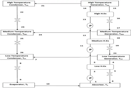
[image:4.612.93.542.363.670.2]It can be explained by the fig 3 what are the basic components and cycle processes of the triple effect VARS. This is a parallel flow triple effect system which has 3 condensers (Low(LC), Medium(MC) and High(HC)), 3 generators (Low(LG), Medium(MG) and High(HG)), an absorber, an evaporator, 3 Heat Exchangers (Low H.E x, MedH. Ex, HighH. Ex), pumping devices and throttle valves. The mixture is pumped to the high temperature generator HG (>working at 150°C) through the 3 heat exchangers. A major part of the rich refrigerant then gets separated from the mixture and is transferred through HC to the evaporator to produce the refrigeration. The remaining mixture from the HG then is throttled to the MG(>120°C) where it is heated and the separated strong refrigerant is transferred to the evaporator through MC and throttle valves. The remaining mixture from MG is then throttled to the LG(>80-90°C) where the above process takes place. Finally the remaining mixture is throttled to the absorber. This 3 stage process helps the separation strong refrigerant well administered.
Fig 3: A Triple Effect (Parallel) Vapour Absorption System
will be very simple when compared with that of H. Ex. Heat is removed at the evaporator size on the LHP from the condensing strong refrigerant. This heat will be transferred to the mixture coming from the absorber. The effectiveness on the the LHP will be higher than the other heat exchangers owing to the high heat transfer coefficients. The simulations are executed and the results are as follows. The table 1 consists of the terminology used in the analysis.
Fig.4: Modified Triple Effect Vapour Absorption System
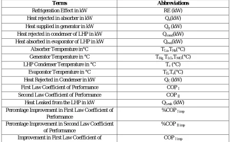
Table 1: Terms Used in Simulation
Terms Abbreviations
Refrigeration Effect in kW RE (kW)
Heat rejected in absorber in kW Qa(kW)
Heat supplied in generator in kW Qg (kW)
Heat rejected in condenser of LHP in kW Qcond(kW)
Heat absorbed in evaporator of LHP in kW Qeva(kW)
Absorber Temperature in°C TLa,THa(°C)
Generator Temperature in °C THg, TLG,TMG(°C)
LHP Condenser Temperature in °C Tc (°C)
Evaporator Temperature in °C TE,Te(°C)
Heat Rejected in Condenser in kW QC (kW)
First Law Coefficient of Performance COP I
Second Law Coefficient of Performance COP II
Heat Leaked from the LHP in kW QLeak (kW)
Percentage Improvement in First Law Coefficient of Performance
%COP I imp
Percentage Improvement in Second Law Coefficient of Performance
%COP II imp
[image:5.612.81.530.448.726.2]Performance
Improvement in Second Law Coefficient of Performance
COP II imp
Low Temperature Generator, Condenser LG,LC Medium Temperature Generator, Condenser MG, MC
High Temperature Generator, Condenser HG, HC
IV. RESULTS AND DICSUSSIONS
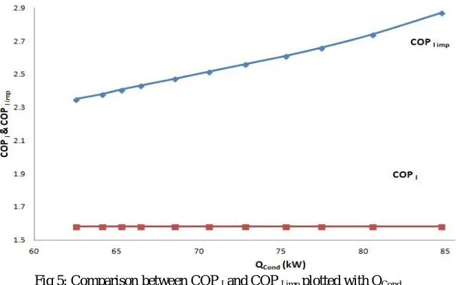
From Fig 5 to Fig 8 shows the various variations in COP I& COP II. Fig 5 describes the comparison of COP I improvement in the
[image:6.612.148.482.229.436.2]modified system and the COP I in the basic triple effect cycle. The average COP I of modified system can be observed to be 2.545.
Fig 5: Comparison between COP I and COP I imp plotted with QCond
It can be seen in the fig 6 how COP II of the proposed modified system stands against the original system. There’s a continuous
increase in the COP II, as the slope in the beginning is positive and in the later stage the increase in Q Cond may not yield in higher
[image:6.612.139.474.503.719.2]rises in COP II. The average COP II of modified system can be 0.588.
Fig 7 shows the increase in COP I& COP II relatively over the range of Q Cond. It can be seen that COP I has a higher and direct effect
of Q Cond as its being used in improving it directly. The COP II on the other hand doesn’t show a sharp rise as COP I does. The
[image:7.612.129.486.143.400.2]reduction of heat wastage in the system no doubt helps in decreasing the exergy loss. Both external and internal irreversibility are reduced.
[image:7.612.125.502.477.716.2]Fig 7: COP I and COP IIplotted with QCond
Fig 8 in a way is developed to show the percentage rise in the COPI and COP II owing to the use of LHPs. As discussed earlier the
COP I is directly affected by the Q Cond. Here the average percentage rise in COP Iis found to be around 61.112 % and the average
rise in COPII is 25.146%. Also if the designs can be changed so that LHPs are able utilize more heat and the leaks are reduced the
COP I can be further improved.
The Fig 9 & Fig 10 shows the percentage improvements in the performance with the range of LHP condenser temperature TC and
HG temperature TG. With the ranging TC rise in COP I has a positive slope as discussed earlier and as the TC increase further the
availability also increases. Increase in the availability helps in increasing COP I as the heat to be utilized increases. COP II also
follows, and increase in the COP II is recorded by the simulations.
Fig9: Comparison of %age improvements in COP I& COP II varying the TC
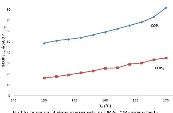
Fig 10 describes the variations of performance with the range of TG. With rise in TG the COPI has a sharp increase, whereas the
COPII has a gradual
[image:8.612.125.492.439.680.2]increase.
Fig 10: Comparison of %age improvements in COP I& COP II varying the TG
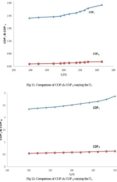
Fig 11: Comparison of COP I& COP II varying the TC
Fig 12: Comparison of COP I& COP II varying the TG
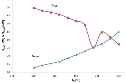
[image:9.612.122.488.77.328.2]Fig 13: Comparison of QLeak & QCond varying the TC
On the other hand, the figure below shows the same variation with temperature of HG. The heat leak QLeak is decreasing with the
[image:10.612.102.512.409.684.2]increase in TG. The average heat that has leaked the LHP is 89.44 kW over the ranges of temperatures.
Fig 14: Comparison of QLeak&QCond varying the TG
Fig 15: Variation of TC with the TG
[image:11.612.123.490.322.724.2]The Figure 16 to 19 the performance of the modified system can be studied with the variations in the working temperatures.
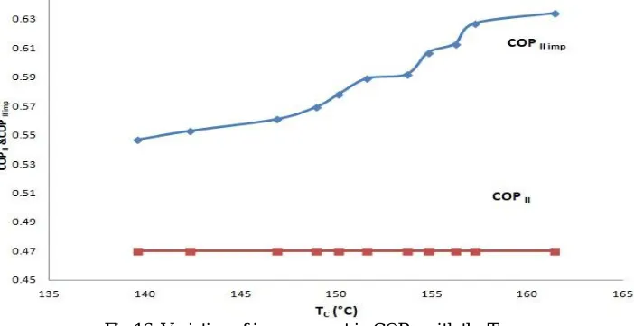
Fig 16: Variation of improvement in COP II with the TC
[image:11.612.137.488.344.525.2]Fig 18: Variation of improvement in COP I with the TG
Fig 19: Variation of improvement in COP I with the TC
V. CONCLUSIONS
Following the results of the simulations, following conclusions can be made A. The average improved COP I &COP II are 2.545 and 0.588 respectively.
B. The percentage increase in COP I &COP II can be observed to be 61.112 % and 25.146% respectively.
C. The COP Ihas a sharper rise over the range when compared to the COP II for the range of QCond.
D. The COP I shows an increasing slope for the entire range while the COP II shows a decreasing slope for the entire range of the
TG and TC.
E. Increase in the temperature TG provides the desirable results such as reduction in the QLeak and increase in QCond and average TC
is found to be is 151.18 °C.
[image:12.612.124.492.264.553.2]REFERENCES
[1] Saeed. Sedigh , Hamid. Saffari ,”Thermodynamic analysis of single effect and half effect absorption refrigeration system” International Journal of Energy & Technology Vol.25 (2011) 1-9
[2] S. Arivazhagan , R. Saravanan , S. Renganarayanan ,” Experimental studies on HFC based two-stage half effect vapour absorption cooling system” Applied Thermal Engineering Vol. 26 (2006) 1455–1462
[3] ulshanSachdeva, Ram Bilash,” Thermodynamic Analysis of a Vapor Absorption System Using Modified Gouy-Stodola Equation” International Journal of Computer, Electrical, Automation, Control and Information Engineering Vol:8, No:12, 2014
[4] I. Horuz,” A comparison between Ammonia-water and Water-Lithium Bromide solutions in Vapor Absorption Refrigeration Systems” Int. Comm. Heat Mass Transfer, Vol. 25, No. 5, pp. 711-721, 1998
[5] Abdul Khaliq, and Rajesh Kumar,” Exergy analysis of double effect vapor absorption refrigeration system” Int. J. Energy Res. 2008; Vol.32:161–174
[6] S.C. Kaushika, AkhileshArora,” Energy and exergy analysis of single effect and series flow double effect water–lithium bromide absorption refrigeration systems” international journal of refrigeration Vol.32 ( 2009 ) 1247 – 1258
[7] RabahGomri , RiadHakimi,” Second law analysis of double effect vapour absorption cooler system” Energy Conversion and Management Vol.49 (2008) 3343– 3348
[8] S.A. Adewusi, Syed M. Zubair,” Second law based thermodynamic analysis of ammonia–water absorption systems” Energy Conversion and Management Vol. 45 (2004) 2355–2369.
[9] RabahGomri,” Second law comparison of single effect and double effect vapour absorption refrigeration systems” Energy Conversion and Management Vol. 50 (2009) 1279–1287
[10] M. Belghazi, A. Bontemps, C. Marvillet,” Experimental study and modelling of heat transfer during condensation of pure fluid and binary mixture on a bundle of horizontal finned tubes” International Journal of Refrigeration Vol.26 (2003) 214–223.
[11] M.M. Talbi, B. Agnew,” Exergy analysis: an absorption refrigerator using lithium bromide and water as the working Fuids” Applied Thermal Engineering Vol. 20 (2000) 619-630
[12] E. Kurem,” A comparison between Ammonia-water and Water-Lithium Bromide solutions in vapour absorption heat transformers “In. Comm. Heat Mass Transfer; Vol. 28, No. 3, pp. 421-438, 2001
[13] Da-Wen Sun,” Comparison of the performances and NH3-H20, NH3-LiNO3 and NH3-NaSCN VaporAbsorption Refrigeration Systems” Energy Convers. Mgmt Vol. 39, No. 5/6, pp. 357-368, 1998
[14] Yu.F. Maydanik,” Review Loop heat pipes” Applied Thermal Engineering Vol.25 (2005) 635–657
[15] Randeep Singh, AliakbarAkbarzadeh , MasatakaMochizuk,” Operational characteristics of a miniature loop heat pipe with flat evaporator” International Journal of Thermal Sciences Vol.47 (2008) 1504–1515
[16] T.X. Li, R.Z. Wang , L.W. Wang, Z.S. Lu, C.J. Chen,” Performance study of a high efficient multifunction heat pipe type adsorption ice making system with novel mass and heat recovery processes” International Journal of Thermal Sciences Vol.46 (2007) 1267–127
[17] Yuan-Ching Chiang , Wen-Cheng Kuo , Chia-CheHo , Jen-JieChieh,” Experimental study on thermal performances of heat pipes for air-conditioning systems influenced by magnetic nanofluids, external fields, and micro wicks” International Journal of Refrigeration Vol.43 ( 2014 ) 62 -70
[18] T.X. Li, R.Z. Wang, L.W. Wang, Z.S. Lu,” Experimental investigation of an innovative dual-mode chemisorption refrigeration system based on multifunction heat pipes” International Journal of Refrigeration 3 1 ( 2 0 0 8 ) 1 1 0 4 – 1 1 1 2
[19] L. GarousiFarshi a,*, C.A. Infante Ferreira b, S.M.S. Mahmoudi a, M.A. Rosen,” First and second law analysis of ammonia/salt absorption refrigeration systems” International Journal of Refrigeration Vol. 4 0 ( 2 0 1 4 ) 1 1 1-1 2 1
[20] T.X. Li, R.Z. Wang , L.W. Wang, Z.S. Lu, J.Y. Wu,” Influence of mass recovery on the performance of a heat pipe type ammonia sorption refrigeration system using CaCl2/activated carbon as compound adsorbent” Applied Thermal Engineering Vol. 28 (2008) 1638–1646
[21] Z.S. Lu , L.W. Wang, R.Z. Wang,” Experimental analysis of an adsorption refrigerator with mass and heat-pipe heat recovery process” Energy Conversion and Management Vol. 53 (2012) 291–297
[22] Behrooz M. Ziapour*, Mohsen Tavakoli,” Performance study on a diffusion absorption refrigeration heat pipe cycle” International Journal of Thermal Sciences Vol.50 (2011) 592-598
[23] Basant K. Agrawal*, Munawar N. Karimi,” Thermodynamic performance assessment of a novel waste heat based triple effec refrigeration cycle” International Journal of Refrigeration Vol. 3 5 ( 2 0 1 2 ) 1 6 4 7-1 6 5 6
[24] Behrooz M. Ziapour*, Mohsen Tavakoli,” Performance study on a diffusion absorption refrigeration heat pipe cycle” International Journal of Thermal Sciences 50 (2011) 592-598
[25] T.S. Jadhav , M.M. Lele,” Theoretical energy saving analysis of air conditioning system using heat pipe heat exchanger for Indian climatic zones” Engineering Science and Technology, an International Journal Vol. 18 (2015) 669-673
[26] Chengchu Yan , Wenxing Shi , Xianting Li , Shengwei Wang,” A seasonal cold storage system based on separate type heat pipe for sustainable building cooling” Renewable Energy Vol.85 (2016) 880-889
[27] Matthias H. Buschmann,” Nanofluids in thermosyphons and heat pipes: Overview of recent experiments and modelling approaches” International Journal of Thermal Sciences Vol.72 (2013) 1-17
[28] P.D. Dunn, D.A. Reay, Heat Pipes, Pergamon Press, Oxford, 1993
[29] D.Reay, Heat Pipes-Theory, Design and Applications, Butterworth-Heinemann,Oxford, Fifth edition 2006
[30] Korn, F., “Heat Pipes and its Applications” Project Report 2008 MVK160 Heat and Mass Transport May 07, 2008, Lund, Sweden
[31] Rajashree, R., Rao, K.S., “A Numerical Study of the Performance of Heat Pipe” Indian Journal of Pure and Applied Mathematics, 21 (1): 95-108, January 1990 [32] C.P. Arora, Refrigeration and Air Conditioning, Tata Mcgraw-Hill Publishing Company Limited,Delhi, Third Edition, 2009
[33] AnkitDwivedi, R. S. Mishra,” Thermodynamic Analysis of Heat Pipe Using Ammonia, Water and Ethanol with a View to Being Used in Refrigeration” ISSN 2347 - 3258 International Journal of Advance Research and Innovation, Volume 3, Issue 3 (2015) 498-502
[35] http://hexus.net/tech/news/cooling/81583-fujitsu-thin-loop-heat-pipe-cooler-said-5x-efficient/ [36] https://www.tut.ac.jp/english/schools/faculty/me/post_6.html
[37] AnkitDwivedi, R. S. Mishra,” Performance Enhancement of Simple Vapour Absorption System Using Loop Heat Pipes” ISSN: 2321-9653 International Journal for Research in Applied Science & Engineering Technology (IJRASET), Volume 6 Issue I, January 2018, 865-873.
[38] AnkitDwivedi, R. S. Mishra,” Study of Performance Enhancement of Half Effect Vapor Absorption System Using Loop Heat Pipes” ISSN: 2321-9653 International Journal for Research in Applied Science & Engineering Technology (IJRASET), Volume 6 Issue I, January 2018, 1147-1156.
![Fig 1: Cyclic process of a Loop Heat Pipe [35]](https://thumb-us.123doks.com/thumbv2/123dok_us/8297677.853399/2.612.192.430.434.667/fig-cyclic-process-loop-heat-pipe.webp)
![Fig 2: Schematic of LHP [36].](https://thumb-us.123doks.com/thumbv2/123dok_us/8297677.853399/3.612.166.446.79.235/fig-schematic-of-lhp.webp)