5
IX
September 2017
Development and Implementation of Low-Cost
Pedagogic Tools in Computer-Aided Design and
Computer-Aided Manufacturing
Dr. Ruvel J. Cuasito1, Sr., PECE2 1, 2
College of Technology, University of Science and Technology of Southern Philippines
Abstract: This paper presents potent academic initiatives in addressing skill set demands in the computer aided design and computer aided manufacturing (CAD-CAM) fields as benchmark information to facilitate academic instruction. Through the integration of computer-aided design (CAD) and computer-aided manufacturing, skills in G-Code program and CAD design can now be translated into mechanical actions through the KCAM software. The study sought to develop an open-loop computer numerical control trainer applied to milling and lathe operations that offers skill set to the students in three areas: G-Code programming, CAD, and CAM operations. This study highlights the design, development, implementation and evaluation of an open-loop milling and lathe CNC machines. The instructional tools utilized second-hand stepper motors positioned in multiple axes point through the use of appropriate motor drivers. The implementation of CAD-CAM operations was achieved through the use of existing KCAM software that provided compatible interfacing with CAD to CAM operations. The trainers were evaluated using pre-established parameters with emphasis on system’s performance, aesthetics, quality, cost effectiveness, mobility, and safety. The system’s performance of the CNC machines mimic real CAD-CAM operations using G-code programming and/or CAD design importation into the KCAM software. The linear and angular displacements showed discrepancies during simulation and actual real time machining. However, the aforementioned differences were easily complemented through dimensional offsetting and programming during axis table set-up. The locally-assembled pedagogic tools in CAD-CAM course provided economic and academic impact to the students of University of Science and Technology of Southern Philippines (USTP), Cagayan de Oro City, Philippines. The study outcome also serve as baseline research for other third world countries to initiate educational tool development using indigenous materials for their own academic consumption to save on cost.
Keywords: computer numerical control, computer-aided manufacturing, pedagogic tools, milling machine, lathe machine
I. INTRODUCTION
II. OBJECTIVES
The study sought to develop an open-loop computer numerical control trainer applied to milling and lathe operations that offers skill set in modern manufacturing technology to the electro-mechanical technology students in three areas: G-code programming, CAD, and CAM operations. The purpose of which is not to introduce new CNC technology but to introduce alternative academic instruction delivery through low-cost educational tool development. Specifically, the study focused on the development, implementation, and performance evaluation of the low-cost CNC trainers in accordance to the design parameters established.
III. MATERIALS AND METHODS
A. The Development and Implementation
The fundamental design follows an open-loop control system that operates without verifying the actual position of a specified tool position. The system design do not have complete feedback control system which means that operation errors are not evaluated and corrected by the system. The development and implementation of the projects are anchored on the aforementioned control system. Google sketchUp software was utilized in the concept designs.
B. The Power Supply Design
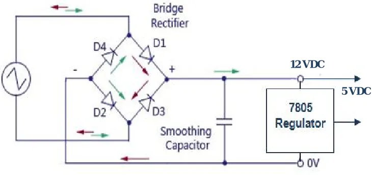
Figure 1, shows the basic full wave bridge-type power supply which is used to provide power to the stepper motor in the CNC milling and lathe machines in this study. The full wave power supply (Loflin, 2010) intends to produce 12 VDC for the stepper motor and 5 VDC for the low-cost drill. On the other hand, Figure 2 shows the half wave power supply design that is utilized to drive the DC motor to rotate the chuck that serves as work piece holder in the CNC lathe machine. This power supply intends to provide 12 VDC.
12 VDC
[image:3.612.134.499.348.520.2]5 VDC
Figure 1: Full wave power supply (bristolwatch.com)
[image:3.612.159.452.559.715.2]C. The motor Driver
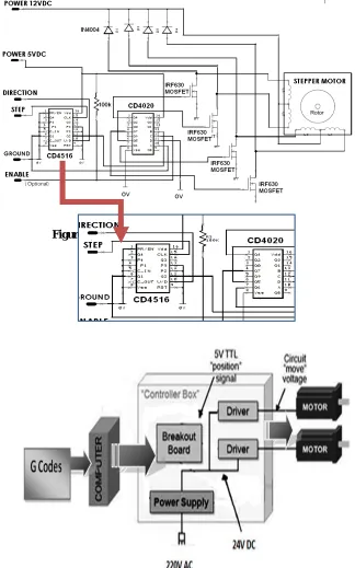
The stepper motor driver is designed in accordance to the available schematic diagram retrieved from the internet resources (Instructables.com, 2009). The corresponding electronic components were purchased locally in Cagayan de Oro City, Philippines. The motor driver is designed to drive multiple motors which can be controlled via electronic interfacing and computer programming. The trainer utilized the KCAM control software version 4 (Kellyware.com, 2009), which perform a variety of functions like routing, milling, drilling, and cutting. The file format utilized in this prototype is G-code, DXF, EXELION &
GERBER. Figure 3 shows the stepper motor driver schematics. The CNC block diagram is shown in Figure 4 depicting the
[image:4.612.148.472.186.705.2]software-control box, and stepper motors.
Figure 3: The stepper motor driver (Instructables.com)
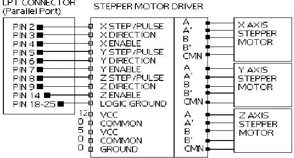
The Motor driver is interfaced via the LPT parallel port of a personal computer as shown in Figure 5 using the parallel port-motor driver schematics.
Figure 5: The Parallel Port Interfacing circuit
D. The CNC Milling Machine
The mechanical design of the CNC milling machine is shown in Figure 6 with its corresponding dimensional data.
Figure 6: The mechanical frame
[image:5.612.169.424.333.496.2]In Figure 7, two aluminum U channels were screwed in the angle bar frame according to the specified measurements. Flexi glass was then attached atop and serves as the X axis table. As shown in the figure, the axis table top profile used for x, y and z axis flat form (Instructables.com, 2009). In between the U channels, the stepper motor is fixed at the same time attached to a locally available stud bolt. The coupling used is polyurethane tubing forced fitted into the motor shafting and the bolt.
The Y axis assembly was in placed atop X axis table through fastened U channels. In between them, the Y axis stepper motor is fixed. The Y axis flexi glass table top moved via stud bolt attached to the Y axis stepper motor. The axis table is attached to the vertical frame using a pair of U channels perpendicular in placed with respect to the X and Y axis motor drives the table vertically. The Z axis served as the mounting plate for the spindle represented by a low-cost drill. The drill is driven by a DC motor which is installed vertically and positioned to the work piece to be engraved accordingly. Through the KCAM software, the designed figure for engraving can be successfully implemented using the acceptable G-Code programming or via CAD design importation.
E. The CNC Lathe Machine
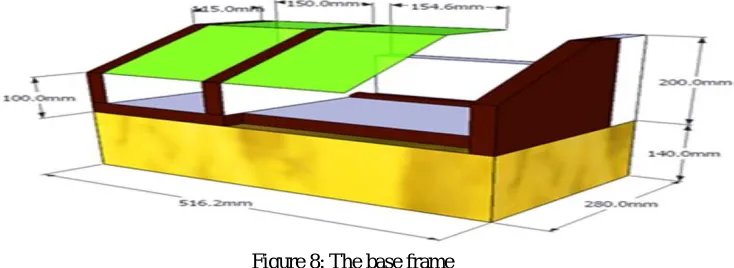
[image:6.612.130.497.202.336.2]Figure 8 shows the CNC lathe machine base frame made of wood and thermo-plastic.
Figure 8: The base frame
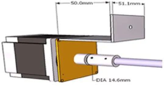
[image:6.612.153.457.401.551.2]The X-axis of the lathe machine is driven by a stepper motor connected to a screw shafting as shown in Figure 9. The X-axis is placed atop the Y-axis where the tool bit is attached and positioned to engage machining on a soft material workpiece as shown in Figure 10.
[image:6.612.142.448.605.706.2]Figure 9: The CNC lathe machine X-axis design
Figure 11 shows the Y-axis stepper motor connected to a screw shafting to drive the axis via a coupling. The Y-axis drives the X-axis table-top accordingly. The CNC lathe machine design concept is depicted in Figure 12.
[image:7.612.160.443.112.443.2]Figure 11: The Y-axis motor
Figure 12: The CNC lathe machine design concept
F. The Evaluation
Performance evaluation of the CNC machines were assessed by comparing the actual and simulated displacements based on designed parameters. Corresponding measurements were conducted to validate accuracy and complementary measures were made to compensate and correct errors.
Descriptive statistics is used in the evaluation of the systems’ performance using the five (5) rating scale with the following adjectival ratings:
Adjectival Rating Scale Range
1 – Very Poor 1.4 - below
2 – Poor 1.5 – 2.4
3 – Satisfactory 2.5 – 3.4
4 – Very Satisfactory 3.5 – 4.4
5 – Outstanding 4.5 – above
Purposive sampling is used in the survey by dispatching survey questionnaires to students and instructors aligned with computer-aided design and computer-computer-aided manufacturing courses in University of Science and Technology of Southern Philippines (USTP), Cagayan de Oro City, Philippines.
IV. RESULTS AND DISCUSSIONS
A. The CNC Milling Machine
This CNC machine utilizes a bridge type power supply that provides 12 VDC and 5 VDC, at 3 Amps current rating. Figure 13
Figure 13: The power supply
[image:8.612.152.463.302.494.2]The stepper motor driver shown in Figure 14 is implemented in accordance to the existing schematic design sourced via internet resources. The circuit board is placed in the control box where the corresponding electronic components were purchased in locally in Cagayan de Oro City, Philippines.
Figure 14: The motor driver circuit
The trainer utilized the KCAM control software version 4, which performs a variety of functions like routing, milling, drilling, and cutting. KCAM is capable of reading files created according to the designed applications and control CNC machines via parallel port of a personal computer (PC). As shown in the figure above, the stepper motor driver circuit is mounted in an enclosure. Figure 15 depicts the CNC milling machine showing the axes stepper motors and the driver circuit control box were attached.
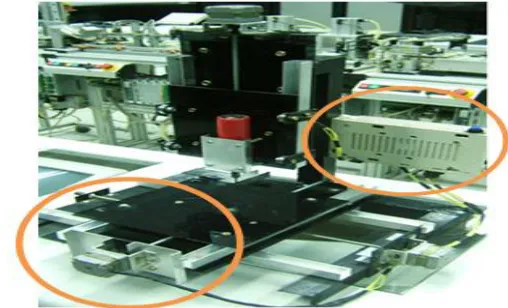
[image:8.612.164.418.563.717.2]Figure 16 shows the CNC Milling trainer with its corresponding stepper motors for X, Y, and Z axes drivers.
[image:9.612.123.497.328.518.2]Figure 16: The multiple axes drivers
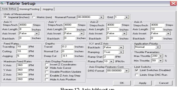
Figure 17: Axis-table set-up
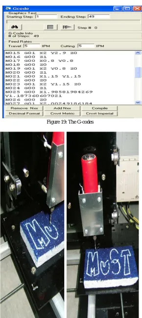
Figure 17 and Figure 18 shows the screen shots of the axis and/or table set-up as well as the actual CAD design using CAD respectively which was imported to the KCAM software. This design was interpreted electronically and eventually executed by the CNC milling machine. Figure 19 shows the snapshots of the trainer’s actual performance during G-Code programming and engraving tasks shown in Figure 20.
[image:9.612.143.443.593.718.2]Figure 19: The G-codes
Table 1: Performance of milling machine
Trial Axis Displacement
X-axis Y-axis Z-axis
Simulated Actual Simulated Actual Simulated Actual
1 1.0 in. 1.01 in 1.0 in. 1.02 in 1.0 in. 1.02 in
2 1.0 in. 1.02 in 1.0 in. 1.02 in 1.0 in. 1.02 in
3 1.0 in. 1.02 in 1.0 in. 1.02 in 1.0 in. 1.02 in
% Error 0% 2.0% 0% 2.0% 0% 2.0%
Table 1 shows the performance evaluation result which yielded 2% errors in actual runs in all axes. However, the problem was complemented through KCAM dimensional entry offsetting.
B. The CNC Lathe Machine
The study undertakes project concept improvement of the CNC milling machine developed by the Electro-mechanical Technology department of the University of Science and Technology of Southern Philippines (USTP), Cagayan de Oro City, Philippines. The project is designed to mimic real manufacturing applications and to serve as an instructional tool intended to supplement laboratory
instruction in the fields of computer-aided design and computer-aided manufacturing courses of the university. Figure 21 shows the
[image:11.612.136.468.349.507.2]developed X-axis driver using the stepper motor while on actual machining. Depicted also in the figure is the Y-axis where the tool bit holder is securely attached. The work piece utilized soft materials like plastic and light wood.
[image:11.612.132.467.549.707.2]Figure 21: The X-axis and Y-axis tool bit holder
The Y-axis stepper motor is attached accordingly as shown in Figure 22 as well as thechuck belt-driven by the DC motor. Figure
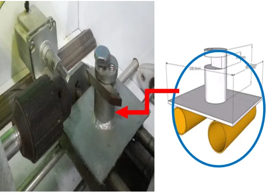
[image:12.612.165.438.103.303.2]23 shows the how the tool bit holder is attached to the Y-axis with a bolt.
Figure 23: The tool bit holder
[image:12.612.165.459.381.560.2]The prototype offers significant cost savings to the university for instead of purchasing expensive CNC machines for laboratory instruction, the localized CNC Lathe Machine developed by the students and instructors suffice the training requirements set by the industry. Figure 24 and Figure 25 depict the final trainer securely covered by thermo-plastic while on actual machining on a plastic work piece. The figure below also shows the control box containing the power supply of the CNC lathe machine.
Figure 24: The CNC lathe machine trainer
[image:12.612.169.455.593.717.2]Table 2 that shows the technical test results suggest the actual performance and efficiency of the CNC Lathe machine training tool. X axis & Y axis simulated trials yielded no errors. However, actual test run registered 2% error. These errors were eventually complemented by adjusting the dimensional entry during axis set-up taking careful consideration the percentage error at 2%. By offsetting the aforementioned error the final outcome based on actual results of the machining yielded no errors.
Table 2: The CNC lathe machine performance
Trial Axis Displacements
X-axis Y-axis
Simulated Actual Simulated Actual
1 1.0 in 1.02 1.0 in 1.02
2 1.0 in 1.02 1.0 in 1.02
3 1.0 in 1.02 1.0 in 1.02
% Error 0% 2% 0% 2%
[image:13.612.126.489.396.472.2]C. Overall Acceptability Evaluation
Table 3 shows the summary of mean responses of the survey participants utilizing pre-established evaluation parameters relative to its functionality, aesthetics, complexity, and marketability. Descriptive statistics was used to evaluate the technical judgments of the respondents on their respective perception on the acceptability of the CNC trainers accomplished. Purposive sampling was utilized by selecting students and instructors who were taking or teaching CAD-CAM courses in USTP.
Table 3: Summary of mean responses
Parameters Mean Adjectival Rating
Functionality 4.13 Very Satisfactory
Aesthetics 4.32 Very Satisfactory
Complexity 3.94 Very Satisfactory
Marketability 4.16 Very Satisfactory
The overall result yielded response from the survey participants with the registered mean ratings in the very satisfactory adjectival rating. The ratings in the technical performance of the trainers were attributed to the versatility and flexibility of the instructional tools as it can easily be adjusted to offset dimensional gaps during machining operations. As to the aesthetics, the respondents affirmed very satisfactory mean ratings on the physical appearance and workmanship of the trainers. However, the survey participants also confirmed the complexity of the development of the CNC machines.
The cost of production of the trainers for commercial purposes is pegged at One Hundred Thousand Pesos (P 150,000.00) per unit that includes among others the system unit, laboratory manual, and training for 40 hrs.
V. CONCLUSIONS
The development of a locally assembled CNC machines that performs milling and lathe operations supplement instruction delivery in the areas of computer aided manufacturing. It complements theoretical learning aspect with actual CNC control manipulations and programming. Its designed purpose satisfies the desired learning outcome in CAD-CAM operations as indicated by the very satisfactory affirmation of the trainers’ acceptability evaluation.
VI. RECOMMENDATIONS
The CNC machine is recommended for training and instruction purposes only. It is advisable that the pedagogic tools should only use soft work pieces to preserve its efficiency. To improve the marketability of the trainers, the aesthetics may be further improved. Future works are directed towards using precision servomotors to eliminate the 2% errors incurred during actual run.
Although this research projects were implemented in the Philippines, this academic initiative of developing indigenous instructional laboratory equipment may also be replicated in other third-world countries. Through locally assembled CNC machines, higher education and technical vocational institutions in the country may be able to exercise self-sufficiency by imparting technology-based treatment to some academic shortcomings and prepare human resources to global competitiveness in the CAD-CAM market.
VII. REFERENCES
[1] Bettersworth, M., Texas State Technical College, http://www.system.tstc.edu, [Accessed 1/16/2012].
[2] Del Guera, Coelho (2006), Development of a Low-Cost Touch Trigger Probe for CNC Lathes. Journal of Materials Processing Technology [3] Easy to build CNC Mill Stepper Motor & Driver Circuits, Retrieved January 26, 2009, http://instructables.com
[4] Easy to build Desktop 3 axis CNC Milling Machine, Retrieved January 26, 2009, http://instructables.com
[5] ElectronicsTutorials, Miscellaneous Circuits, Half-wave Power Supply, retrieved from http://www.electronics-tutorials.ws, [accessed January 28, 2012]. [6] Ishebe, T. (2007), “Putting the “T” Back to IT: Developing the IT Management Agenda for the Mid-1990’s” SIM Executive Brief.
[7] KCam 4, CNC Control Software, Retrieved January 24, 2009, http://kellyware.com
[8] Khemani, H. (2008), What is CAD-CAM?, Bright Hub Engineering, [Accessed 1/15/2010] http://www.brighthubengineering.com