Enhancement of Coefficient of Performance of
Vapor Compression Refrigeration System Using
Diffuser at Inlet of Condenser
Mr. Nurul Seraj1, Dr. S. C. Roy2
1Student, 2Head of Department, Department of Mechanical Engineering, B.I.T Sindri, Dhanbad, Jharkhand-828123
Abstract: To Enhanced the Coefficient of Performance, It is to require that Refrigerating Effect Should Increase and Compressor Work should decrease. Experimental analysis on vapour compression refrigeration (VCR) system with R134a refrigerant was completed and their results were recorded. The effects of the main parameters of performance analysis such as super heating on the refrigerating effect, power required to run the compressor for various evaporating temperatures, mass flow of refrigerant, percentage increase in COP, coefficient of performance (COP). The results from vapour compression refrigerant plant was taken where the variables like suction pressure of compressor, delivery pressure of compressor, temperature of evaporator and condenser are noted and coefficient of performance is calculated. Initially The Diffuser Of Increasing Cross-Sectional Area Profile Was Designed, Fabricated And Introduced In Our VCR Apparatus. The Size Of Diffuser Selected Was Of 15 Degree Divergence Angle. By Using Diffuser Power Consumption Is Less For Same Refrigerating Effect So Performance Is Improved. The Size Of The Condenser Can Also Be Reduced Due To More Heat Transfer. So Cost Of The Condenser Will Be Reduced. The Parameters Pressure And Temperature Were Measured.
Keywords:- VCR System, COP, Diffuser, Divergence angle.
I. INTRODUCTION
The most frequently used refrigeration cycle is the vapour compression refrigeration cycle. In vapour compression refrigeration system condenser is used to remove heat from high pressure vapor refrigerant and converts it into high pressure liquid refrigerant. The refrigerant flows inside the coils of condenser and cooling fluid flows over the condenser coils. Condenser used in domestic vapour compression refrigeration system is air cooled condenser, which may be naturally or forced air cooled. Heat transfer occurs from the refrigerant to the cooling fluid i.e., outside air. High pressure liquid refrigerant flows through an expansion device to obtain low pressure refrigerant. Low pressure refrigerant flows through the evaporator. The two phase refrigerant in the evaporator enters into heat exchange relationship with secondary fluid to regulate the temperature of the secondary fluid that is circulated to regulate it, of an area inside the structure. Liquid refrigerant in the evaporator absorbs latent heat and get converted into vapour refrigerant which returned to compressor. Compressor raised the pressure and temperature of the vapour refrigerant and discharged into the condenser to complete the cycle.
II. OBJECTIVE OF RESEARCH
A. To enhanced the coefficient of performance of vapour Compression refrigeration system by substituting diffuser at inlet of condenser.
B. To compare the performance of system with and without diffuser.
C. Experimental detail
In the present cycle, the vapour refrigerant leaves the compressor with comparatively high velocity. This high velocity refrigerant directly impinges on the tubing of condenser which may cause damage to it by vibration, pitting or erosion. It results undesirable splashing of refrigerant in the condenser coil. It also results a phenomenon called as “liquid hump”. Liquid hump refers to a rise in the level of the condensed refrigerant liquid in the central portion of the condenser as compared to the level at the ends of the condenser. It reduces the effective heat transfer surface area which can reduce condenser efficiency.
recovery. Due to pressure recovery, at same refrigerating effect, compressor has to do less work. Hence, power consumption of the compressor will be reduced which results improvement in system efficiency. As the refrigerant flow passes through the diffuser, pressure as well as temperature will be increased. In air cooled condenser, for constant air temperature, temperature difference between hot and cold fluid will be increased. Amount of heat rejected from condenser will be rise. To remove the same amount of heat, less heat transfer area will be required. Using the diffuser at condenser inlet will provide an opportunity to use a smaller condenser to achieve the same system efficiency. Use of diffuser will also provide an advantage of reducing the effect of starvation in vapour compression refrigeration systems. The cross-sectional area of diffuser should reduce in the flow direction for supersonic flows and should increase for subsonic flows. The velocity of refrigerant leaving the compressor is sub-sonic. Hence, cross-sectional area of diffuser should be increasing.
Diffuser’s inlet and outlet diameters were designed. To design length of diffuser equation ( 1 ) is developed from Figure4.3 L = AB = ( )/ --- ( 1)
Relation between length and divergence angle of diffuser plotted as shown in Figure 1. With increase in divergence angle of diffuser, its length is reduced for same inlet and outlet diameters.
Geometry of diffuser(D/L=0.6)
Inner diameter=20 mm Outer diameter=38mm Angle of divergence=15
Length of diffuser=33.5mm
L = AB = ( )/
Fig 1 Geometry of diffuser
D. Steps to making diffuser
To make the diffuser a metal plate is required.
1) Marking the metal plate with required size.
2) Scribing the metal plate at 60 angle.
3) Cut the scribing plate with help of Straight snip.
4) Work on Sheet bending machine to bending the cutting plate.
5) Work on edge folding machine to fold the edge of the shape.
6) Use Round bottom stake to making round shape.
7) Use Funnel stake for hammering
8) Wooden mallet a wooden hammer to make desire shape.
9) Weld the bend section and cross section of final shape.
E. Tool required in an experiment 1) Tube cutter.
2) Tube bender.
3) Flaring too
III. EXPERIMENTAL SETUP
[image:4.612.90.523.162.381.2]This experimental setup has been carried out to investigate the coefficient of performance of VCR system with diffuser at inlet of condenser. This setup has been fabricated in the heat engine laboratory at BIT, sindri .This is possible as study of the basic schematic diagram of experimental test set up shown in figure 4.11 and with observing basic principle of design and assembly of refrigeration system. Its overall view is shown in figure 4.13 the laboratory experiments were then carried out with main objective to investigate the possibility of pressure jump on the diffuser.
Fig 2 schematic diagram of experimental test set up
A. Working principle of experimental setup
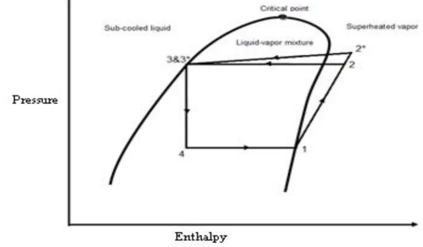
The novel experimental which is carried out in laboratory undergoes various processes during working of this new refrigeration system. Which is illustrates with P-h chart shown in figure 4.12
[image:4.612.92.513.461.707.2]Fig 4 schematic diagram of installed setup (In above figure temperature of evaporator is −15.6 )
B. Experimental measurement Without diffuser
(Psi) (Psi) (Psi) (Psi)
5 140 140 5
(0 ) (0 ) (0 ) (0 ) 31.6 42.7 33.8 -15
C. Experimental measurement With diffuser
(Psi) * (Psi) (Psi) (Psi)
5 148 148 5
(0 ) * (0 ) (0 ) (0 )
33.1 44.5 34.0 -15.2
D. Where
= Suction Pressure = Discharge Pressure
* = Pressure at the exit of diffuser = Pressure at the exit of condenser = Pressure at the exit of expansion device = Suction temperature
= Discharge temperature
* = Temperature at the exit of diffuser = Temperature at the exit of condenser = Temperature at the exit of expansion valve
E. Note
Net Refrigeration effect is maintained constant with the help of the variable speed drive to the compressor in both the systems of with and without diffusers.
Diffuser work ( )= ℎ ∗ - ℎ
Refrigeration effect (R.E) = ℎ - ℎ
For same refrigeration effect ℎ = ℎ ′ =ℎ
Reduction in compressor work = compressor work – diffuser work =( ℎ - ℎ ) – (ℎ ∗ - ℎ )
From the p-h chart of R-134a as shown in figure in , the following values can be obtained.
ℎ = 448kj/kg
ℎ′ = 498kj/kg
ℎ ∗ = 503kj/kg
ℎ = ℎ ′ =ℎ = 248kj/kg
Compressor work (W.D) = ℎ ′ - ℎ = 498 – 448 =50kj/kg
Diffuser work ( ) = ℎ ∗ - ℎ = 503 - 498 = 5kj/kg
Refrigeration effect = ℎ - ℎ
= 448 – 248 = 200kj/kg
Reduction in compressor work = (ℎ -ℎ ) – (ℎ ∗ -ℎ ) = (498 – 448) – (503 – 498) = 50 – 5
= 45kj/kg
= = = 4 = 4
=
= = 40/9 = 4.444
= 4.444
Hence the cop increased in vapour compression refrigeration system. Increased COP = -
= 4.444 – 4.000 = 0.444
Increased in COP = 0.444
Percentage increased in COP = ×100 = .
. ×100
= 9.009 %
E. Result
It is clear that from above is greater than .
Hence we can say that COP increased by 9.009% in vapour compression refrigeration system when diffuser is introduced at inlet of condenser.
F. Now we want to find heat extract from condenser
heat removed from condenser when diffuser is not used=250kj/kg Heat removed from condenser when diffuser is used is.
= ℎ *- ℎ = 503 – 248 = 255kj/kg
heat removed from condenser when diffuser is used = 255kj/kg
1) Result: From above it is also clear that the heat removed from condenser is increased when diffuser is used at inlet of condenser in vapour compression refrigeration system.
Another method to finding COP:-
ℎ = enthalpy of vapour refrigerant at , i.e. at suction of compressor and,
ℎ′ = Enthalpy of vapour refrigerant at temperature , i.e. at discharge of compressor without diffuser.
ℎ * = Enthalpy of vapour refrigerant at temperature , i.e. at discharge of compressor with diffuser.
ℎ = ℎ = Sensible heat at temperature , i.e. enthalpy of liquid refrigerant leaving of condenser. = Coefficient of performance without diffuser.
= Coefficient of performance with diffuser.
Experiment calculation is taken from Table 01 & Table 02
Table:-The value of enthalpy at different evaporator temperature from p-h chart is. Evap. temp. in 0c ℎ In kj/kg ℎ′ In (kj/kg) ℎ * In (kj/kg)
ℎ = ℎ
In (kj/kg)
R.E (Kj/kg)
WD
(Kj/kg) ℎ∗ − ℎ ′
(kj/kg)
Reduc. in work
WD-(kj/kg)
7.75 483 512 518 246 237 29 6 23 -4-9 463.5 501 505 246 217.5 37.5 4 33.5 -8.3 458.5 500 504 246 212.5 41.5 4 37.5 -9.3 453 498 502 248 205 49 4 45 -13.1 452 497 501 249 203 49 4 45 -15 448 498 503 248 200 50 5 45
Table: - Calculated value of COP for different temperature of evaporator with and without diffuser.
COP = =
COP = = ( ∗ )
Evaporator temperature in ( )
Fig.5 Graphical representation of COP1&COP2 vs Evaporator temperature
Average value of = . . . = . = 5.2365 Average value of = 5.2365
Average value of = . . . = . = 5.9949 Average value of = 5.9949
Now, increase in the value of COP is = -
= 5.9949 – 5.2365 = 0.7584
increase in the value of COP = 0.7584 Also, percentage increases in the value of COP is
= ×100 = .
.
= 14.48%
2) Result: From above it clear that when average value of COP with & without diffuser is taken at different evaporator temperature then percentage increased in COP is 14.48%. Which is more than the previous value of COP =9.009% calculated.
REFERENCES
[1] R.S. J K Gupta“ A Textbook of Refrigeration and Air Conditioning”, „S Khurmi Chand & Co Ltd publication‟2006,pp. 306-313,727-730 [2] Rajput R.K. “A Textbook of Refrigeration and Air-Conditioning”, S.K.Kataria & Sons publication “2012,pp.96-11
[3] Amitprakash “IMPROVING THE PERFORMANCE OFVAPOUR COMPRESSION REFRIGERATION SYSTEM BYUSING SUBCOOLING AND
DIFFUSER” IJEBEA 13-129 201
[4] R. Rejikumar et.al “HEAT TRANSFER ENHANCEMENT IN DOMESTIC REFRIGERATOR USING R600a/mineral oil/ nano-AL2O3 AS WORKING
FLUID” IJCER APRIL 2013 VOL 03,ISSUE 04
[5] M. Krishna Prasanna M.E. student, and P.S Kishore“ENHANCEMENT OF COP IN VAPOUR COMPRESSIONREFRIGERATION SYSTEM” IJERT NOV
2014 VOL 3, ISSUE11
[6] R.T.Saudagar and Dr.U.S.Wankhede “VAPOUR COMPRESSIONREFRIGERATION SYSTEM WITH DIFFUSER ATCOMPRESSOR INLET” IJERD
JULY 2012 VOL1,
0 2 4 6 8 10 12
-15 -13.1 -9.3 -8.3 -4.9 7.75
COP2