Towards a Modeling approach based on Software
Components
Fadoua Rehioui
Laboratory of Modeling and Computation, University Sultan Moulay Slimane B.P. 523, Faculty of Sciences and Technology
Beni Mellal, Morocco
Abdellatif Hair
Laboratory of Modeling and Computation, University Sultan Moulay Slimane B.P. 523, Faculty of Sciences and Technology
Beni Mellal, Morocco
ABSTRACT
Software industry is moving towards a component-based development but more research is still needed for reliable and efficient software components.
The objective of this work is to propose an approach to developing software components of the system from use cases. This approach consists of four stages and is based on the decomposition of use cases into elementary actions and the factorization of the past for system software components.
General Terms
Engineering based software components; Software Components Approach
Keywords
Software components, factorization data, use cases, subcomponent, actions, approach.
1.
INTRODUCTION
The evolution of software engineering has resulted in a significant interest in the development of software. This interest is motivated by the reduction of development time of applications, the requirement of excellent quality, to constantly adapt to changes and be easily used in other applications. Therefore, strategy development software modules must be defined in advance in terms of clarity, performance, and ease of integration. This type of software module is called software component, which is an element or unit of software, implemented as a piece in applications. The term component is used in several research fields, such as computer-aided design, software engineering, artificial intelligence, information systems and databases.
The idea of the component was firstly proposed in 1968 by Douglas McIlroy [6], [12]. This new era of component-oriented started to grow 30 years later: Sun "EJB" [20], OMG [15], "CCM" [3], Microsoft ". NET / COM" [13], etc...
The software industry is moving towards a component-based development, and research is still needed for reliable and efficient software components. In fact, there is no standard for modeling a component-based system. Therefore, it is necessary to try to propose an approach based on use case to illustrate the functional behavior of a software system and to identify its components.
Components modeling starting from use cases envisages the precision of development and identification of specific components. Use cases are, by their nature, models that ensure the consistency of development process components and the connection to the system architecture.
This article aims to present our contribution, which is to combine a new development of software components from use cases.
This document is structured as follows:
The following section is devoted to the state of the art of engineering based software components approaches. Section 3 is devoted to the presentation of the proposed approach and its different views. Section 4 formalizes the steps of the proposed approach and its implementation on Account Management as a case study. Section 5 presents a conclusion and perspectives.
2.
ENGINEERING
COMPONENT-BASED
The field of engineering methods deals with the definition of new engineering modeling methods, conception and adaptation of techniques and tools for the development of information systems [20].
For good quality software improvement, several analysis and design methods have been developed such as Merise [19], which was used in 1980 for project management organizations, and currently limited to a specific area, especially its inefficiency in the modeling of software components. Later, several object-oriented analysis and conception methods have been developed, namely Rumbaugh OMT [21] BOOCH [1] and OOSE Jacobson [8]. In 1994, Rumbaugh, Booch and Jacobson decided to unite in the development of a new method called UP (Unified Process) [9] which defines a generic framework for developing object with UML (Unified modeling language) [22] as a modeling language, and which is centered on the architecture and guided by use cases .
Despite the strength of these methods, they do not exploit the principle of consistency of conceptual modeling object until the obtaining of system code. To fill this lack, methods based components intend to improve the cost and development time by code fragments and assemble them to form a new application. Among these methods it can cite:
Catalysis is a method of design systems based on components originally developed by Desmond D'Souza and Alan Cameron Wills in 1998 [4]. Catalysis improves and extends UML by extensions in order to represent the logical level of components that the physical level of component on UML. The components of the Catalysis method are abstract, and defined as a 'Type', each 'Type' is a stereotyped class. One type has a behavior in a domain, which the external behavior of each 'Type' is defined by its interfaces.
from trade concepts, described and grouped by the notion of "types". The proposed method is limited to the conception level. Indeed, it does not explain how to interpret the specification of the component in the implementation, or how to check the specifications at the compilation level.
Proposed by Emmanuel Renaux [18] CUP method is an adaptation of the Unified Process (UP) oriented to systems based on components. The method aims to provide a structured approach to develop software based components. It uses more the UML notation to express the concept of components during the life cycle of software development and not to the deployment phase and provides early the identification of components (logical components).
The VUML (View based Unified Modeling Language) method is an extension of UML but oriented viewpoint developed by Mahmoud Nassar [14]. It is based on the principle that a software system is a combination of objects, views and perspectives. The main addition to the UML is the concept of multiviews class that combines the concept of flexibility via the notion of viewpoint. This multiview class is composed of a base entity (part shared by all actors) having entities-view (extensions of the base entity). Multiview component concept was introduced in VUML in component diagrams so that entities-view becomes internal sub-components of the base component from the base entity (multiview class) [14].
The construction of a method should be based on the principle of agreement of this method with the various projects. That is to say, the engineering of methods in its turn poses a problem in the construction of a flexible approach and easily adapted to the situation of each project [20].
Most of these proposed methods based on the software components except the CUP, do not have neither early and clear identification of components from use cases, nor good identification and consistency of internal and external elements of the component for the rest of development cycle of the system, which makes these methods non-stringent and inappropriate methods.
3.
PROPOSED COMPONENT-BASED
APPROACH
A software architecture which is undertaken and directed by the use cases during development would require work from different views.
The system architecture based on the use of views identifies the description of the design addressing different issues. This description consists of four views: the use case view allows to formalize the user requirements and their interpretations in the system specification.
The component design view allows the visualization of the organization of the components in the development environment. The interface view describes the set of interfaces of achieved components.
And the components assembly view stands for the system in the environment of its components and their interactions.
The proposed approach is described by these four system views, each of which includes a set of steps developed in order to meet all the needs of system users. Each of these views describes dependencies with other views and ensures overall consistency and a direct correspondence of the system during the execution of the process.
3.1
View of the use case
All the specifications of an information system are described in view of the use case. Having fully described the use cases, the use case view represents the needs of the system in the form of components, bringing together all the use cases with the actor concerned for the use case view, which identifies from the outset all product components.
Then, use cases are decomposed into a set of actions from the scenarios of the system, and then the actions discoveries are factored to parts which will be then sub-components. Part is defined informally as a "concept data" corresponding to a list of actions of use case or to a result of an interaction of group actions of use cases. This leads to develop a number of actions (elementary activities of a user) [7] integrated into a table decomposition of use cases.
3.2
View component design
A component is a self-contained module having an internal structure and a set of ports that structure the points of interaction with the external environment with a set of interfaces provided and / or required [24].
The view component design describes the structure of the elements of architecture of component and its relationships. It represents the internal structure of the component, and its subcomponents. The model component design is the element of the architecture that will be deployed and executed (see Figure 1).
3.3
Components provided/required
interfaces View
An interface is a relationship of dependency "use / provide" between the component and its environment, but the behavior of the services offered via this interface will change according to the use case in question. These interfaces are characterized by the signatures of the methods they define and make sense of communication (provided; incoming / required; outgoing). The interface view represents the component specification, through its ports required / provided which express the interaction between components.
The method given in the interface identification is to use the suitable and the various actions identified above for use case view concerned.
3.4
Assembly view
The assembly view shows the overall system by giving a representation [17] of software components and their interactions. The interaction between components via a port is made through connectors that connect component ports [5]. Indeed, a component must first activate, dynamically, a subcomponent before interacting with another component via a corresponding connector.
A connector connects two or more connectable elements (port, component). Each end of the connector plays a different role in the communication between connectable elements. It can be delegated or assembly. A delegation connector connects a component to its internal sub-components [5].
An assembly connector connects two elements (component or port), one requesting services provided by the other.
Fig 1: Seen of the proposed approach
4.
PRESENTATION AND CASE STUDY
The purpose of this work is to propose a new method which allows to describe the needs of users of the system, using use cases to elaborate system software components. The proposed method models a system according to its different users (actors). The presentation of the method is illustrated by the case study of an ATM of a bank that allows withdrawing money (take out), depositing money and checking the balance of a customer. A main scenario is presented below to show an example of system operations.
1. The customer identifies himself by inserting a bank card into the distributor
2. The distributor checks the validity of the card 3. The customer enters his PIN
4. The distributor checks the code
5. The customer chooses the operation " Cash withdrawal" 6. The customer specifies the amount to withdraw
7. The distributor checks and request the computer system to debit the account
8. The customer takes money
9. The distributor asks the customer to continue or not 10. The customer chooses the operation " Cash deposit " 11. The customer deposits money
12. The distributor account money
13. The distributor request confirmation of the amount 14. The customer confirms the amount deposited 15. The distributor delivers a deposit slip (receipt) 16 . The customer takes the deposit slip
17 . The customer withdraws his card
Alternative: incorrect PIN
In step 4 of the main scenario, the PIN is incorrect. The distributor asks again the secret PIN
The customer enters his PIN The distributor checks the PIN Precondition
The customer must have a credit card Post- condition for success
The customer has the card and Cash money
4.1
Identification of constituents
This step consists of identifying the various components of the case treated by identifying the needs of the system. This identification of needs includes identification of actors (participants) use cases of the system. An "actor" is typically a person or may even be another computer system, as is the case with "ATM".
The use case diagram is developed to express the interactions between the system and the actors of the system.
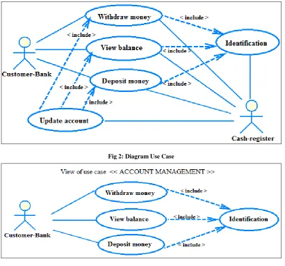
Two main actors in our system are identified (see Figure 2): • The actor Customer-Bank identifies for "Withdraw Money ", for "Deposit Money" or / and for "View the Balance." • The actor Cash-register that supports the operations performed by the customer.
Fig 2: Diagram Use Case
4.2
Elaboration of actions
[image:5.595.307.540.71.304.2]
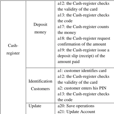
This step consists of cutting and designing use cases in various elementary actions of actors in the system (Table 1) where action is an effect produced by an actor to achieve an objective. Here, the inclusion relation ("includes", Figure 2) expresses the fact that a use case includes a consecutive sequence of actions and it is possible to factor (i.e. find what is common in actions and group ) with other cases of use.
Table 1. Description of use case views of the system BANK
Actor Use Case Decomposition action
Customer-Bank
Withdraw
money
a1: customer identifies itself by his card
a2: customer enters his PIN a3: customer chooses "Cash withdrawal" operation a4: customer specifies the amount to withdraw a5: customer takes money a6: customer takes the card View
(Ckeck)
balance
a1: customer identifies itself by his card
a2: customer enters his PIN a7: customer chooses operation "View balance" a6: customer takes the card
Deposit
money
a1: customer identifies itself by his card
a2: customer enters his PIN a8: customer chooses the operation "Cash deposit" a9: customer deposits money a10: customer validate or not the amount deposited a11: customer takes the deposit slip
a6: customer takes the card
Cash-register
Withdraw
money
a12: the Cash-register checks the validity of the card a13: the Cash-register checks the code
a14: the Cash-register checks the balance
a15: the Cash-register debit the account by the amount requested
View
balance
a12: the Cash-register checks the validity of the card a13: the Cash-register checks the code
a14: the Cash-register control the balance
a16: the Cash-register displays information
Cash-register
Deposit
money
a12: the Cash-register checks the validity of the card a13: the Cash-register checks the code
a17: the Cash-register counts the money
a18: the Cash-register request confirmation of the amount a19: the Cash-register issue a deposit slip (receipt) of the amount paid
Identification
Customers
a1: customer identifies card a12: the Cash-register checks the validity of the card a2: customer enters his PIN a13: the Cash-register checks the code
Update a20: Save operations a21: Update Account
After decomposing use cases in a series of actions, the actions found are factored in parts which will be then sub-components [11].
This factorization of actions use cases concerning CUSTOMER-BANK and the CASH-REGISTER actors of system leads to constitute parts from a list of actions (a1 to a20). The parts produced are:
The customer is the operator, ie d. operations are performed by the customer.
P1: WITHDRAWAL a3, a4, a5 P2: DEPOSIT a8, a9, a10, a11 P3: BALANCE INQUIRY a7
The operator is the cash-register; it supports the execution of operations.
P4: IDENTIFICATION a1, a12, a2, a13 P5: WITHDRAWAL a14, a15
P6: DEPOSIT a17; a18; a19 P7: BALANCE INQUIRY a14, a16 And P8: UPDATE a20; a21
According to this decomposition, it see that P1, P2 and P3 refer to shared parts P5, P6 and P7 whose functionality depends on the actor of the system.
Relationship "include" is a relationship in which a use case (base use case) includes another use case features (inclusion use case). It supports the reuse of functionality in a use case. In Figure 2, "Withdraw money", "View Balance" and "Deposit money" of CUSTOMER-BANK, are base use cases of inclusion use case "Identification" of CASH-REGISTER, according to the "includes" relationship.
"Update Account" of actor CASH-REGISTER is a base use case with respect to inclusion use cases "Withdraw Money", "View Balance" and " Deposit Money" of the CUSTOMER-BANK actor.
And thereafter, the actions corresponding to base use cases are a1, a2, a3, a4, a5, a6, a7, a8, a9, a10, a11, a20, and a21. Similarly, the actions corresponding to the inclusion use case are a12, a13, a14, a15, a16, a17, a18, and a19.
Therefore, the parties WITHDRAWAL, CONSULTATION and DEPOSIT of the view use case ACCOUNT are sources of information to the view use case DISTRIBUTOR.
[image:6.595.96.505.78.269.2]The approach is to associate with each actor (i.e. a use case view) a part or group of parts that meets the needs of the actor (see Figure 5).
Figure 5: Cutting of use case view in parts
4.3
Identification components
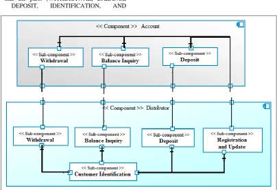
This is a step that aims to associate combinations of parts obtained at the end of the previous step in order to develop the various components and sub-components of the system. Generation model of component design view is carried from the stage "Elaboration of activities “ of the components of the system, so that the parts (WITHDRAWAL, BALANCE INQUIRY, DEPOSIT, IDENTIFICATION, AND
REGISTRATION/UPDATE ) become sub-components of DISTRIBUTOR component and parts (WITHDRAWAL, BALANCE INQUIRY, DEPOSIT) become subcomponents of ACCOUNT component (see Figure 6).
The communication between the sub-components is via ports input / output interconnected to ensure the proper functioning of the system.
Figure 6: Diagram of component of use case view CASH-REGISTER
Identification of interfaces provided / required is based on the actions defined in the step of identifying the components (Table 1), so it is necessary to know first the sub-components, which are sources of information and have strong values.
Firstly, it must know the source sub-components of information and strong values that will provide the interfaces provided.
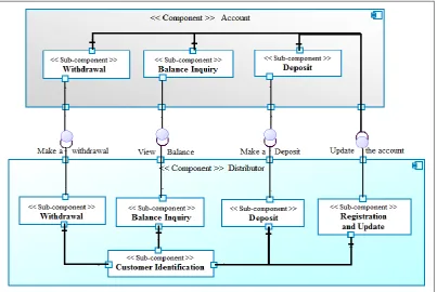
[image:6.595.95.500.380.657.2]Figure 7: Diagram of component of use case view CASH-REGISTER
As for the "REGISTRATION AND UPDATE" part of the view use case DISTRIBUTOR, it becomes a sub-component to having a provided interface for the sub-components of ACCOUNT component.
The sub-component WITHDRAWAL of ACCOUNT component provides an interface provided called "Make a Withdrawal" derived from actions a3 and a14 describing more the role of the interface to WITHDRAWAL sub-component of DISTRIBUTOR component.
For BALANCE INQUIRY sub-components of ACCOUNT component, it offers a provided interface called "View Balance" from action a7 and a15 to BALANCE INQUIRY sub-component of DISTRIBUTOR component. The REGISTRATION AND UPDATE sub-component of DISTRIBUTOR component offers provided interface to the three sub- component of ACCOUNT component as name "Update Account" from actions a19 and a20.
In summary, the "View Balance", "Make a Deposit" and "Make a Withdrawal" are interfaces provided of the ACCOUNT component towards the DISTRIBOTOR component and are interfaces required of the DISTRIBOTOR component towards the ACCOUNT component. As for the interface "Update the account", it is a required interface of the ACCOUNT component towards the DISTRIBUTOR
component and is a provided interface of the DISTRIBUTOR component towards the ACCOUNT component.
In Figure 7, it represents the interfaces provided by a gray disk, and required interfaces are symbolized by a black half circle.
4.4
Assembly components
[image:7.595.98.502.475.745.2]5.
CONCLUSION AND PERSPECTIVES
The software components are interested in problems that are not taken into account until now. They have a particular vision of how to develop softwares; they are processes that provide steps to drive the development.
It is no coincidence that the notion of component provides great interest for the development of complex systems. It presented an engineering approach based on components that is based on the factorization data process with its four stages: identification of the constituents, development activities of the constituents, identification of system components and component assembly.
The use of actions has shown its effectiveness for the identification of sub-components and interfaces in all steps of the proposed approach.
Currently, the research focuses on the complete definition of approach conception of information systems based on components. This type of research should lead to a real and effective method of engineering domain. The objective is to define a method of analysis/conception of components in modeling complex systems.
6.
REFERENCES
[1] Booch.G. 1993. Object-oriented Analysis and Design with Applications (2nd ed. ed.). Redwood City: Benjamin Cummings. ISBN 0-8053-5340-2.
[2] Cheesman.J. and Daniels.J. 2001. UML Components - A Simple process for specifying Compnent-Based software , Addison-wesley.
[3] CORBA. 2014. http://www.omg.org/spec/CORBA/3.3/
[4] D’Souza.D.F. and Wills.A.C. 1998. Objects, Components, and Frameworks with UML - The Catalysis Approach. ADDISON-WESLEY.
[5] B.E. El Asri, M. Nassar, B. Coulette, and A. Kriouile. 2006. "Architecture d'assemblage dynamique de composants multivues dans VUML", ;in Proc. INFORSID, 2006, pp.943-958.
[6] Fabresse.L. 2007. Du découplage à l’assemblage non-anticipé de composants Conception et mise en oeuvre du langage à composants SCL.
[7] Hair. A, Krioule.A, Coulette.B, 2002. Un processus d’analyse et de conception unifié basé sur le concept de
point de vue. Actes de CARI’02, Octobre, Yaoundé, Cameroun.
[8] Jacobson.I. 1992. Object-Oriented Software Engineering: A Use Case Driven Approach. ISBN 0-201-54435-0.
[9] Jacobson.I. Booch.G. and Rumbaugh;J. 1999. The Unified Software Developement Process, Addision-Wesley.
[10] Kruchten P. 1998. The Rational Unified Process: An Introduction.
[11] Kriouile. A. 1995. VBOOM, une méthode orientée objet d'analyse et de conception par points de vue. Université Mohammed V de Rabat.
[12] McIlroy.M.D. 1968. Mass produced software components. In Proceedings, NATO Conference on Software Engineering, éditeurs P. Naur et B. Randell, Garmisch, Germany. [McIlroy, 1968, http://fr.wikipedia.org/wiki/Douglas_McIlroy
[13] Microsoft. 2014. NET Framework Developer Center, http://msdn.microsoft.com/fr-fr/vstudio/aa496123.
[14] Nassar.M. 2005. Analyse/conception par points de vue: le profil VUML. Thèse en Informatique à L’institut National Polytechnique De Toulouse.
[15] OMG. 2014. O.M.G. Home Page, http://www.omg.org,
[16] Renaux.E. 2004. Définition d’une démarche de conception de système a base de composants, Université de Lille 1.
[17] Renaux.E. 2004. Les composants logiques : vers une ingénierie à base de composants. 59655 VILLENEUVE D’ASCQ cedex.
[18] Renaux .E, CARON.O and GEIB.J.M. 2003. The Component Unified Process Project. In SEA’03, page 669-647, Los Anglos USA,.IASTED,ACTA Press.
[19] Rochfeld.A. et Colletti.R. 1983. La Méthode Merise Tome 1 : Principes et outils. Éditions d'Organisation, Paris.
[20] Sun. (2014). E.J.B. HomePage,