Automatic Accident Alert and Safety System using
Embedded GSM Interface
Kajal Nandaniya
I&C DepartmentDDIT, Nadiad
Viraj Choksi
Project ScientistBISAG, Ghandhinagar
Ashish Patel
Assistant professorI&C Department, DDIT, Nadiad
M B Potdar.
Ph.D Project Director BISAG, GandhinagarABSTRACT
The system envisioned is an automatic collision detection and warning system relying on GPS module and a GSM modem. The vehicle to be safeguarded is to be fitted with the system sturdily ensuring good mechanical coupling with the entire chassis. In the case of an accident the system detects it using the fact that the vehicle would be suddenly decelerated in such a condition. An accelerometer continuously monitors the acceleration of the vehicle and will detect decelerations greater than threshold value and send the data to the microcontroller via an ADC. The controller compares this with the threshold set value and immediately sends an SOS message to preset numbers. With this message the controller also transmits the GPS coordinates of the vehicle which it continuously obtains from the GPS module. This system will highly aid the search and rescue of vehicles that have met with an accident.
Keywords
Keywords - Embedded, Microcontroller, Accelerometer sensor, GSM, GPS
1.
INTRODUCTION
Now a day the vehicle accident rate has been increasing day by day, when compared to previous decade the theft rate has been increased by 54% in order to avoid this vehicle accident this system provide security to the vehicles. Main aim of this work is to provide security to the vehicle in very reasonable cost so in this work the basic microcontroller AT89S52 is used for cost effective and also for easy understanding. In this work C programming is used for better accuracy and GPS and GSM modules which helps use to trace the vehicle anywhere on the globe. Here, GPS, user segment and control segment are used to trace the vehicle perfectly and here GSM is used to send the exact location of the vehicle and send alert or relax message to this remote device (mobile phone) [1].
To detect the accident, accelerometer sensor used. So, when accident happens, this sensor will be active. And the information sends to microcontroller. At the same time, GPS and GSM modem will also active which are interfaced to the same microcontroller. Through GPS the exact latitude and longitude of the accident location is obtained. And through GSM modem the same data send to the contacts which are stored in the database. So with this system, information is send to the Police Stations, friends etc. and also decrease the total action time and save the lives in emergencies.
2.
SYSTEM BLOCK DIAGRAM
Fig 1: System Block Diagram
Here in this system, AT89S52 is used as main microcontroller. This system is made for the Accident alert system. Here, the whole system is to be implemented in the vehicle itself. So, when the accident happens, due to vibrations, the accelerometer sensor gets active. It measures the certain intensity of shocks and vibrations. So it is detected to microcontroller through ADC0804. Here ADC0804 required, which is interface between MMA7361L and microcontroller AT89S52 because output of the accelerometer sensor is analog and to interface with microcontroller, it is to be converted in to the digital.
3.
CIRCUIT DIAGRAM
Fig 2: circuit diagram
In this system MMA7361L Accelerometer sensor is used for measure intensity of shock and vibration which gives output voltage to the microcontroller AT89S52 via ADC0804. ADC0804 is used for converting analog voltage from accelerometer sensor to digital voltage which is given to the microcontroller through Port 1 and Port 3 of microcontroller which is configured as an input port.
GSM modem and GPS module are connected with transmitter and receiver pins of microcontroller respectively. Longitude and latitude information are continuously received in microcontroller through GPS module. In microcontroller one threshold value is set for deceleration if vehicle is suddenly decelerate and deceleration is greater than threshold value then it is detect by microcontroller and at that instant longitude and latitude information are fetch and display on LCD(16*2). This information is transferred through Port 0 and Port 2 of microcontroller. Port 0 is connected to the data lines of LCD there are a pull up resistor is also connected with Port 0 because it is an open collector Port. Port 2 is connected with handshaking lines of LCD. At the same time when accident is detected or deceleration is greater than threshold value. At that time “accident happened, car number, owner Name” this type of message will be send to the list of contacts which are preadded into list of contacts which are saved in database of system.
This action is done by GSM modem which is SIM 300 used for sending text messages. Information of accident detected, longitude and latitude information are transmitted to the GSM modem through transmitting pin of microcontroller. There is an addition of one panic switch which is used when deceleration is greater than threshold value but if there is no any injury happened or no any danger to lives then panic switch is in use. After pressing panic switch another relative message like “Don’t worry, we are safe” will be send to the same contacts which are used for the previous scenario.
The vehicle to be safeguarded is to be fitted with the system sturdily ensuring good mechanical coupling with entire chassis. Normally the system would draw power from the vehicles battery which would ideally be 12V dc. The controller and its associated circuitry which require 5V dc are supplied from a 7805 three terminal onboard regulator. The accelerometer is supplied with 3.6 V by dropping the regulator voltage with two forward biased 1N4007 diodes.
4.
HARDWARE DESIGN
4.1. The Controlling Unit
.The flash chip takes only two to three seconds to be programmed [4].
The onboard flash memory guarantees an endurance of 1000 erase/program cycles. The version s52 is different from the c52 by the fact that it has a programming voltage of 5V as compared to 12V of that of the c51/52 devices. This controller is also in-system programmable thus reducing the development time even further. The chip has 316 bit timers/ counters and 8 interrupt sources [4].
The maximum frequency supported by the chip is 33MHz [4]. Here the microcontroller has been connected in a standard fashion. The clock crystal of 12MHz has been connected between pins 18 and 19 which are the osc 1 and osc 2 pins of the controller. Further pins 18 and 19 are bypassed to ground via two 22pf capacitors which ensure that the internal oscillator is self starting. A power on reset network is also connected with the controller, in the form of a 10uF capacitor connected to the Vcc supply from pin 9 which is the reset pin of the controller. A 10 k resistor is grounded from the same pin. When the power to the circuit is switched on, the capacitor which initially has zero charge on it will take a high charging current. This charging current will flow to ground via the resistor thus generating a positive going short pulse across it. The time duration of this pulse is equal to the time constant of the RC network. Apart from this the system CPU can also be manually reset with the help of the reset switch that has been connected in parallel to the 10uF capacitor.
Port 1 and Port 3 of the controller has been configured as the input port to which the output of the ADC is connected. The LCD has been connected to Port 0 and 3 lines of Port 2. The UART of the microcontroller have been divided between the GSM modem and GPS module. The RxD of the controller is connected to the output of the GPS module and the TxD of the controller has been connected to the data in of the GSM modem.
4.2. The Information Detection Module
The accelerometer that is used in this system is the MMA7361L from Freescale semiconductors. This sensor is a 3 axis analog output accelerometer. The device consists of a surface micro machined capacitive sensing cell (g-cell) and a signal conditioning ASIC contained in a single package. The sensing element is sealed hermetically at the wafer level using a bulk micro-machined cap wafer. The g-cell is a mechanical structure formed from semiconductor materials (polysilicon) using semiconductor processes (masking and etching). It can be modeled as a set of beams attached to a movable central mass that move between fixed beams. The movable beams can be deflected from their rest position by subjecting the system to acceleration. As the beams attached to the central mass move, the distance from them to the fixed beams on one side will increase by the same amount that the distance to the fixed beams on the other side decreases. The change in distance is a measure of acceleration. The sensor operates at very low voltages (2.2V to 3.6V). During active mode the sensor draws about 400µA and when in sleep mode it draws only 2µA current [6].
The g range is selectable between 1.5g and 6g. The 3 axis accelerometer contains an onboard single-pole switched capacitor filter. Because the filter is realized using switched capacitor techniques, there is no requirement for external passive components (resistors and capacitors) to set the cut-off frequency. Here the output along only one axis has been utilized (the axis along which the car is moving forward). The analog output of the accelerometer is fed to the input of the ADC.
4.3. GPS Location Module
The GPS module that this system has used is from manufactured by iWave. The module has a 20 channel receiver with a tracking sensitivity of -159dBm and an accuracy of 10m. This module has a startup first acquisition time of 2 seconds during normal temperatures and up to about 40 seconds under extreme cold conditions. Maximum working altitude for the module is 18000m and max. linear working speed is 514 m/sec. The output protocol is NMEA (National Marine Electronics Association) at data speeds of 4800 or 9600 bauds. The module works on 3.3Vdc which is provided from a regulator on board [5].
4.4. Message Transmission Modem
The modem used here is SIM300 readymade GSM module. This module accepts a single simcard and can send and receive messages (text messages) [3].
It can be controlled by sending AT commands from any general purpose microcontroller UART. Here it has been connected to the microcontroller TxD and RxD pins. It is powered by +5V dc which is obtained from the motherboard.
This modem manufactured by Simcom is a tri-band GSM modem which supports EGSM 900, DCS 1800 and PCS 1900 GSM networks. The band can be set by AT commands but default band is EGSM 900 and DCS 1800 [3].
5.
FLOW DIAGRAM
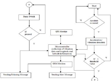
Fig 3: Flow Diagram
The system is implemented in vehicles. The vehicles are monitored continuously through microcontroller. Hence, when accident is detected, accelerometer sensor gets activated, these sensor have threshold values depend on different vibration intensities.
If the vibration intensity is more than the specific threshold value, the accelerometer sensor activated at the same time, GPS module and GSM modem which are interfaced to microcontroller are also activated. So, through GPS module, the exact location of latitude & longitude of the location can be identified and GSM modem sends the messages as per condition.
6.
COCLUSION
With this system, an Embedded System is designed which can be most useful for Accidents. It’s a low cost, Power efficient system by which the action time can be minimized and exact location of an accident can also be defined with GPS service and also the information regarding accident can be sent to particular contact numbers e.g., Police stations, Doctors etc..Because of the flexibility of embedded system, this system is very much compatible to any kind of vehicles. Over all this system is very much affordable to a common man and this can be easily implemented.
7.
FUTURE SCOPE
This system can be extended by using ARM processors and Arduino controllers instead of microcontroller for very fast operation of processors. And also the cameras can be interfaced with this system to see the exact scene of an accident. And also the system can be design which automatically shutoff vehicle engine while accident occurs.
8.
ACKNOWLEDGMENT
9.
REFERENCES
[1] M Rajendra Prasad, P Aswani Kumar," An Automated Traffic Accident Detection and Alarm Device" in International Journal of Technological Exploration and Learning (IJTEL), Volume 1 Issue 1 (August 2012).
[2] C.Vidya Lakshmi, J.R.Balakrishnan,"Automatic Accident Detection Via Embedded GSM message interface with Sensor Technology " in International Journal of Scientific and Research Publications Volume 2, Issue 4, April 2012.
[3] “GSM SIM 300 Module”, Internet: www.positronindia.in, Product URL: http://positronindia.in/PT0006.aspx.
[4] “Microcontroller (Atmel AT89S52 Data Sheet)”, Internet: http://www.atmel.com.
[5] “GPS Module”, Internet: www.iwavesystems.com.
[6] “Accelerometer Sensor (MMA7361L)”, Internet: www.pololu.com.
[7] Jules White, Chris Thompson, Hamilton Turner, Brian Dougherty, and Douglas C.Schmidt, "WreckWatch: Automatic Traffic Accident Detection and Notification with Smartphones" in Journal of Mobile Networks.