A Review of Packet Marking IP Traceback
Schemes
Ashwani Parashar
Scientific Officer
National Informatics Center, Department of Information Technology, Govt. of
India
Ramaswami Radhakrishnan,
PhD. Head of Department, Computer Science EngineeringABES Engineering College, Ghaziabad UttarPradesh, India
ABSTRACT
Today, Internet has become the primary source of communication in networks. The attack on its infrastructure poses a great challenge in its expansion. Distributed Denial of Service attack is a serious security threat encountered during the past decade. The goal of the attacker is to spoof the source of IP address to hide its source. Various IP traceback schemes such as Probabilistic Packet Marking, Deterministic Packet marking, TTL base Packet Marking and Hash base IP traceback schemes are proposed to trace the source of the attacker. This paper summarizes the different IP traceback techniques and compares their effectiveness in countering DDoS attack.
General Terms
IP tracebackKeywords
Traceback, DDoS, PPM, DPM
1. INTRODUCTION
DDoS attack is a major source of Cyber attack [1]. The attacker tries to hide its identification by spoofing the IP Address. Current IP traceback mechanisms can be mainly classified into four categories [2]. These are packet marking, Debugging, Link Testing and Messaging. Packet marking mechanisms mark the identification of the routers in the IP packets. Marking mechanism such as Probabilistic Packet Marking Mechanism (PPM) and Deterministic Packet Marking (DPM) mechanism rely on packet marking for identification of attackers. In PPM, all routers mark the packet using some probability. The victim reconstructs the path back to the source using the bit encoding by each routers. PPM mechanism can also uses TTL value in the packet to identify the source of malicious packets. DPM marks the packet with fixed probability. It uses the identification of ingress routers while marking the packets. SIT(Speedy IP traceback).uses MAC address for marking in the IP packet [3]. This is based on the assumption that the MAC address may not be spoofed by the user since it changes from one hop to other. So, MAC address of source is marked in the packet which can later easily traced. But, MAC address copying is violation of privacy. It is also subject to spoofing. One marking mechanism uses checksum to encode the IP Address and Traffic filtering mechanism at ingress router to drop the spoof packets at ingress interface [4].
Link testing methods include input debugging [5] and controlled flooding methods [6]. The main idea is to start from the victim to locate the attacker from upstream links by testing the possible routes and then finding the attack path. This technique has limitations when there are branching in the network as it increases the overloading of the network. When the Network Traffic is quite heavy, this technique is not
feasible to use. If the victim is receiving significant attack traffic, then this technique is less effective.
Another traceback technique is Messaging. Bellovin [7] proposed ICMP messages to traceback the source of attacker. ICMP messages are sent to find the source of forged packets. But, the limitation of this technique is that generally routers do not allow to exchange of ICMP messages. Also, when the network traffic is very high, this generates additional traffic. In section 2 PPM technique is discussed. Section 3 describes DPM. Section 4 provides information about TTL base packet Marking Techniques. Challenges and conclusions are outlined in section 5.
2. PPM
The design of any IP traceback process relies on the assumptions [8] which are as follows:-
The attacker can send many packets.
The attacker can spoof the packets.
The attacker may be aware that they are being traced
The network infrastructure has limited memory and storage capacities.
The CPU available has also limited processing capability.
Multiple ISPs may not support each other during the traceback process.
The attackers can send multiple packets. Hence the marking mechanism should be such that it should be evenly spread over normal and malicious traffic. It should try to cover malicious packets as much as possible. The attackers can spoof the packets and the attacker may also be aware that they are being traced. Hence the IP mechanism must provide mechanism of randomness in marking so as to thwart the attacker from discovering the mechanism of marking. The network infrastructure has limited memory and storage capabilities. Hence the mechanism should be such that storage of the marking details in IP packet should be limited so as not to obstruct the normal flow of the traffic. The CPU has limited memory. Hence, the marking by routers in the packets should be performed by control plane. The forwarding plane should forward the packets so that the normal traffic is not obstructed.
field is incremented. Here router is using probability and randomness for marking the packets. Hence, by using this technique, the edges between the routers are encoded which will be used for path reconstruction during IP traceback mechanism.
R1 R2
R4
R7 A3
R3
R6 A2
R5 A1
[image:2.595.347.501.75.245.2]V
Fig 1: Network as seen from the victim of an attack, V. Routers are represented by R, and potential attackers by
A. The dotted line represents a particular attack path between an attacker and the victim.
The victim uses edge samples to create the graph as shown in fig 1. In PPM, there is less probability of marking of packets by farthest routers. The expectancy to receive the packet in time is bounded by the equation 1/(1-p)d-1 where p is the probability and ‘d’ is the number of hops away from the victim.
A modified PPM marking technique was designed which uses the XOR of the two neighbours for encoding the marking information in the packet (fig. 2).
Routers in Path
a
b
c
d
Marked Packets
a b
b c
c d c d
c b c
a b
b a
d
Path Reconstruction at Victim
Recon stucte
d Pat h
[image:2.595.69.264.138.382.2]
Fig 2: Edge data can be communicated in half the space by sending the XOR of the two nodes (i.e., router IP addresses) making up an edge, rather than sending each node separately. Over time the victim receives the messages
d, c
d, b
c, and a
b. By XORing these messages together, the original path can be reconstructed.Address Hash (Address)
Bit Interleave
Send K fragments into Network
0 K-1
Fig 3: Each router calculates a uniform hash of its IP address using a well-known function. This hash is interleaved with the original IP address (the original address on odd bits, the hash on even bits). The resulting
bits are then broken into k fragments, which the router selects among randomly when marking a packet.
Another technique which considers interleaving of hashing of IP address with normal IP address(fig3). This is further broken into fragments which the routers select randomly among the packets to mark in IP Packet. The main drawback of this scheme is that each and every router is involved in marking which puts heavy overload on the network. Number of false positives will also increase as intermediate routers are also involved in encoding their edge in the path. Also, as per this scheme, farther the router from the victim, lesser is the probability that the packets are marked. It marks the packet with fixed probability of 1/d. Another technique named as Adjusted Probabilistic Packet Marking [9] improves the probability to mark the packet. This marking scheme proposes to mark the packet with probability p=1/(c+1-dv) where dv
is the distance of the router to the victim and ‘c’ is the constant. This scheme decreases the number of unmarked packets.
SPIE [10] (Source Path Isolation Engine) is another traceback technique based on logging. In this technique, log based mechanism is installed at the router by computing and storing 32 bit packet digest. If any packet is found to be malicious, the query is dispatched to SPIE which in turn queries router for packet digest of the relevant period. SPIE then builds the graph of router visited by the packet.
Version Header Length
Type of
Service Total Length
Identification D
F M
F
Fragment Offset
TTL Protocol Checksum
Source Address
Destination Address Options
[image:2.595.55.274.548.687.2]Payload
[image:2.595.308.547.592.757.2]In this technique, the invariant field in the IP packets is passed to the input digest function to produce the digest. The variant fields like TTL and checksum which are subject to change at every hop is not included in the digest function to produce the digest (fig.4). Option field is also rewritable by routers at various intervals. The SPIE masks these variant fields so as to have same digest at all hops. SPIE must also handle the situation when header is changed due to the transformation of packet (tunneling). SPIE architecture (fig.5) consists of DGAs (Data Generation Agent) installed at each router. These DGAs collects data at each router and hierarchical set of SPIE collection and reduction agent (SCARs) that ask these DGAs if they have seen packet in question. The DGA produces the packet digests and store the digests in bit mapped digest tables.
STM
Router
Router Router
Router
Router Router Router
Router
Router Router
DGA
DGA
DGA
SCAR
[image:3.595.318.537.75.281.2]ISP’s Network
Fig 5: SPIE Architecture consisting of Data Generation Agents (DGAs), SPIE collection and reduction agent
(SCARs) and SPIE Traceback Manager (SPM)
The rest of SPIE system is concerned with the query mechanism, attack graph generation and system security. These digests are stored in bloom filter [10]. This mechanism will not generate false negatives because at each router identification is encoded. False positives may be generated because the encoding may be due to hashing of other field. The false positives may be limited by SPIE.
SPIE mechanism requires separate hardware for Data storage. It increases additional overhead to the existing resources.
3. DPM
DPM [11] takes 17 bits of IP Packet field (16 bit ID field and 1 bit of Reserve flag) to mark the packets and these marks remain unchanged for as long as the packet traverses the network. (Fig. 7) The mark is done by ingress router closer to the source of attack. Hence it ensures that egress router does not overwrite the mark. Hence, the scheme makes a distinction between inbound and outbound packets. The marking of the packets is done deterministically. If the attacker tries to spoof the source address of the packet, this will be overwritten with correct marks by the very first router the packet traverses. The coding in the ID field assumes that there are almost no IP fragments in the internet. This assumption was made in [12] and is supported by empirical traffic analysis that less than 0.5% of packets are fragmented [13]. The discussion about this is made at the end of the section. In this scheme IP address of 32 bits is fragmented into two parts of 16 bits each. The one bit flag will indicate whether the fragment is first or second. The advantages of the DPM is manifold
It is simple
It is scalable
It has no inherent security flaws
A
A
BackBone Routers
DPM Enable d Edge Routers
V A
A
DPM10.128.68.1 164.100.57.2
164.100.53.3
164.100.57.1
164.100.
[image:3.595.318.540.122.585.2]53.1
Fig 6: Deterministic Packet Marking
Original Datagram
Data
Data Segment 4
Data Segment 3
Data Segment 2
Data Segment
1 IP Header
IP Header
Data Segment 4
IP Header
Data Segment 3
IP Header
Data Segment 2
IP Header
IP Header Data Segment
1
Fragment 4 Fragment 3 Fragment 2 Fragment 1
Fragment Series
Fig 7: IP Fragementation
[image:3.595.59.271.225.376.2]fragmentation of packet will be done. Finally the offset field of the IP header is set to the portion of the data in the fragment w.r.t. the beginning of the data in the original datagram. The offset is measured in 8 bytes. For successful reassembly, the destination has to acquire all the fragments of the original datagram. Since DPM uses identification field and marking the identification field with different marking will lead to reassembly error. Fragmentation can happen upstream or downstream from the point of marking. Upstream fragmentation is known to the Deterministic Packet Marking (DPM) enabled interface. The DPM enabled interface can identify a packet to be fragmented by examining its MF and offset. DPM can employ a different strategy for marking these packets. Downstream fragmentation is unknown to DPM and it causes few problems for reassembly. The router which is going to fragment the IP packet will simply insert the ID field in all the fragments. At the destination, the assembly will be successful since ID field will contain the same contents for all the fragmentation of IP Packets.
Upstream fragmentation will cause more problems for DPM enabled interface. Since basic DPM does not distinguish between fragments and each ID field of the fragments will contain marking, will cause the reassembly error at the receiving host.
In fragment persisted DPM, the fragment of a single IP Packets will be marked same in their ID field. The information has to be stored in a table at the DPM enabled interface and checked every time a new fragment arrives to identify fragments to the same original datagram. DPM should check if the tuple of the four fields utilized by reassembly function (SA, DA, P, and ID) is same as any other it marked with the maximum reassembly timeout of 120 seconds.
Since the attacker can send many fragments to perform DDoS attacks, hence to remedy this situation, simple modification to persistent DPM could be made. As per study in [14], it was determined that the number of fragment of the IP Datagram does not exceed the value of 44. Hence a counter could be initialized in the algorithm which will keep trace for the value of 44. Hence, it will not accept further fragment of packet over this value.
Flexible Deterministic Packet marking [15] is another marking technique in the family of IP traceback techniques. The novel characteristic of FPDM is its flexibility. First, it can adjust the length of marking field according to network protocols deployed (flexible marking strategy) and second it can also adaptively change its marking rate according to the load of the participating router by a flexible flow marking scheme. The mark recognition step is the reverse process of encoding. By reading control fields in the IP Packet, the length of the mark and which fields in the IP header store the mark can be recognized. If the RF is Zero, the mark length is 24 (Both ID and TOS are deployed). If the RF is 1, according to different protocols of TOS used, the mark length will be 16 or 19. Flow based marking scheme marks the packet according to the flow. A flow table is maintained (Fig. 8)
Flow Table T
Flow 1 Destination IP
Address 1
Number of packet in flow 1;npkt1
Flow 2 Destination IP
Address 2
Number of packet in flow 2;npkt2
--- --- ---
--- --- ---
Flow n Destination IP
Address n
Number of packet in flow n; npktn
Calculate npkti{i {1,n}) in Q
Enqueue
Dequeue Incoming
[image:4.595.319.541.77.142.2] [image:4.595.317.540.400.522.2]Packet
...
.
Queue length of Q
Fig 8: Dynamic flow table T and FIFO queue Q in FDPM flow-based marking scheme.
For each DA, there are two load thresholds Lmax and Lmin for
the traceback router. Lmax is the threshold that control whole
packet marking process, which means that router will not mark the packet if the load exceed the threshold. Congestion control scheme can be turned on to guarantee best effort services for the router. The load threshold Lmin means that if
the load exceeds this value, the marking will be continue but with reduce marking load. If the load stays below Lmin, then
the router will just mark all the packets because router can process all the packets without performance penalty.
Logging and Deterministic Packet Marking algorithm [16] (LDPM) traces the special “edge” path which consists of Rs and Rd (fig. 9)instead of entire path in PPM or a single point in DPM only. The Rs identity information is recorded into every packet of Rs and marking information cannot be overwritten by other routers. When the packet reaches router ASd , the relevant Rd logs the packet information in the local database. The marking and logging the packets can also be done alternatively.
Rs
Transit AS
Attack Path Rs to Rd
Rd
V
A Ingress Interior
Router Border Router Connecting ASs Victim
Attacker
ASd ASs
Fig 9 : Principal of LDPM Technique
4. TTL BASE PACKET MARKING
TTL base Packet Marking [17] in which packet is marked with probability inversely proportional to the distance travelled by the packets so far. Therefore, packets that have to traverse longer distance are marked with higher probability comparing to those that have to traverse shorter distances. This ensures that packet is marked by intermediate routers with higher probability. This enables the effectiveness of tracing spoofed packet to source.In the algorithm where tp is the maximum remaining distance,
if the TTL value of packet is greater than tp, then the packet is
marked with highest probability. This scheme can be incorporated in PPM based techniques.
The main drawback of these schemes is that these mechanisms are still marking the spoofed packets which are increased due to DDoS attacks. Hence, the overhead on the router is increased manifold due to increase in malicious traffic and marking of packets by router.
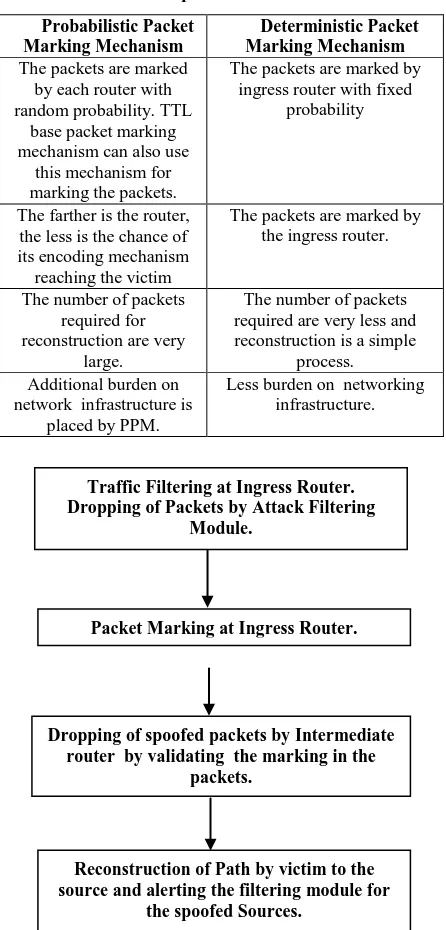
[image:5.595.56.279.258.723.2]Scope of future work lies in making the marking mechanism more effective by introducing Packet Filter module along with DPM so that overhead of router in marking the spoofed packets is reduced to minimum. The DPM mechanism discussed in this paper involves the marking of packets by ingress router. This mechanism can also be improved by involving intermediate routers in filtering the spoofed packets by validating the marking in the IP packet so that the malicious traffic reaching the host is reduced to minimum. The victim can reconstruct the path of spoof packets and alert the filtering module for the source of spoof packet. (fig 10)
Table 1. A comparison of PPM vs. DPM
Probabilistic Packet Marking Mechanism
Deterministic Packet Marking Mechanism The packets are marked
by each router with random probability. TTL
base packet marking mechanism can also use
this mechanism for marking the packets.
The packets are marked by ingress router with fixed
probability
The farther is the router, the less is the chance of its encoding mechanism reaching the victim
The packets are marked by the ingress router.
The number of packets required for reconstruction are very
large.
The number of packets required are very less and reconstruction is a simple
process. Additional burden on
network infrastructure is placed by PPM.
Less burden on networking infrastructure.
FIG.10: PROPOSED IPTRACEBACK MECHANISM
7. REFERENCES
[1] S. Savage, D. Wetherall, A. Karlin, and T. Anderson, “Network support for IP traceback,”IEEE/ACM Trans. Networking, vol. 9, pp. 226–237, June 2001.
[2] M. Alenezi, M.J.Reed, “IP traceback methodologies”, Proceedings of IEEE conference in Computer Science and Electronic Engineering Conference (CEEC), 2011. [3] Vaarun Vijairaghavan, Darshak Shah and Pallavi Galgali, Amit Shah and Nikhil Shah, Venkatesh Srinivasan, Lokesh Bhatia, “Marking Technique to Isolate Boundary Router and Attacker”, IEEE Computer Society, 2007. [4] M.Vijayalakshmi,Dr.S.Mercy Shalinie, A.Arun Pragash, “IP traceback system for network and application layer attacks”, Proceedings of IEEE Conference on Recent Trends in Information Technology (ICRTIT),2012.
[5] R. Stone, "CenterTrack: An IP Overlay Network for Tracking DoS Floods", Proceeding of ACM SSYM'00 Proceedings of the 9th conference on USENIX Security Symposium - Volume 9, 2000.
[6] H. Burch and B. Cheswick, "Tracing Anonymous Packets to their Approximate Source", Proc. of the 14th Systems Administration Conference (LISA 2000). [7] S. M. Bellovin. ICMP traceback messages. Internet draft: draft-bellovin-itrace-00.txt, Mar. 2000.
[8] Alex C. Snoeren, Craig Partridge, Christine E. Jones, Fabrice Tchakountio, Beverly Schwartz, Stephen T. Kent, Timothy Strayer, “Single-Packet IP Traceback”, IEEE/ACM Transactions On Networking, Vol. 10, No. 6, December 2002.
[9] Bilal Rizvi and Emmanuel Femandez-Gaucherand, “Analysis of Adjusted Probabilistic Packet Marking” IEEE IPOM 2003.
[10] Hosoi Takurou, Kanta Matsuura, Hideki Hnai “IP Traceback by Packet Marking Method with Bloom Filters”,Security Technology, 2007, 41st Annual IEEE International Carnahan Conference, October 2007.
[11 ] Andrey Belenky and Nirwan Ansari, “IP Traceback With Deterministic Packet Marking”, IEEE Communications Letters, Vol. 7, No. 4, April 2003.
[12] C. Shannon, D. Moore, and K. Claffy, “Characteristics of fragmented IP traffic on internet links,” Proceeding
IMW '01 Proceedings of the 1st ACM SIGCOMM Workshop on Internet Measurement, Pages 83-97,2001.
[13] Andrey Belenky and Nirwan Ansari, “Accommodating Fragmentation in Deterministic Packet Marking for IP Traceback”, IEEE GLOBECOM 2003.
[14] C. Shannon, D. Moore, and K. C. Claffy, “Beyond folklore: observations on fragmented traffic,” IEEE/ACM Trans. Networking, vol. 10, no. 6, pp. 709–720, Dec. 2002.
Traffic Filtering at Ingress Router. Dropping of Packets by Attack Filtering
Module.
Dropping of spoofed packets by Intermediate router by validating the marking in the
packets.
Packet Marking at Ingress Router.
Reconstruction of Path by victim to the source and alerting the filtering module for
[15] Yang Xiang, Wanlei Zhou, and Minyi Guo, “Flexible Deterministic Packet Marking: An IP Traceback System to Find the Real Source of Attacks”. IEEE Transactions on Parallel And Distributed Systems, Vol. 20, No. 4, April 2009.