Thesis by
Andrew
v.
Haeff.In Partial Fulfillment of the Requirements for the
Degree of
Doctor of Philosophy
California Institute of Technology Pasadena, California.
Contents.
1. Summary. 2.Introduction.
3. Effect of the change of the position of electrodes with respect to the voltage wave.
{a) • Description of the apparatus.
(b). Dependence of the amplitude of oscillations upon the
3
7
position of the electrodes with respect to the voltage wave 9 (c). Dependence of the required minimum grid current
upon the position of electrodes. 13
(d). Dependence of the minimum grid current upon the v1avelength. 16 (e). Effect of the dissyrmnetry of the grid and plate circuits. 16 4. Analysis of the experimental results. 20 (a). Distribution of standing waves along the wires. 20 (b). Sffect of the grid to plate capacitance on the natural
frequency of the oscillating circuit. 22 (c). Effect of lumped inductance in the Lecher system. 32 (d). Effect of' the distributed inductance and capacitance. 33
5. Wavelength measurements. 43
6. Energy measurements.
(a). Plate current. 47
(b). Thernocouple method. 49
(c). Absolute value of energy output. 51
7. Dependence of energy output upon the emission current.
(a). Limits of maximum energ<J output. 54 (b). Experience with water cooled grids. 57 (c). 1iinimum Vla.Velength as a function of tube constants. 57 8. Conditions for maximum energy out_,ut. 60
1. SUlv'.'.MARY.
The performance of three electrode tubes operating on the Barkhausen principle has been studied. Several tubes of different design have been constructed and tested. One particular desien in which two extra leads >vere brought out from the grid and the plate, proved to be especially advantageous, because its :nini~·1um grid current was small, and the wavelength could be varied continuously throughout the region in which the tube produced oscillations. liormal vraves and v;a.ves of the hicher orders could be produce·d.
The effect of changing the position of electrodes with respect to the standing voltage wave was studied. It was found that tubes oscillate more easily if the electrodes are placed in the loop of the voltage wave. This study was made possible by the design of a special tube and the use of a special circuit.
'l'he de_:iendence of the minimu.'!l grid current upon the v.ravelength has been studied and it was found., that t:.ie t!leoretical relation
k .
lg
=
.A3 is only ap1,roximate: the coefficient "k" increases as the wavelength decreases.The variation of the energy out9ut vnth the e~ission current was studied and it was found, that the maximum energy out1mt is / obtained ~1en the emission current reaches its static saturation
(6)
2. Il?l'RODUC'.;:'I01'I.
Jince the cliscovery by Barkhausen and Kurz in 1920 (Ref.l) of oscillations produced by a three electrode tube in v~1ich the grid has high positive potential, a considerable amount of' work
on the Barkhausen effect has been done by investigators in Germany, Russia, France and in this country. ,_._,_ very com:;:-Jlete outline of the work done pp to 1930 was published by H.E.Hollmann (Ref.2). This article contains also a very complete list of references.
To make further discussion clearer, tho essential features of the Barkhausen oscillator will be considered here.
Tho funda.-inental circuit is represented in Fig. l. The grid is connected to the positive terminal of a
D
.c.
generator or battery.p
6
F L,,.-I,.
- 4
Fzj
.
I.
The l)late is held at zero (negative end of the fila::i.ent) or neto,utive
approximately to the frequency of electronic oscillations around the grid (Ref.l). This rule was later extended and modified {Ref.3,4) and can be stated as follows: The rnaxirmh!n energy output is obtained when the natural frequency of the oscillating circuit corresponds to the electronic frequency or its multiple. \!hen the frequency is equal to the electronic frequency, the waves are called normal waves;
when the frequency is some multiple of the electronic frequency, the waves are called high order waves (1st order, 2nd order, etc.) .
The experiments of Kroebel (Ref.5) demonstrated that a consider-able increase in the output was produced if the plate was made negative.
~...,aximum energy was obtained when the plate current was reduced to zero. Gill and i .. orell {Ref.6) were the first to observe the dependence of frequency upon the tuning of the external circuit. The so called "pure" Barl<.hausen oscillations, the frequency of which does not depend u1)on the tuning of the circuit, were later found to be produced only
in exceptional cases. I t is thow:;:ht that "pure" B-K oscillations occur only if there is a sharply tuned circuit inside the tube, wnich is formed by the electrodes and the leads inside the tube. During the present investigation in no case "pure" B-K oscillations were observed.
'.i:he effect of symmetry in the arrangement of electrodes was studied by ..:,.. '.Jainberg {Ref. 7), w110 has shovm that with tu.bes havine the fila..'11ent or the grid displaced from the position concentric with the plate, no waves of higher orders could be obtained, and that in
( 5)
The exiJerimental study of Barkhausen oscillators was undertaken
with the purpose of fincling means of increasing the energy output in the shorter wave region. Early in the course of investigation it was observed that the capacitance between the electrodes and the wires forming the oscillati1-ig circuit had a consiclerable influence upon the oreratio\ of the tube. The distribution of standing waves along the oscillating circuit was then studied and. it was found that the smaller the ratio of the capacitance between the electrodes to the capacitance per unit length of the oscillating circuit, the easier it is to produce oscillations. To be able to displace the electrodes with res:pect to trie standing wave \'Ii thout cletuning the
circuit, a S}Jecial tube was constructed. The results obtained with this tube will be described in the next paragraph.
Since the principle of operation of the Barld1ausen oscillator
differs radically from that of ordinary oscillators, special tubes were constructed. Part of the work i.ms been done with tubes connected. _permanentl;/ to the evacuating system, consisting of a fore pump and a two stae;e mercury diffusion pump. The pressure was measured by
means of a l.~acLeod gauge. The pressure of 10-4 to l0-5 rrnn.Hg. was usually maintained, between which limits the operation of the tube was not affected by changes in pressure (Ref.8). The tubes \'1ere made so that they could be easily opened for replacing the filo.ment or for changing and adjusting: the electrodes. Several tubes were made wnich after a thorougi1 baking and heating of electrodes were completely
Only cylindrical electrodes were used, the filament and
the grid being placed concentrically with the plate. P!llre tungsten
fils.ments were used. Grids were made of tungsten wire wound in tne form of a spiral. Tungsten was used for grids, because the heat produced by the electronic bombardment is sufficient to melt metals with lower melting point {grids made of nickel melted
rea4ily even at low loading).
A 500-volt D.C. generator supplied the positive volta[e
to the grid. The voltage was varied by means of a potentiometer.
A 45-volt 11B11 battery was used for negative bias on the plate. A 6-volt storage battery was used for heating the filament.
The oscillating circuit usually consisted of a Lecher wire system on which standing waves were formed. The reflecting
condenser bridges were so designed that their natural frequency was considerably above the frequency of the circuit (Ref.9).
The methods used for measuring the wavelength and the
3. Effect of the change of the position of electrodes with
respect to the voltage wave.
(a). Description of ap-oaratus.
( 7)
Fig.2 and Fig.3 respectively show the general view of the
apparatus and the construction of the tube. Fig.4 represents a
schematic diagrfu~ of the circuit.
As can be seen from Figs. 3 and 4, connections to the plate
and the grid are brought out at both ends of the tube, and are
joined directly to the two oscillating circuits L1 and L2 • The
filament leads are bent at right angle to the oscillating circuit
Fzj.3.
c;
( 9)
and are connected directly to the chokes placed close to the tube.
The Lecher system formed by the two circuits· L1 and L2 , is short
circuited at the two ends by means of two condenser bridges 01 and
02. The grid and plate supply voltages (D.C.) are delivered to
the circuit fhrough R.F. chokes and the connections are made at
the ends of the Lecher wires 11 beyond the bridge
c
1 , where nostanding waves are present.
b). Dependence of the amplitude of oscillations upon the position
of electrodes with respect to the standing wave.
The following effect has been observed. With the voltage
and the grid current constant and the bridges
o
1 andc
2 moved in
the s~~e direction along the wires so that their separation remained
constant and the natural frequency of the circuit unchanged, the
plate current was found to depend upon the position of the bridges.
The constancy of frequency was checked by means of an auxiliary
Lecher wire system used for measuring the wavelength (see p.43).
The results are shown on p.10. On the diagram the plate current
Ip is plotted vertically, and the abscissar· represents the position
of the middle of the oscillating circuit. The center line of electrodes
is marked by a dotted line 63 cm. from an arbitrary zero.
A marked decrease of the plate current occurs when the center
line of the circuit is displaced from the center line of the electrodes.
In other words, the plate current decreases when the A.O. voltage
across the electrodes is less than the maximum A.O. voltage in the
(11)
of the electronic space charge which cause the tube to oscillate,
are produced by the A.O. voltages between the grid and plate. Thus,
the conditions for oscillations are most favourable when the electrodes
are placed in the loop· of the voltage wave.
The same effect was observed for waves of different orders and
for different wavelengths. For shorter waves, as for example for30cm.,
the sharpness of the peak is very marked, and shows not only the
importance of proper tuning of the circuit but also the necessity
of placing the electrodes in the loop of the voltage wave. The method
of doing this, as described above, using a special tube, is simple
and effective, and of particular importance for short wavelengths.
The curves on p.12 show the change of the plate current as
a function of the displacement of electrodes with respect to the
position of the loop of the voltage wave expressed in percent of
wavelength. It should be noted, however, that the shape of these
curves depends upon the ratio of the grid current at which the
tube is operated to its minimum value at which the oscillations
(13)
(c). Dependence of the reguired minimum grid current upon
the position of electrodes.
The importance of having electrodes in the loop of the voltage
wave can be demonstrated in a striking manner by observing the
minimum emission current at which the tube will oscillate. With
constant grid voltage and frequency, this minimum grid current
was observed for different positions of the bridges
c
1 andc
2 ,the distance between them being kept constant. The results are
shown on p.14. The minimum grid current occurs when the electrodes
are in the center of the oscillating circuit, that is, in the
loop of the voltage wave. T'ne rapid increase of the required
minimum grid current with the displacement of the electrodes
from this center shows the importance of the proper tuning of
the circuit, especially in the region of short waves.
The change of the grid current with the electrode displacement
can be approximately expressed by the formula:
where
lg
=
the required minimum grid current for wavelength;i
,
:1
lg'11in. = minimum grid current for
Al-=
O.~l
=
the distance between the loop of the voltage wave and thecenter of electrodes,
)
=
the wavelength, andc) = coefficient depending upon
A
•
Thecoefficient is
<)
=
1000, so that for aapproximate value of this
,,1f ' displacement of
/l
-=
3,o,the minimum grid current is twice its value for the central r)osi tion
(d). De·oendence of the minimum grid current upon the wavelength. From the diagram on p.14 it can be seen that the minimum grid current (points marked "a") increases with decreasing wavelength. Minimum grid current as a function of wavelength is :plotted on
diagram 5, p.17.
In the middle region the curve can be approximately expressed by the followin equation:
L.
<.//Ylf/-1
This form of the function agrees with the one deduced from the theoretical considerations (Ref.10 and 11). The experimental curve, however, deviates from the theoretical curve especially in the region of short wavelengths, where the increase of the grid current is more
rapid. In that region the importance of having the electrodes in the loop of the voltage wave is obvious, since for short wavelengtns the
minimum grid currents are high and any means for reducing the grid current are very desirable.
(e). Effect of the dissymmetry of the grid and plate circuits.
Due to a very rapid increase of emission current for shorter
waves, it has not been possible to obtain waves below A~ 25 cm.
with the tube used in the experiments described above. This may be due to the dissymrnetry in the arrangement of electrodes, as
at high emission the filament was slightly sagging. However, another peculiarity was also noticed, namely, the distribution of standing waves along the circuit was not syrrnnetrical. The
away from the tube, than the nodes on the "P" wire. Since tile "G" and 11?11 circuits are identical except fQr the alectrodes,
this effect must be caused by the grid, having an effective length which is evidently several times its actual length. By talcing
into consideration the grid to plate capacitance and the inductance of the grid spiral the distance between the bridges \'Vas calculated
. for different wavelengths and the results were found in agreement with the experimental values. However, the effective length of the
grid circuit was greater than the length of the plate circuit, when
the tuning bridges of the shape shown in Fig.4 were used. Hence, if the grid circuit is tuned sharply to the most probable electronic
frequency or multiple thereof, the plate circuit is not so tuned, and vice-versa. The fact that one of the circuits is not tuned is very undesirable since . this condition requires more energy ex-pended in
the circuit to produce a given voltage between the grid and plate, than is the case when the circuits are tuned simultaneously. This effect is much more pronounced for shorter wavelengths, and may
wholly explain the rapid increase of the grid current with increasing frequency.
To avoid this difficulty, the following remedies can be used:
(al Separate tuning of the grid and of the plate circuits, (b) Change in the construction of the grid by placing a supporting bar along the grid and welding it to the grid, thus effectively short-circuiting the grid, so its effective length would be equal to that of the plate.
( 19)
separate tuning has not been explained. Por the special tube,
described above, which has two circuits on either side for the
pur2ose of placing the electrodes in the loop of the voltage wave, the first method of obtaining synnnetrical "P" and "G" circuits is
rather inconvenient. ~L'he dis1)lacement of the bridge C.11 with respect
.t-to Cgl (see Fig.4), would affect the distribution of waves on 11G0
,
which is undesirable • ..:',,nother disadvantage is that the distribution
would still be unsymmetrical even i f both P and G circuits were
tuned. J;nother modification of method (a) would be to make the 11?11
and The "G" circuits intersect at right angles to each other (see F.5),
but this would considerably increase the radiation resistance of
the circuit.
Fig.5.
The second method, (b), will make it possible to obtain a
symmetrical distribution of waves throughout the length of the
circuit with the use of simple condenser bridges. At the present
moment a special tube is being built with particular attention being
gi~en to the symmetry of the electrodes inside the tube, and of
4. Analysis of the experimental results.
The following analysis is an attempt to explain the very
rapid increase of the grid current with shortening of the wave
-length. The ex-perimental results presented, indicate that the
minimum grid current depends upon the wavelength in the
following manner:
where k
1, k2 and k 3 are constants of the tube. This form of the
equation has been obtained from the analysis of the curve Ignin.
shown on Dia.6. The theoretical value of Ignin., derived on the
assumption of the same effective .A.C. voltage throughout the length
of the grid, (Ref.10), differs from the above in that k1
=
k3 = O.Hence it is desirable to analyze the conditions actually existing
inside the tube, and to axplain why the theoretical ass$tion is
not valid.
Another object of this analysis is to show that the observed
rapid increase of Ignin. with the displacement of electrodes from
the central position with respect to the voltage wave, is actually
caused bJ a decrease in the effective A.C. voltage across the
electrodes and is not due to the detuning of the oscillating circuit~
(a) . Distribution of standing waves along the wires.
The distribution of waves along the wires forming the oscillating
circuit is represented graphically on p.21. This distribution was found by determining the positions of voltage nodes and by
current wave would be displaced a quarter wavelength from the
position of the voltage wave, because the d.Wlping is very small.
Diagrarn 6 shows the distribution along the grid wire only. The nodes on the plate wire, however, practically coincided with the nodes on the grid wire.
(b). Effect of the grid to plate capacitance on the natural frequency of the oscillating circuit.
The oscillating circuit consisting of the Lecher system, short
-circuited at the two ends and with the tube placed in the system,
,c.
can be snematically represented as is shown in Fig.6.
(---____,,,..
.S. C. SC.
.L.,
c
"
Fig.6.
C0 represents the total grid to plate capacitance, L and C are
the inductance and the capacitance per unit length of the circuit.
If 11011 denotes the voltage between the wires at the point 11011 of
the system, the following d.onditions must be satisfied if the
circuit is to oscillate at its natural frequency ( the effect of
dampi115 is here neglected):
(23)
Eli:ninating e, 11 , Iz and 10 from the above equations, the
following relation is obtained between the constants of the circuit
L, C, and C0 , the lengths 11 and 12 and the angular frequency
For two parallel wires the following relations can be written:
/
= P' _) ~ / ., r-
,c;;c
,-
•_-
..??T/=
2 7 /
w = 27T..r
=
-<7/'T
;
r,(..~...,
v-,,}
Hence, the natural frequency of the circuit can be determined
from the follo~ing equation:
J!'or special cases the above formula can be some vhat si:n11lified,
as follows:
Case 1. C0 ::: O.
.
{2)
Case 2. 1
1
=
12=
1(".,. .= - ·
c
Case 3. 11
+
12-=A
=
Const.To check the application of this sim:ple theory to the case of
a tube :placed in the middle of the oscillating circuit, the value
of
-to.
was calculated from the experimental results for differentvalues of
A
.
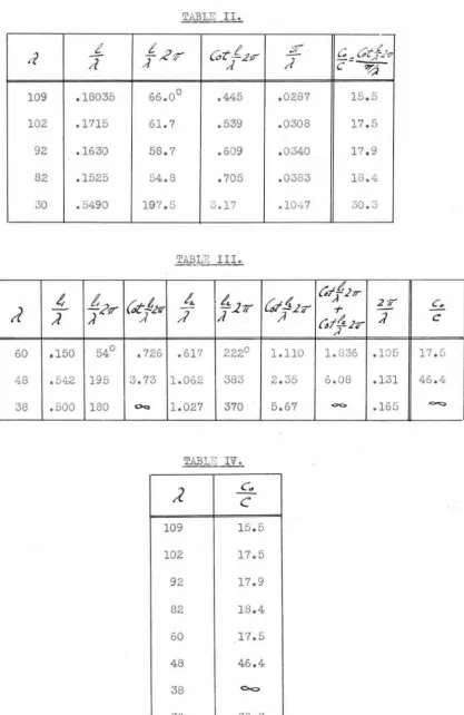
The experimental data is shovm in Table I below.
TABLE I.
rf'c,., 109 102 92 82 60 48 38 30
Ac,,,
40 35 30 25 46 77 58 33.5i';c,,.,
20 17.5 15 12.5 9 26 19 16.75t_ 20 17.5 15 12.5 37 51 39 16.75 •c1n
Calculated values of
..go.
using formula ( 3) for ;J=
109, 102, 92,82 and 30, and formula ( 1) for ,1 =60, 48, 38,cm., are s.D.own in tables
II, III, and IV. The values of
..g.u.
are almost equal for wavelengthsin the region )
=
109 to 60 cm. For shorter wavelengths the vabeof
..2.o
increases. '.i'his increase can not be attributed to inaccuracyc
of measurements but is probably due to the fact that at shorter wave
-lengths some factor other than the cap2.ci tance between t:i1e electrodes
1 lays an imvortant part, as for instance, brn inductance of' the grid
spiral, which has been entirely neglected in the above discussion.
l,Otwi thstandine the fact t!1at the theory- presented above is not
(2
o
)
TABLE II.
·
-_t.
t
((,-t/1121/
.£
c_Ct
f.h
d
/l
/l -~r,,;
C-9fT"
109 .18035 66.0° .445 .0287 15.5
102 .1715 61.7 .539 .0308 17.5
92 .1630 58.7 .609 .0340 17.9
82 .1525 54.8 .705 .0383 18.4
30 .5490 197.5 3.17 .1047 30.3
TABLE III.
ft
t2-.
u~'IT
4
/,.271{,~~hr
c;~d,;1T"
2'//c,.
d
- '17';?
-r
-A
) ) ;/ {#f,{ ,2-q )c
,A
60 .150 54° .726 .617 222° l.llO 1.836 .105 17.5
48 .542 195 3.73 1.062 383 2.35 6.08 .131 46.4
38 .500 180 OQ 1.027 370 5.67 O<:> .165 ~
TABLE
rv
.
;z
-
c
c ..
109 15.5
102 17.5
92 17.9
82 18.4
60 17.5
48 46.4
38 <><::>
[image:26.567.71.488.73.715.2]!.:.%
!:.
.277' ~t~b/-{;t-
t:21Tft%
t+~k'-C.,t-
t!/ 21T ~z .t;+~/I ;J /I ;J ;1 " T~ ;J )
..
T2
,f'(J ..7. 17" - <><> +~
"
() fl.o +~"
(J n . .,.f'p -<'.F/ -1.3/{ 2..376 . .JfS' ~-.J f' -r1.,;y .J'.676
.zu
r:
.>J' f"f":J'J'.J' ti /.88 - .. J2.i" /..?.?.> . b"'Y6 /'1.3 -ri1.3 .2 . .3..?f ·~"7 ~-'YJ ,11.~J
,?~ 15/
"
/ , " d ·7'1.r /.(' . .S .J,7,> ,?_{/(JU,yi;z.
71.1 .12.33..z
(I 12>7 ,.;,;r -f; •7.>·f77 /.J...> .J~r /.q..s . S' .fJ' /.rr 2J',S:r
/~ .ff".Z. -7-26 /.27f" .M6 /ti.~ ~,--;,.,
/0 .b2# /.375
.J . ./If' J.o77
ml,.,. .'n/1-1.
J~.z 2 5,(1(1
.f=-'6t: it, 21T L-/, /,r~
/l /I ,
T%
+~ () () jp . .,
G".?7~ . /s-r Lf'7 'j';.77
.f':.J2r , /J'.>
2.1r
.12.j.r.r: i/11 (1 • /fc; .l.12. ..Z J'. Ii,
f',~7.r ,,; /ti ?.J.> L1.JJ
'T.27Y ·.?.lo .J. rfb /,./. ~~
.l.f 2f/ .26J'
.,,_
z
7
/~.;>l;n/>-?.
12.1"'
/~-Co~
f"""'
1/.37~
/tJ.3,i ~
/(1,(111(1
tf.
t7.r
;?:qy
ff. l.2j/
~f..z3
t7,2ff
,,/ /1 t't
,%
"I+.!{%
;;
"~ c> j""tJ.u
• 17~,J! /, 7"" ~/. 7"
. C?fl /,Pf .J/. r;/
,tJf f /,J'7 2&.57
• /4'2 /. &2 2/..:z.
. ltJJ 17" l~-71.J
, II'/ / .F'2. //, £'2..
. !t/..J 2. 2 ,r 72J'
fn/n,
{. :l Z.
l\:)
(26)
to find hm'l much the natural frequency of the system ehanges if
tiie condenser C0 is displaced from the middle position.
:b'irst, the relation between 11 and 12 will be found for the
case 11
=j:
12 and ):::const. 'I'his can be found from formula (1) ,
p. 23. The results are shmvn in Tables V and VI, and are represented
gra11hically on Diagrarn 7. In general, it can be said, that the sum
1 1
+
12 is ereater when 1 1:f;
l,_ than when 1 1=
l~.In the experiments of this thesis, the value of (1
1
+
1
2) hasbeen kept constant. let us find how much the vrv.veleneth will be changed
if the condenser C0 is displaced from the central position. Formula (1)
can be written as follows:
'
of Cotan_rl11, 2 x
11+ 12 = 210= const. The values
CotanJ 271' and the suJn
Gf~
41k~f;l?f.
are
;ilottedas functions of
J_
) on Diagram 8. If )., is the wavelencth corres1;ondine
.,,,
,l;r-to tlie case 11
-=
12 (or t)t;=O ) , then for a given value of
c
·},,
=~o, wecan find the value of ]" =
13
..
from tl-1e condition that2C
0tf
,.l71 :::-d., •Now, if we make 11 = 10 +.Alo , and 12
=
10 - Al0 , the value of
A
0 will') d .-1 • o( "<
Ao
.
change to /\ an """ vn 11 chan[;e to so that
°'•::::
T
.
'i'he corres)ond1n_9 d.value of ~ wi 11 be:
f
=
~·--;:·curves on Dia.8 the value of
Knowing the value of
r
we can find fro:nf
,
and then tlie valueof
f:
f-f
.
...
e v:ant to ex)ress ,t,t
in terms of the original waveJencthA,.
;
this can be done, ..6~• ~P
..
;\
3.S foilo···s· -
= -
·
-"
•
Ao
A
/\o
APo .J.
=
T
·
"'o
'.i:'hus assur:iing the value of' o<. , ·Ne can fin(:;_ L.e vc...lue of 'vile
TABLE VI.
c
..
,~ Cc~_t..zr t' 2 ?/',.L
c ;J ,,,,7
/!
o.o
.
o
1.57 .250.2 .1 1.475 .234
.4 .2 1.370 .218
.6 .3 1.280 .204
.8 .4 1.190 .189
1.0 .5 1.107 .176 1.2 .6 1.029 .164 1.4 17 .960 .153 1.6 .8 .896 .142
1.8 .9 .838 .133
2.0 1.0 .785 .125 2.5 1.25 .675 .107 3.0 1.50 .587 .0935 3.5 1.75 .518 .0826 4.0 2.00 .462 .0733 4.5 2.25 .419 .0668 5.0 2.50 .380 .0605 6.0 3.0 .320 .0508 7.0 3.5 .277 .0440
TABL:S VII. (30)
<X/ ~=;;/ / 4'/
"/
4~ ,dI,,
Af' <Y /;8~;-
-.::.-·-i::f/
J"
0,F
di
/JD
J
/
«.,
"'
1.05 .953 .1858 .255 .069 6.581.10 .909 .195 .285 .090 8.17 ~ - {'.,.!JI'
.,- c',.J.,.
:Jo1.15 .870 .204 .310 .106 9.22
,/.,
1.177 .850 .208 .333 .121 10.30 /, =)" =/.77
1.25 .800 .221 .380 .159 12.70 1.33 .750 .236 .430 .194 14.50
1.41 .707 .250 .500 .250 17.70
2.11 .95 .132 .171 .059 5.60
2.22 .90 .139 .209 .070 6.30
2.35 .85 .147 .225 .078 6.63 ()/":: 2. () 2.50 .80 .156 .255 .099 7.90
2.86 .70 .178 .313 .131 9.16 13,,=,/25'
3.34 .60 .208 .380 .172 10.30
4.00 .50 .250 .500 .250 12.50
3.16 .95 .098 .126 .028 2.66
3.34 .90 .103 .148 .045 4.05
oio=3.tJ
3.54 .85 .109 .168 .059 5.00
3.75
.so
.116 .187 .071 5.684.28 .70 .133 .233 .100 7.00
;S.='
(}_935.00 .60 .155 .285 .130 7.80
(32}
the curves.on Diugram 9 represent the chu.nt;e of -.vavelen[th
~
\JithI ~
6
e
"
for ti1e condition,\
"
.i."or lart,e
values of
c.
·
211' tne calculated values of the wnvelencths decreaseC. Ao
quite ra_Jidly with the displacement.
~he experimental results, however, s~'low that the wavelent:;th is increasing slightly instead of decreasing when the electrodes are
di s~ilace<i from the central !>Osi ti on. This effect can be ex~>lained
only by the presence of in<luctance as well as ce.1.'aci tm1ce in t110
:-:1icl<lle of tne circuit. This inductance is evidently- the induct~1nce
of the .'.:.,l'id s~iral, :::.nd. its ei':i.'ect will be considered in the next
(d} . =:ffect of lumped inductance in the Lecher system.
If inductances Lo (see l<'ir;.7) are placed in each wire of a
short circuiteci lecher system, the natural frequency of the circuit
~ L,,
I,..
s
.
~
.
1
I / -f-:::f·
-~L.,
c
L,, .. ,L,fzj
.
7
can be found from the followint; conditions:
~
=
1:/·jf
f-a/-7£;
IZC"
w
ez
=
-4..//f
t-a n~
yZC
tu~-e
2
=;·z-..2L.,4.J:r
/-=
-..r ..
c
lu
.I,/ff
CC/nL;ffe"'
..z;
/If
tan
t;
ffe
~
-
Iz.~//F--Cctn
t;
IU-
~
/·z2L,,
tv= -
.z
1
·,!Z:z'Pl',Hr!
ffew -/·12~ c.uill
•
Effect of a circuit of lengt4_ la, having distributed_ capacitance C0and the inductance _10 ;Jer unit length, olaced in the Lecher ~~tern.
~he circuit is re~resented in iig.B.
----
~--- /,,___,_______
~-Fzj.8.
'1.'l1e :t'ollowinc ec;_u.c.ticns cu.n be used to find tlie ns.tura.l frequency
of the circuit:
c;
=-.z;/·/§
/-t:?
/7t:
/IC
U'~=~/·ff
t-c/n/{tLC
U/.. . (7)
.. .
(8)
e2.
=~
L'cis~
/Zj,,
~
+./..Z:
/f!
f//7~
~
?</ . . .(5!}
c;
=eL
us~IZCo
CV+J·.:z;.1~:
J/n
~
IZZ
cu
. . .
/lrj
(34)
or,
::::aiJ:linating I1 and 12 fro:·:1 ( 13) and ( 14) we [et t.D following
relation l;at· :eell :. ,o constants of tne circuit and t!1e frequency:
t~n
~ }7/~n
f,_ ,)-;;-/;-Cs'e',,!L(:.
wl=
L'-C/~
2-tf42."'
+
) ,J
1·
"'J.C.L+Jg
.J,;,
1:12;<:,
UJf;s-t;
q,,
7""' ,/
,?;r+if
er
"f
27
/f
o-
n:
k f 4n
J'".!!7
·
-
:..·v/};N
;/'ZZ,.,
-;fi[
/,;.,
t£
fi.
w
!:-,-t
l'ZG
~
•
. /Tern
f
2r+Z7,_,;
Lw;J.
#
.
.
. .... .
f?)
~o check the correctness of tnis forr'.lulo., •.-,,_ '.ill cor sic:er
several s·,)ecial cases and com11a.re t.:ie results with fornulas derived
·.;.1his is e'd_uivcile1it to for:nula (1) on p.23, where t1"c tot:;;.l ca_1acik..nce
10C0 was denoted bJ C0
.
,-
....
·
11.:Y
( 36)
A co.se of particular interest to us is the following.
Case 3. 11
=
lz
- ,;z;c
ra
?I /.,w.. "'-' ;
j,~/4"$ f., -fhc> )h,;f/z;:t
.z
""Jel"? c~ o, ,
"z
+/Ff
{]fa-,_, / ..#:(i
w; /,
"/?/s ,4 7'je_ /,:/n,'/C,.,4 .2 kljt!-h .L -:? o e>
~---,,,l> ...
(;,f ..,r - LSC'..,Y ,,,_ t':,_sx-/ == -
z.f',,;_.z£ ; -
Zt:1.n%.s-~ .y .<~~~~
z...
.z z
.
. . (2
o)
.
.
t7z
-+
,;T;i:"L!z'a-
#~
d;C
w
. .
. .
.
p
/)
Now, using equation (21) let us calculate the value of
~
C....t..
from the experimental data shown in Table I, p.24, and then
compate it vnth the theoretical value calculated from the
dimensions of the circuit.
To do this, let us rewrite equation (21) in the following
fonn:
where "v" is the velocity of propagation of waves along the
parallel wires (very nearly equal to the velocity of light i f
the da.111ping is small). Denote the value
f
/i:c,27Ttr:::: ....( , t:i1en:;§.
Cran
f
=:t-~n
;Jf 27/ . . . .{22_)
If we l::now "l" and'
!1
"
for twoc,tqn
F
&zp.n
,,J~
then:
from which "x" can be calculated, and then, if the value of "x"
is substituted into ( 22), the value of
/g
can be calculated.However, this method is not accurate, because a small error in
measurements of ''l" or •/l" will result in a considerable error
in "x". We will use another method. We know that for ;/-30 cm.,
1
=
O; hence we can write from equation (22):Cotan .X = 0·
) ' x = l.57 ~= 1.57 x 30 = 47.2
Using this value of "x" the value of
,;:z;-;;-
has been calculatedfC:Z
by means of equation ( 22). The results are shovm in Table VIII, p.38. The average value of
IN
is abouto
.
so
.
Let us now calculate the value of
/g_
from tl1edi~nonsions
c;..L.
(38)
TABLE VIII.
;?
109 102 92 82 60 48 30~ 18.7 16.2 13.7 11.2 6.5 3.0 0
_£2'7T
/1 1.68 .998 .937 .859 .680 .393 0
f'q/7 , / 21'7' 1.868 1.55 1.36 1.16 .809 .414 0
,....
.43 .462 .513 .576 .785 .983 1.57
/l
{"oz'a-.n; 2.17 2.00 1.77 1.54 1.00 .666 0
For two parallel wires, the capacitance and the inductance
per unit iength are found from the followi11£ formulae:
- - - d -·- -.i
Fz5
.
9
.
where p
=
8. 85 x lo-14 and / = 0.4 x l 0 . -8Substituting the above figures and the dimensions of the circuit
in fonnulas (24) and (25), we find:
-/-fl'
C
=
_-h_r_
....
_6'_. B_s-_,.._/_?'_L.-To check:
(o./rj.
The grid to plate capacitance can be calculated approximately
if we assume that the plate and the grid form a cylindrical
I;= J.5"
J
Fzj
.
/(}
.
the ratio 0
§
10condenser of radii rp and rg. ~hen:
-It' /'
L.
=271"? - 27T'-¥8J'5'.</() - ~7(5°..f/il1"7a'r. ··(ib)o
&¢
'l - -t''}f.J.F - · e/>7 ·"' /j .
Since the length of the plate is
eq_ual to 10 -::::: 2.6 cm. , this gives as
the total grid to plate capacitance:
0010
=
115 x l0-14 farads, and(40)
the assumption that the grid inductance is negligible, which is
valid for long wavelengths, gave tne value of C:.t'.,
=
18.There-c
fore we will take C0 equal to:
C0 :=;; 90 x lo- 14 far. /cm.
Hote: Formula (24) gives the value of 00 too small because it
neglects the end effects, which tend ~o increase the capacitance.
To calculate the effective inductance of the grid spiral
accurately is difficult, because it can not be treated as an
ordinary inductance, since the current is dif:t'erent in different
parts of the grid. \lhen the loop of the voltage wave coincides with
the center of the grid, the current is positive in one half of the
grid and negative in the other, thus ehe effective inductance of
the grid spiral is diminished (see Fig.11). I t seems reasonable,
then, to take as the value of the inductance of the grid per unit
length the inductance of one turn times the nunber of turns per cm.
z--r
=
.
05"' Ch?.io=Z.6ch7.
The inductance of a single turn of radius R of wire of radius r,
is expressed by the formula:
cm. •••• ••• ( 27)
Or, since the value of
"!!/
P!-
is small:Substituting the values of R ~ .25 cm. and r
=
.05 cm., we get:The grid has 10 turns yer cm., so the inductance of the grid
per centimeter: 1
=
6 x l0- 8henry /cm. In the above theor..r asymmetrical circuit has been asswjed. Therefore we must talce as the
value of the inductance per unit length of the circuit 10 (Fig.8),
L0
=
1/2 = 3 x 10⁻⁸ henry/cm.Using the values of 1, C, Lo and C0 calculated above, we find:
Considering the roughness of approximations made in deriving this
value, the agreement with the experimental value (0.8) is surprizingly
good. The value of x
=
f"
/L:(',
./-;rzr (see p.37) for the above valuesof L, C, 10 and
c
0 , becomes:x'
=
-y-
2·6 x 21T' x 3 x 10¹⁰ / 3 x l0- 8 x 90 x 10-14 = 40.2The value found on p.37 vvas x = 47.2.
--t' ..Y7. 2
- = - - : : : : and
The ratios:
' 8 0
, G_;7
indicate that the true value of L0 must be:
/./~
s
(
l2
-8I
1
( 42)
The above presented analysis gives the explaination why
the natural frequency of the circuit remained constant when the tube was displaced from the central position: the inductance of
the grid neutralized the effect of the grid to plate capacity.
Analysing the distribution of standing waves on the wires, shown on p.21, it can be concluded that when the frequency approached
J~ 30 cm. the effective length of the grid was equal to half wavelength. For this wavelength, then, the A.C. voltage a~plitude was different for different positions along the grid. The average
value of the voltage amplitude on the grid was less than its maxinrum value, while for longer wavelengths the A.C. voltage was very nearly the maximum throughout the length of the grid. Since the A.C. grid to plate voltage is the factor which produces
oscillations of the space charge which supplies its energy to
the oscillating circuit, the rapid increase of the minimum grid
current when the wavelength approached ~
=-
30 cm., can be under/stood. A short circuited grid as a remedy for this undesirable phenomenon, was mentioned on p. 18.Comparing the circuit shovm in Fig.4, which can be called the "double" circuit, with the circuit shown in Fig.l, it can be said, that the average grid to plate voltage will be higher for
the"double" circuit than for the"single" circuit, which will
result in a greater a."Tlpli tude of oscillations for the sa."!le grid
current for the double circuit. Another advantage in the use of this circuit is the possibility of studying the distribution
of the mechanism of· the generation of Barkhausen oscillations.
It also gives a simple method for the suppression of normal
waves when shorter waves of higher order only are desired.
5. Wavelength measurements.
The first evidence of the presence of oscillations in the circuit is the appearance of the plate current. ~nis current flows in the direction such as to charge the negative plate battery. This
can happen only if the electrons gain more energy in the space
filament-grid than what they loose in their path from grid to plate.
If there were no oscillations the energ~ on the two sides is the sa.'1le and consequently no plate current flows. I f the bridge "B" (F.l)
is moved along the wires while the grid potential is kept constant,
the grid current will be a maximum when the natural frequency of
the circuit corresponds to the electronic frequency or its multiple.
The distance along the wires between the maxima of the plate current
will be then equal to one half wavelength. This is one of the most
convenient methods of measuring the wavelength. If the plate current
is plotted as a function of the position of the bridge, as shown on Diagram 10, and the wavelength is determined from the curve, the
accuracy of this method is quite high ( a few millimeters).
The above described method was used together with another, which
consisted in bringing close to the oscillating circuit an auxiliary Lecher system. Vlhen the natural frequency of the auxiliary system was
the same as that of the first circuit, a decrease of the plate current
was observed, because the auxiliary circuit then absorbed energy from
of the electronic frequency or its multiple, calculated from the
dimensions of the tube. Scheibe's formula (Ref.12) for cylindrical
electrodes "Wa.S used for calculating the wavelength:
In all practical cases the value of rg/rf
>
10 so that the function f(x) is the same for all tubes and is equal to F(x) :::=: .620.For convenience in using the above formula, it can be rewritten
J
=:/
"ou~.
}.,!fff-J+J~/
J~r ~=6
If
(~}//
/
J:/
/=.62o
as follows:
The value of the second term is plotted on Dia.11, p.46, as a function
of the ratio ~/dg • Knowing thms ratio the value of the constant "A"
can be easily detennined from the curve. The use of this method makes
the application of Scheibe's formula practical. The expression:
can be called the "wavelength constant" of the tube, lmowing which the
voltage for normal waves and for higher order waves can be calculated
from a simple formula:
6. Energy measurements.
(a). Plate current.
It was mentioned above that the appearance of the plate current
indicates the presence of oscillations in the circuit. The shape of the curves showing the plate current as a function of the tuning of the circuit resembles the shape of resonance curves (see Dia.10). Let us consider more c&osely in
w't!f
manner the plate current varies with the change in the A.O.potential on the plate which is superimposed on D.C. potential when oscillations are present. In an ideal case, if the qathode represented an equipotential surface, all electrons would move in straight paths radially and approach infinitely close to theplate, then the plate current could be represented by a blocked wave, as shovm in Fig.12. The shaded area would represent half the number
of electrons which passed the grid, and the average value of tho of the current would be
independent of the A.O. voltage. However, in
' '
!_. - - - -_J ; _____ ~ the actual case, the A.O. field acts on electronE
Fzj.
12. throughout the time of their motion from thefilament to the plate; there exists a drop of potential along the filrunent and the electrons have different radial velocities due to deflections from their radial paths caused by the grid spiral. ~11 these factors would tend to make the plate ·current dependent upon the magnitude of the plate potential (A.O.). As a first approximation we would expect that the plate current will be proportional to the voltage
~plitude.
circuit coupled loosely with the Lecher system is found to be
proportional to the plate current. Since the current in such an
a~eriodic circuit is proportional to the A.O. current in the
oscillating circuit, it means then, that the plate current is
proportional to the a.~plitade of oscillations in the circuit.
The curves on Dia.12, p.48, show the plate current Ip, the grid
current Ig and the current in the arieriodic circuit lo<., as
functions of the grid voltage Eg• The current
in the aperiodic circuit has been ~easured by
means of a thermocouJ>le and a e:;al vanometer7 as
shovm in .l!'ig. 13. The curves on Dia .12 siiow
F'z
j
.
13.
that the shages of the _)late current curve andand of the current in the aperiodic circuit are alike. Thus the
measurement of the plate current gives the relative value of the
a..m111itude of oscillations. The grid current (Igl follows the (Io1.l
curve more closely than does the (Ipl curve, but it is difficult
to measure accurately small variations in the grid current caused
by oscillations.
(b) . Thermocouple ~ethod.
As was mentioned above the relative value of the intensity of
oscillations can be measured by a thermocou9le in the aperiodic
circuit. The absolute value of the energJ can not be found by this
method, because the coefficient of coupling between the aperiodic
circuit and the oscillating circuit, and the constant of the
aperiodic circuit is difficult even to estimate, as they depend
but vary also with the frequency. The thermocouple could be
placed directly in the oscillating circuit but this would
introduce a considerable resistance in the system and change
its characteristics, which is undesirable especially because
it is difficult to calculate the constants. Thus the
thermo-couple methods give only the measure of the relative change in
the intensity of oscillations.
(c). Absolute value of energy output.
Some idea of what the absolute value of the energy is, can
be obtained by the following method. It was shown that the plate
current is caused by the A.C. potential on the plate. Onl11 those
electrons will reach the plate which acquired more than zero
energy in passing from the filament to the plate. This energy
has been taken from the A.C. energy. W'nat becomes of this surplus
energy of the electrons which reach the plate? They strike the
plate and their energy is dissipated in the form of heat at the
plate.'Thus the plate current represents loss of energy. This
was first demonstrated by Kroebel (Ref.5). Similar relults have
been obtained by the author. The curves shown on Dia.13, p.50,
were obtained when the plate potential was made negative. Here
we see that while the plate current decreases with increasing
negative plate potential, the current in the aperiodic circuit
increases. This happens because the energy which was lost at the
plate is now delivered to the oscillating circuit. The plate loss
can be measured as follows. The plate current giving the number
of electrons per second which loose their energy at the plate is
known to find the total plate loss. I f we apply a negative potential to the plate, at the sa~e time keeping the A.O.
plate potential the same, the plate current will gradually
decrease. The negative potential at which the plate current
becomes zero will represent the maximum energy of the electrons.
The energy distribution will be represented by a curve shown
on Dia.14, p. 52; by integrating this curve the total energy
loss at the plate (WP} can be found.
The plate loss is not the only loss. Some power is expended
due to resistance and radiation of the circuit. The theoretical
considerations of the mechanism of oscillations of the Barkhausen
tube lead one to believe that there exists an energy loss at
the grid. By the grid loss here is meant not the loss Ig Eg, but
a loss similar to the plate loss due to the oscillations. For
practical purposes the radiation loss may be considered the only useful energy, so that it is desirable to eliminate all other
losses as completely as possible. T'De ohmic resistance of the circuit is usually very small. The grid loss can be decreased b~r
making the grid of thin wires, althogh the grid loss can not be
eliminated completely. The plate loss is decreased by a9plying
negative potential to the plate. The curves on Dia.13 show the increase of the intensity of oscillations when the plate loss
is decreased. The maximum of intensity is reached when the plate
current is reduced to zero. With further increase in voltage the
intensity of oscillations decreases because the oscillating space
charge is farther away from the plate and the voltage induced by
it on the plate is smaller. The ratio I,;./I._ represents the increase
(54)
in the amplitude of oscillations which can be obtained with
optimum value of' the plate voltage. I f the plate loss is
measured for zero plate voltage, the maximum energy output
of the tube can be approximately calculated from the formula:
VI (Ic<
)z
p \Io\o
7. Dependence of energy output upon the emission current.
a) Limits of maximum energy output.
The above derived relations are applicable to cases when the
tube is operated with constant emission current. The increase in
emission current increases the intensity of oscillations. The curves
on Diagram 15 and Dia.16 are typical curves representing the change
of the intensity of oscillations with the emission. T'ney show that
the oscillations begin only at a certain minimum grid current. The
intensity increases very rapidly at first and then reaches saturation.
This effect is quite important since it shows that the energy output
of the Barkhausen oscillator can not be increased indef;ini tely by
increasing the emission. The voltage at which the saturation is reached
is approximately the voltage corresponding to the saturation current
on the static characteristic. This then, represents the upper limit
of energy which can be obtained with a given tube. This saturation
effect can be explained by the screening action of electrons which do
not deliver energy to the circuit but form a dense space chargg around
the electrodes, tnus disturbing the oscillations.
One interesting feature of these curves (Dia.15) is that the
important point is that the optimum negative plate voltage is not directly proportional to the amplitude of oscillations, but seems to be also a function of the grid voltage and the emission current.
(b). Ex.)erience with water cooled grids.
Results similar to those shown on Dia.15, were obtained for tubes with water cooled grids. Figures 14 and 15 show the general view of the construction of the tubes. The saturation was also reached at voltages corres~onding to the static saturation curves. In most cases, however, the minimum grid current \V8.S considerably
higher than for radiation cooled grids, which can be explained by the coarseness of the grid which had to be made of tubing of larger diameter than the dia~eter of wire used for radiation cooled grids. The maximum intensity of oscillations that could be obtained with these tubes was usually smaller than for ordinary tubes. Thus, in general, it can be said, that the use of water cooled grids is not a solution for increasing the energy output of the Barkhausen oscillator, since other factors, such as symmetry, proper design of electrodes and sharp tuning of the circuit, are of a greater importance than the excessive heating of the grid.
(c). Minimum wavelength as a function of tube constants.
The above tests demonstrated the existance of the lower (Ignin) and the upper (Igmaxl limits of the grid current (the latter
corresponding to the maximum of energy output). Obviously, the tube will produce oscillations only if Igmax)>Igmmn. The dependence of
rgnax
upon the voltage can be approximately expressed as follows:where the constant "k " can be called the saturation constant s
of the tube. I t depends in a known manner upon the dimensions
of the electrodes and can be calculated. In the short wave
region the value of Igmin can be expressed as (see p.20):
·where
"ks"
can be called the excitation constant of the tube.The condition for oscillations requires that:
Ignin
<
rgnax,
or:Expressing the voltage Eg in terms of the wavelength and the
wavelength constant (see p.45), we get:
A similar expression for waves of order "n" will be:
=
Keh
%..
~
~L .
L-
;!;~
;
-
.
cJ+o//z;
_,'-fmm ~?"
,
~"714,r~-
ffer. /.
~K.3
(J-r1-n_J3
.
-~
h1/h. ;J
These relations show that shorter wavelengths can be obtained
for higher order waves. However, the excitation coefficient for
high orders "k 11 depends a great deal upon the symmetry, so that
en
higher order waves are obtained only when the tube is symmetrical.
The value of the excitation coefficient depends not only u;ion the
design of the tube, but also upon the nature of the oscillating
(60)
8. Conditions for maximum energ;y output.
The conditionsfor obtaining maximum energ;.J output from the Barkhausen oscillator will be here summarized:
a) The oscillating circuit must be tuned to the most probable electronic frequency or its multiple (Ref. 1,3,4).
b) The emission current must be high, aL111ost reaching its saturation value.
c) The plate voltage must be :negative and adjusted for maximu.111 am_;_1li tude so as to eliminate the plate loss (Ref. 5).
d) 1r11e tube must be symmetrical in order that higher order wt;.ves
could be obtained (Ref.7).
e) The A.C. volt[lge betv1een the electrodes must be a maximum, which can be obtained by placing the electrodes in the loop
of the voltage wave, as has been described in paragraph 3 of this paper.
The above are the most essential requirements. Other factors,
such as the construction of the grid, the ratio of the diameters
of the plate and grid, their size (diameter and lencth), the size
and the material of t:ie fila.'Tient, the degree of vacuu.111 in the tube,
and many other factors i1ave effect U)On the operation of t!~e tube.
But a systematic study of their effects has been very d.ifficult,
since they were usually masked by the more ir12ortant ones. It is
In conclusion, the author wishes to ex.!.Jress his ap1)reciation for the assistance rendered by :t:r. William Clancy in the construction of the tubes, the advice and suggestion:;; by Dr. s.s.Mackeovm, and the interest in this work shown by Professor R.'J.Sorensen and Dr. R.A.11illi1rnn.
Kelloee Radiation Labor~tory,
(62)
References:
1. H.Bar:imausen and h.irnrz, ?hys.ZS, 21, 1, 1920.
2.
:-r
.
E
•
.Hollmann, ZS i'Ur Hochfrequenztechnik, 33, 1929, :JP• 27, 66, 101. 3. G.?otapen1co, ZS f.T.Phys., 1929, p.542.4. G.Potaperuco, Phys.Rev., Vol.39, 4, 1932, p.625, 638.
5. ".'.Kroebel, ZS f. Phys. ,61, 3,4.
6. :C.Gill and J.Morrell, Phil.liag., 44, 161, 1922.
7 • .1:H 1.!ainberg, Journal of Applied Physics, Vol.VII, I, 1930. (Russ.).
8. Ii.Kapzov, ZS f. Phys., 129, 1925.
9. F.Ollendorff, Die Grundlagen der Hochfrequenztechnik, Berlin, 1926.
10. H.G.~-~ller, Slektrische Nachrichtentechnik, April 5, 1930.
11. H.:..::.IIoll.>nann, .Ann. cl. ?hys., 86, 1928, p.1062.
12. """.;:;cheibe, .~nn.d • ..-hys., 73, 54, 1925.